Empennage- Tailcone
|
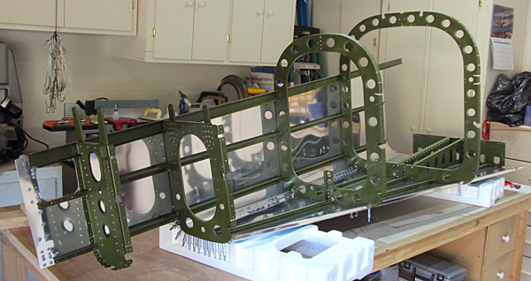
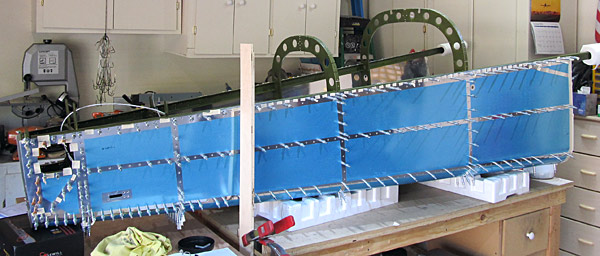
I ordered the Empennage/Tailcone Kit to build first in the RV14A project. Van's Aircraft does not provide a "QuickBuild" option for the empennage.
|
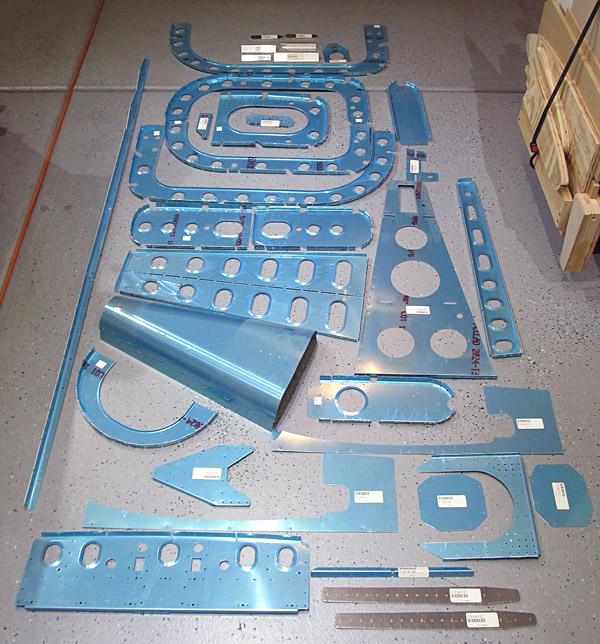
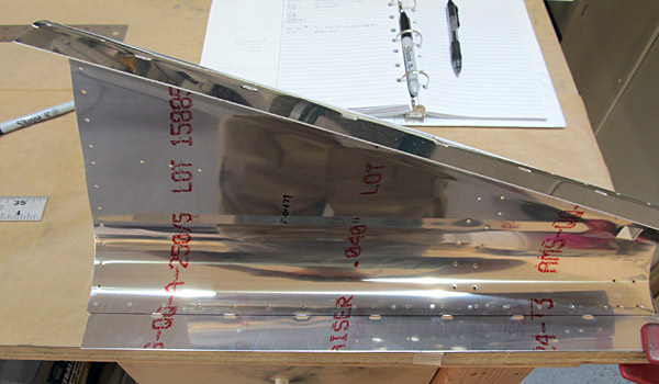
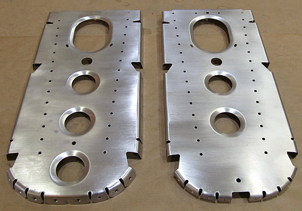
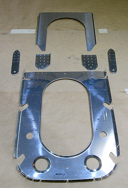
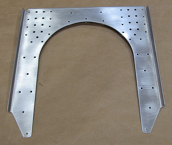
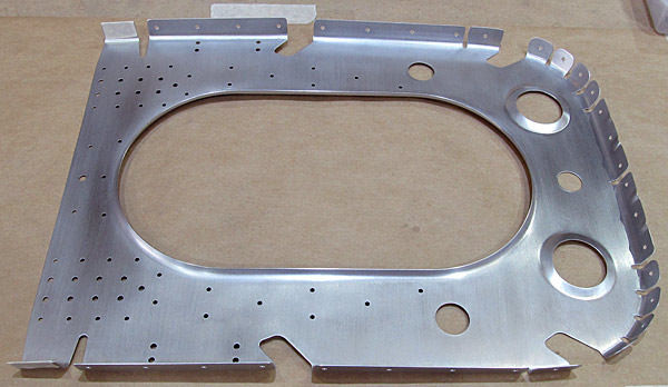
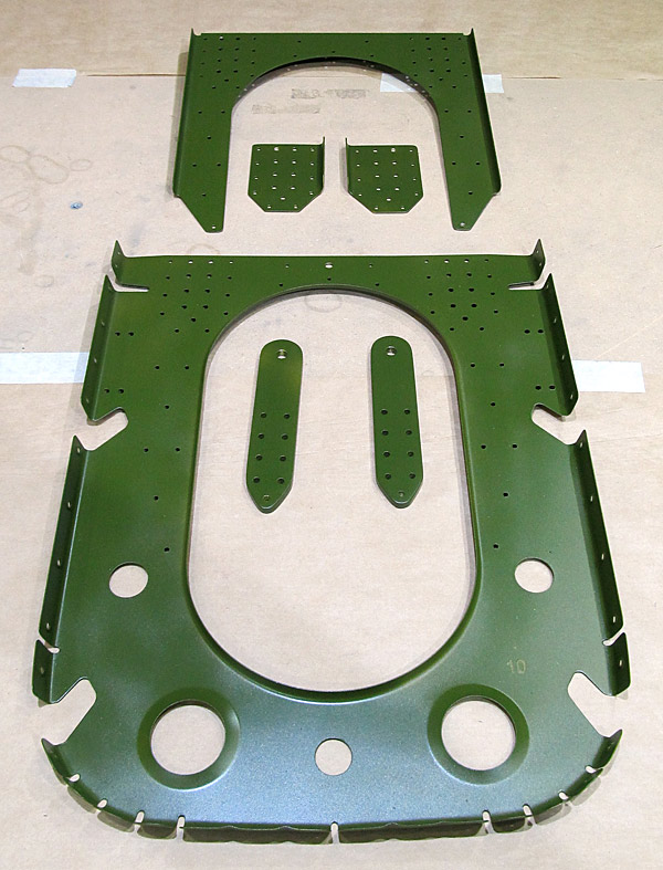
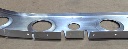
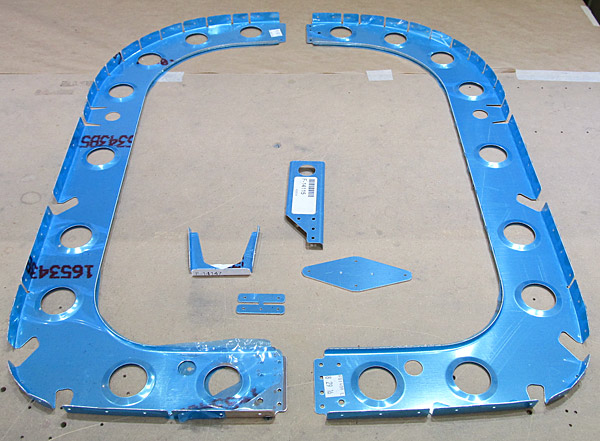
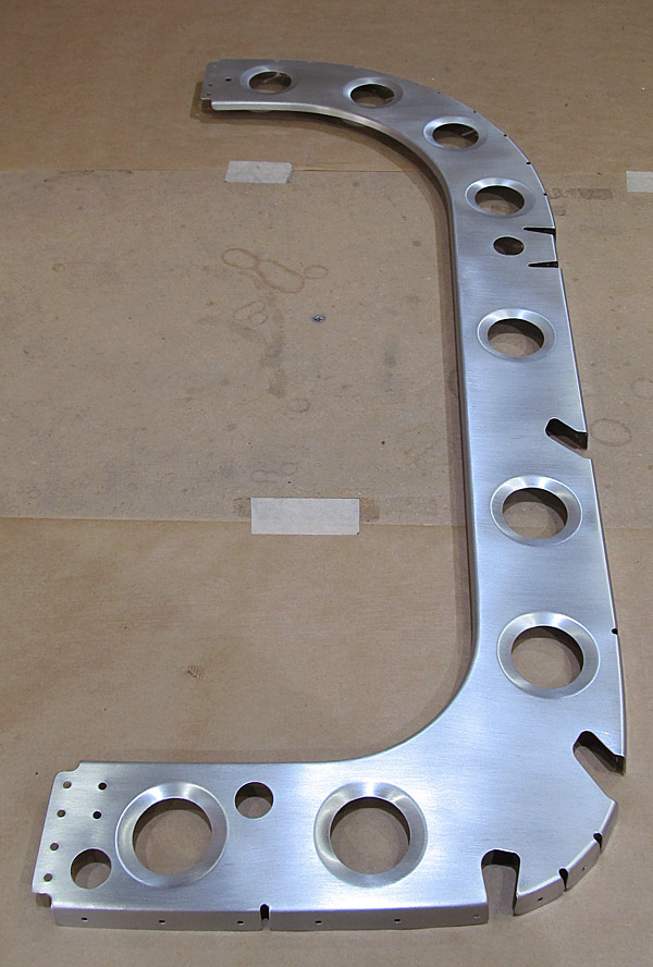
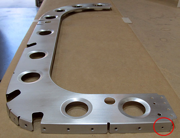
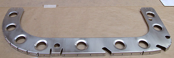
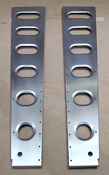
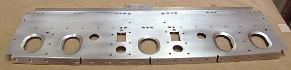
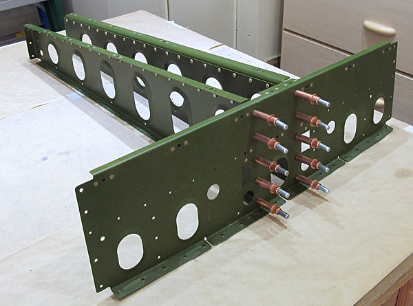
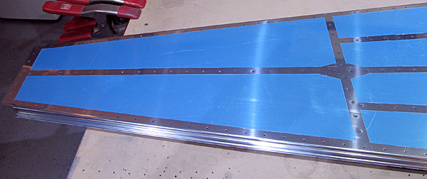
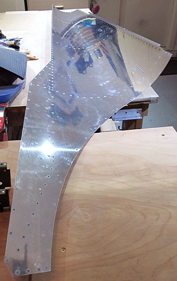
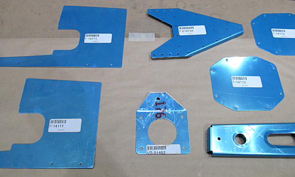
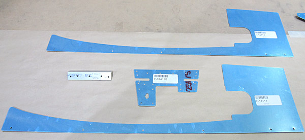
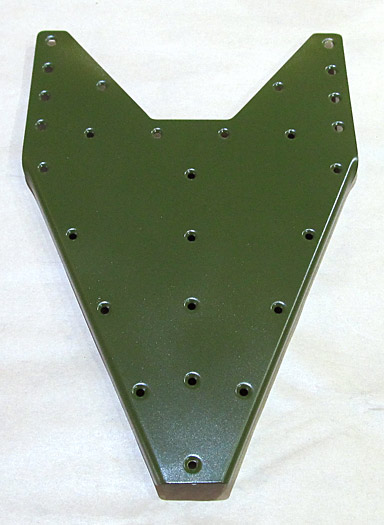
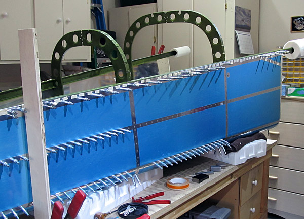
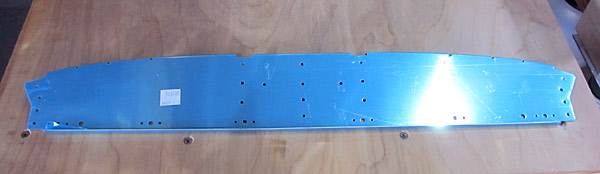
These are all of the parts except for the longerons, bottom skin, side skins, wiring, and cables. |
 Basically, the empennage kit includes everything aft of the canopy and is about half of the total fuselage.
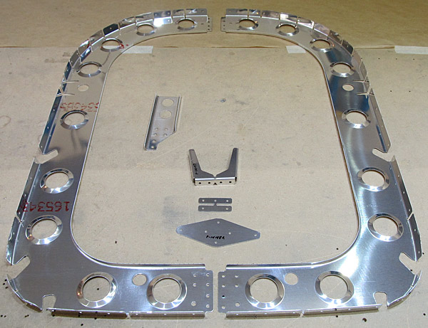
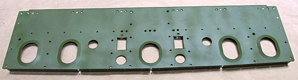
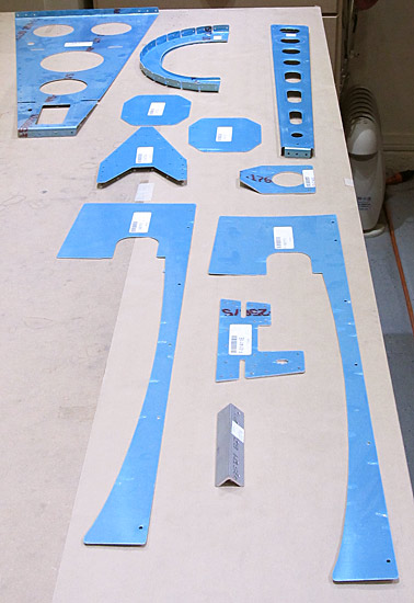
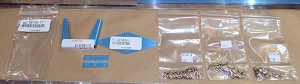 These are the parts that are needed to comply with Service Bulletin SB 18-09-17 that deals with skin cracks that may develop in the bottom skin. |
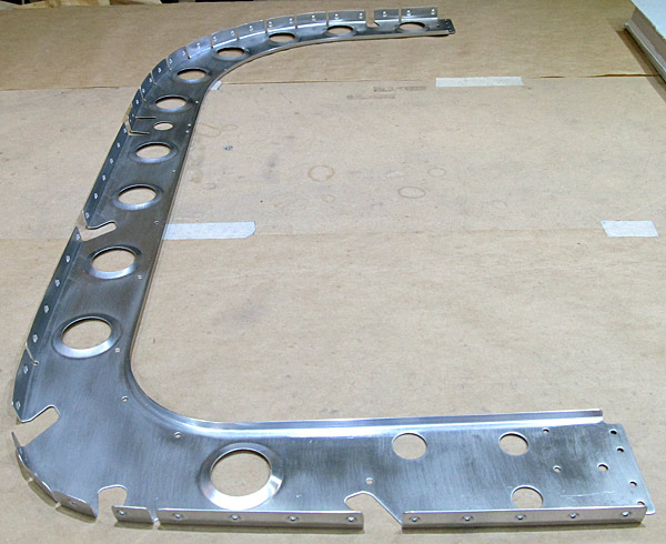
 The first couple of pages in the tailcone section of the builder's manual instructs you to modify and separate parts from one another. |
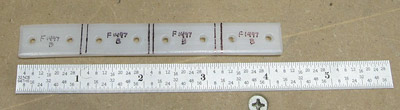
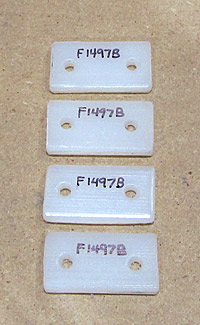 Four (F-01497B) Cable Guides! |
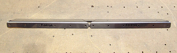 The stiffner angles (F-01473A) are next to be separated. |
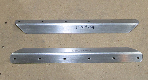 The stiffner angles (F-01497B) were then deburred and I scuffed them with ultrafine Scotchbrite pads because they will be primed later. |
 Next items to be separated are the aft fuselage "J" stiffeners (F-01486D, F-01486E, and F-01486F). |
 Tin snips does the job! |
 Of course once the parts are cut you have to debur them. |
 I like to scuff the parts with ultrafine Scotchbrite pads because they will be primed later and it it easier to do that now before they get dimpled later on. |
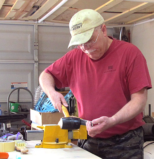
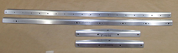
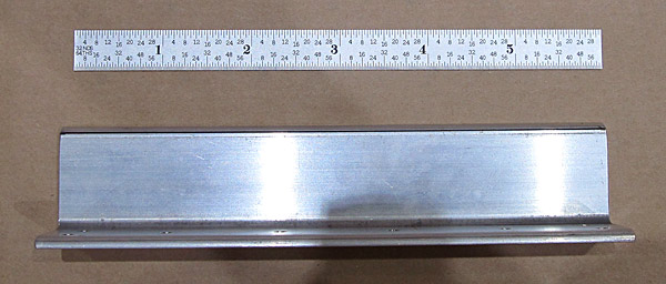
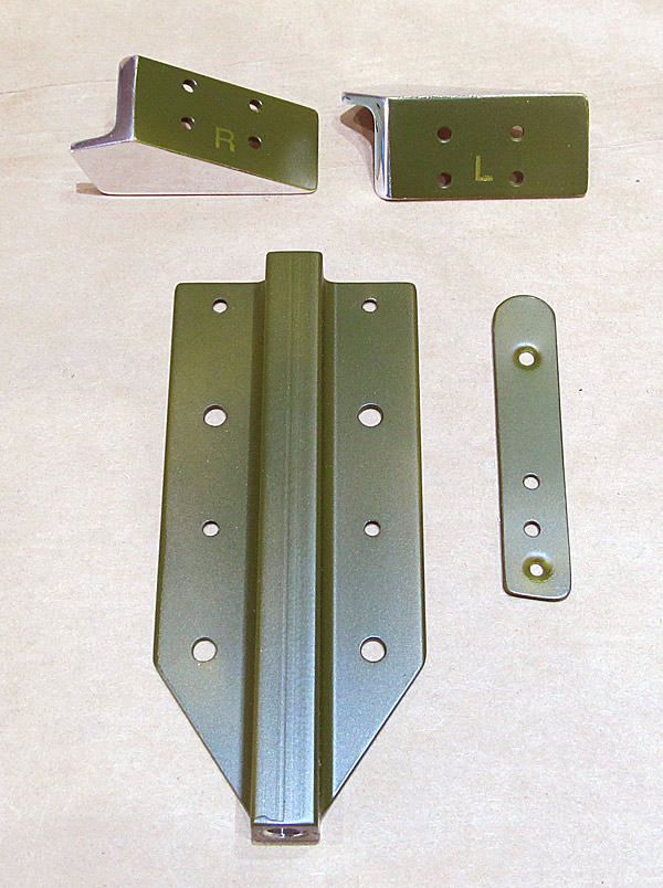
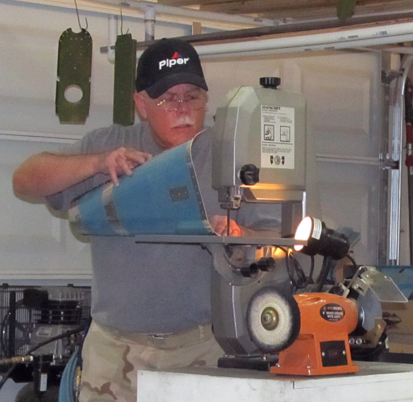
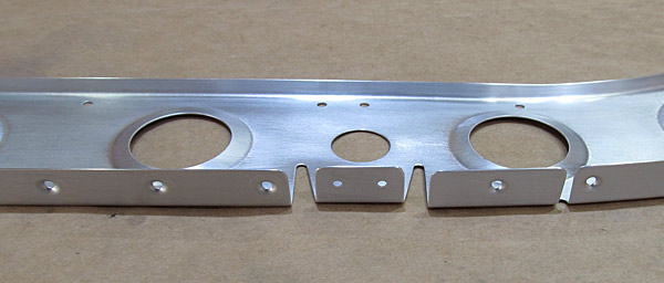
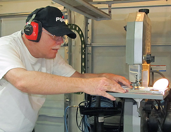
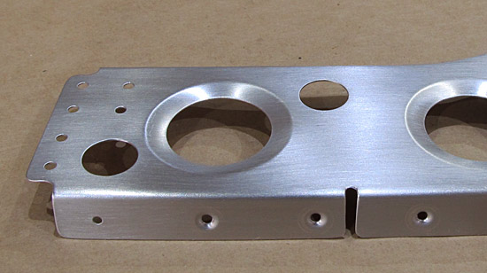
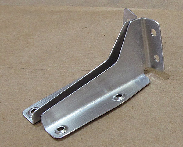
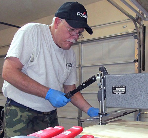
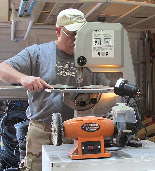 The battery angle pieces (F-1037B, F-1037C, and two F-1037A's) get separated next and the metal is thick enough that I had to use the bandsaw to do the cutting. |
 Battery angle (F-1037B) needs to basically have a notch cut into it but in order to do so there is a specific way to perform the task. |
|
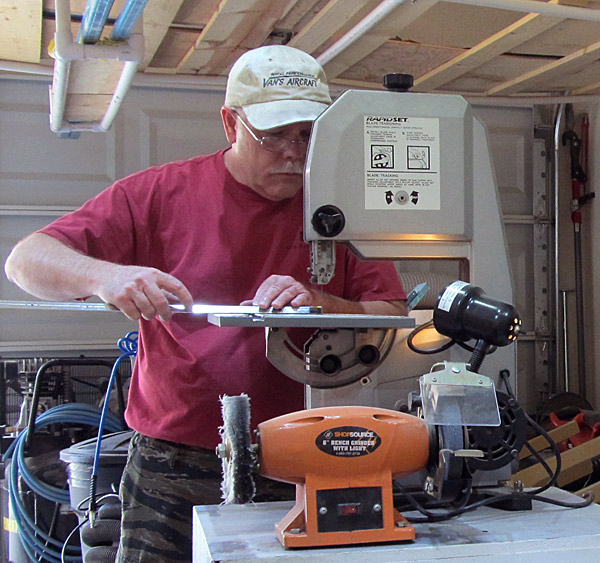 After the drilling operation, the notch was cut out on the bandsaw. |
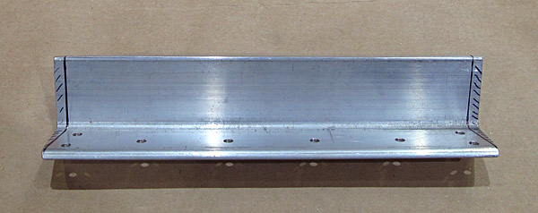
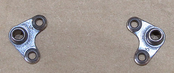
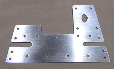
 This is the finished (F-1037B) battery angle after deburring and scuffed with ultrafine Scotchbrite. |
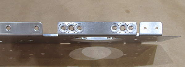
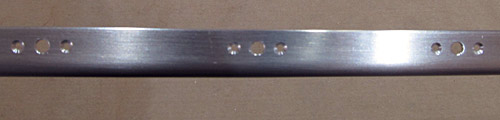
 I jumped ahead a few steps to straighten out the bow in the horizontal stabilizer attachment bars (F-01411C's). |
 Back to the deburring of the battery angle pieces..... |
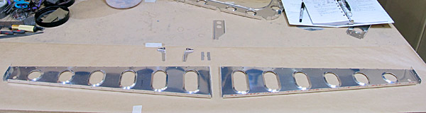
 The bulkhead doublers (F-01410B-L and F-01410B-R) were labeled, and separated next and then deburred and scuffed in preparation for priming. |
|
|
The horizontal stabilizer attachment bars (F-01411C's) were deburred and scuffed in preparation for priming. |
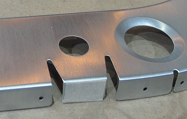
 There are four "J" stiffeners that need to be modified. |
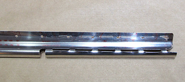 The material that needs to be removed is the metal that is below the slots that you see in this photogragh. |
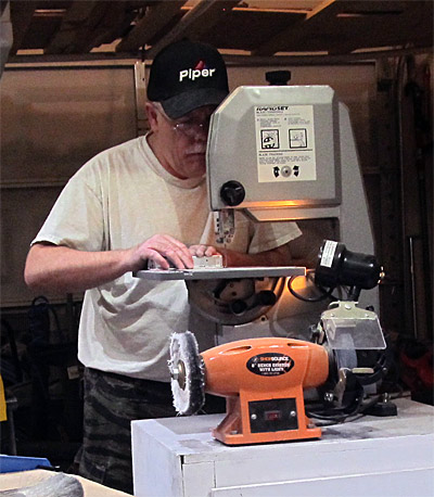
 The metal is thick enough that it is easier to remove it with the bandsaw so that is what I did. |
 While I had the bandsaw out, I cut off the excess material (the small tab) that is required to be removed from the aft fuselage longerons (F-01418B-L and F-01418B-R) as described in step 2 on page 10-03 in the builder's manual. |
 Of course after cutting or drilling anything the piece needs to be deburred. |
 Here is one of the "J" stiffeners (F-01486A-R) after it has been deburred and scuffed with the Scotchbrite pad. |
 The aft fuselage "J" stiffeners (F-01486A-L, F-01486A-R, F-01486B-L, and F-01486B-R) have been edge deburred and scuffed with ultrafine Scotchbrite pads in preparation for priming. |
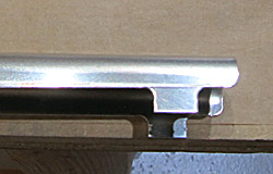
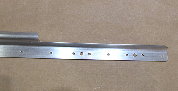
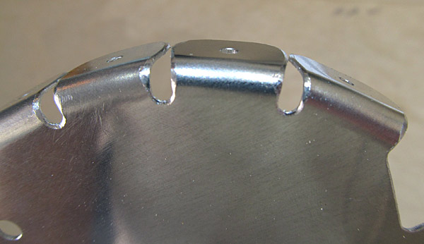
 Here is what the ends of the "J" stiffners look like, two of the ends are ones where the excess material has been removed. |
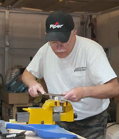
 Now it's time to remove the excess material on the longerons (F-01418B-L and F-01418B-R). |
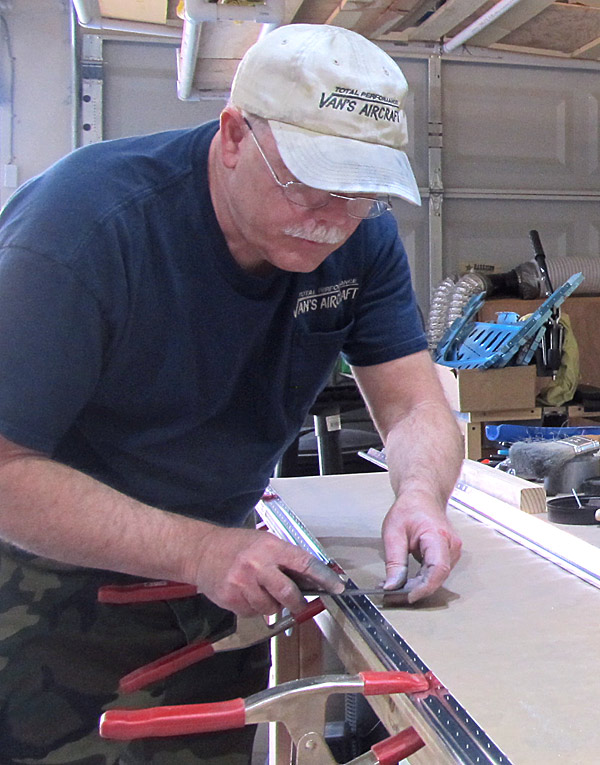
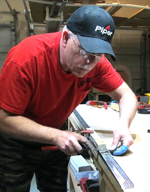 After filing down the "tabs" to the reference lines....you guessed it, the edge deburring begins! |
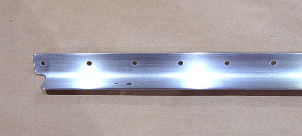
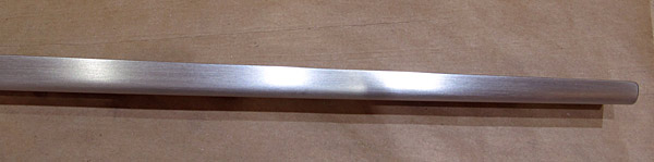 Here is what the longeron end that had the "excess tabs" removed looks like after the debur process. |
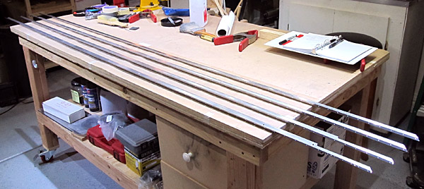
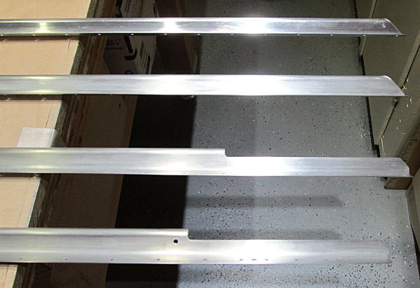
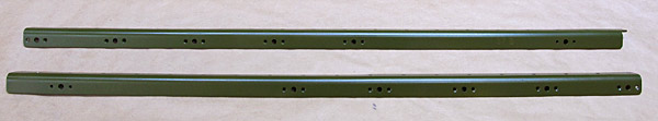
 Here are the longerons (F-01418B-L and F-01418B-R) after they have been edge deburred and scuffed with ultrafine Scotchbrite. |
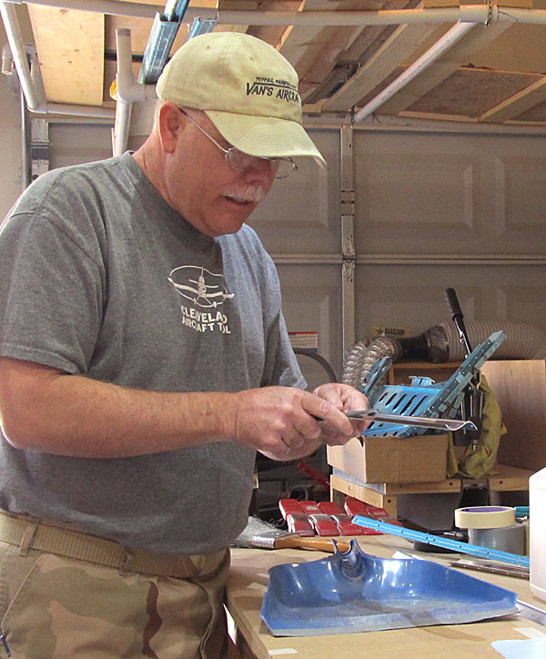
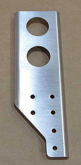
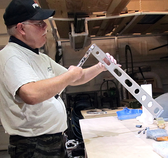
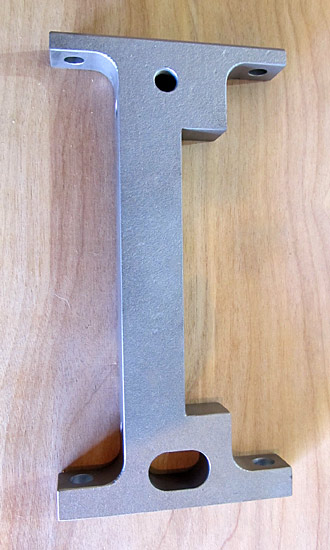
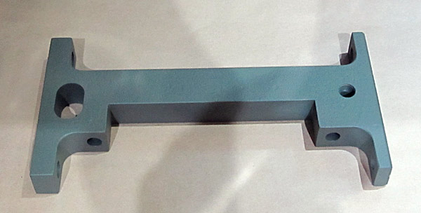
 The fabrication of the horizontal stabilizer attach bar support angle (F-01411D) is next. |
 I started out by trueing up the side of the aluminum angle that doesn't have any pre-drilled holes in it because it does need to be shortened slightly. (It is 1 5/32" tall.) |
 Next, the sides of the angle have some excess material to be removed. |
 Of course the material is thick so I elected to make the cut using the bandsaw. |
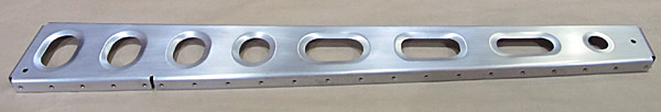
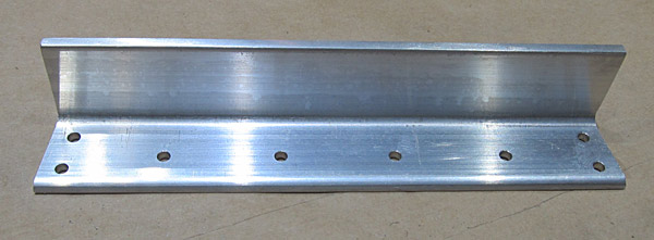 Here is what the angle looks like after the cut has been made. |
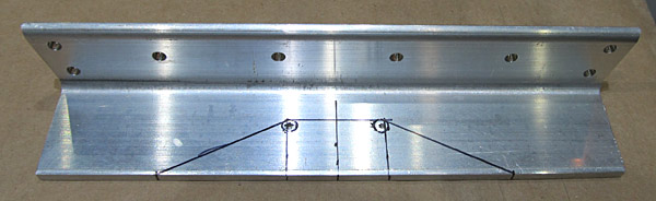 Next I laid out the lines to cut out the material in the middle of the horizontal stabilizer attach bar support angle (F-01411D). |
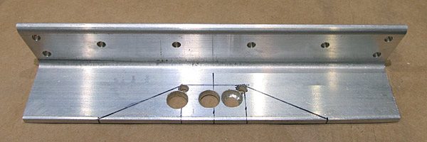 I drilled holes at each corner of the 1" gap so that the cuts would have a radius...don't need any stress risers here! |
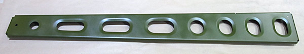
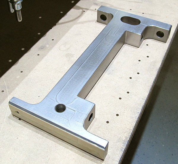
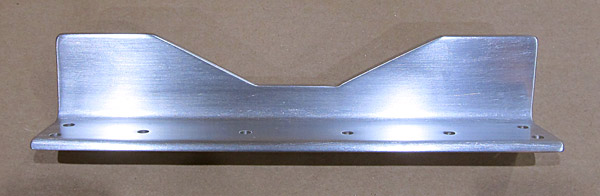 Here is the finished (for now) horizontal stabilizer attach bar support angle (F-01411D). |
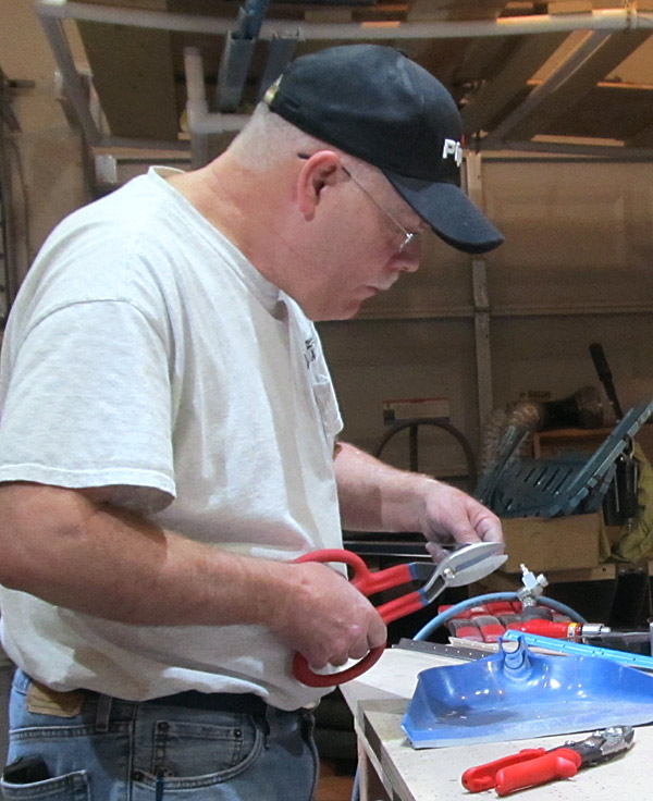
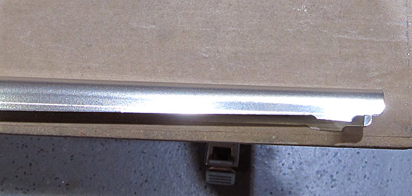
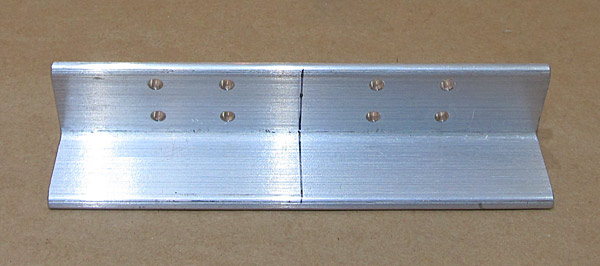 Fabrication of the rudder stops (F-14113-L and F-14113-R).is next. |
 The aluminum angle is then cut into two equal halves using the bandsaw. |
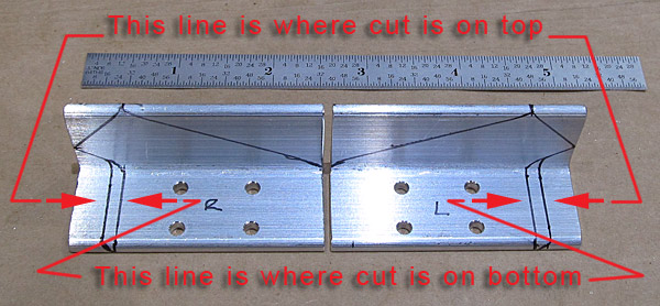 I laid out the reference lines according to the directions in the builder's manual on page 10-04. |
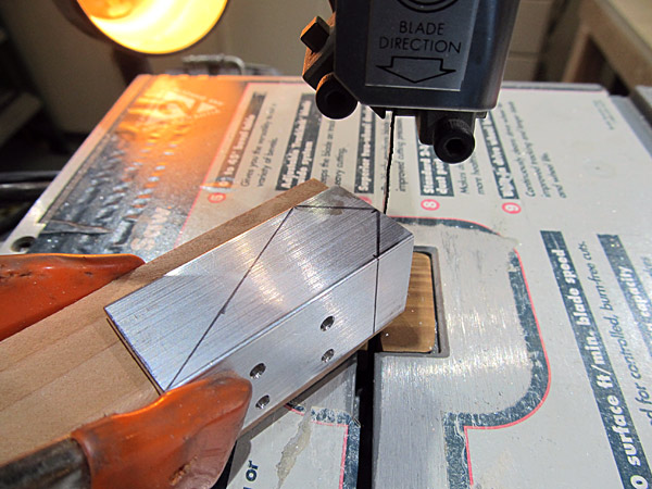 I used a piece of scrap wood to support the aluminum angle as I cut it on an angle and I also cut just "wide" of the lines so that I could later file down to the reference lines and make an accurate rudder stop. |
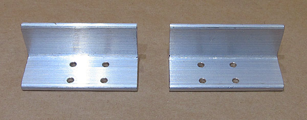
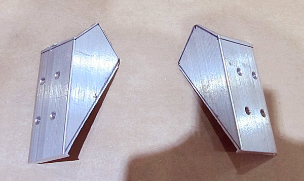 Here are the two roughed out rudders stops (F-14113-L and F-14113-R). |
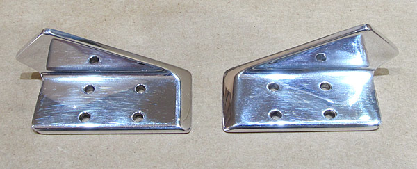 I wanted our rudder stops to have some "bling" so I went ahead and polished them too! |
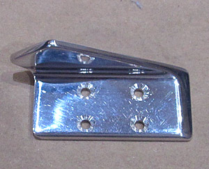 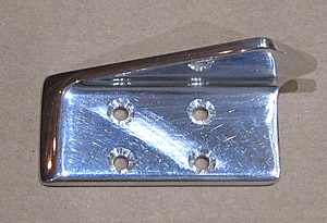 The #30 holes were machine countersunk so that they can recieve AN426AD4 rivet heads. |
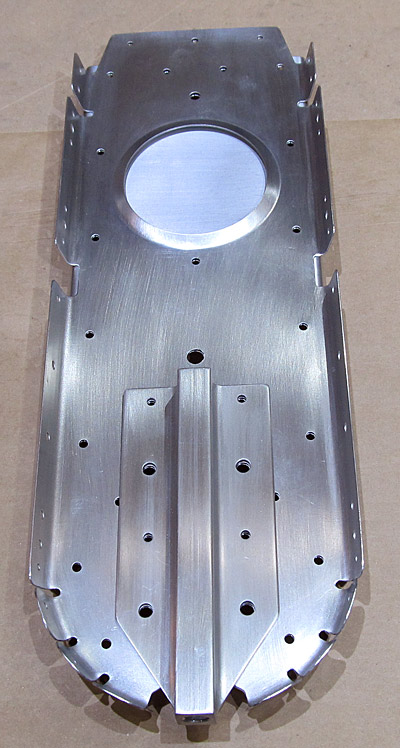
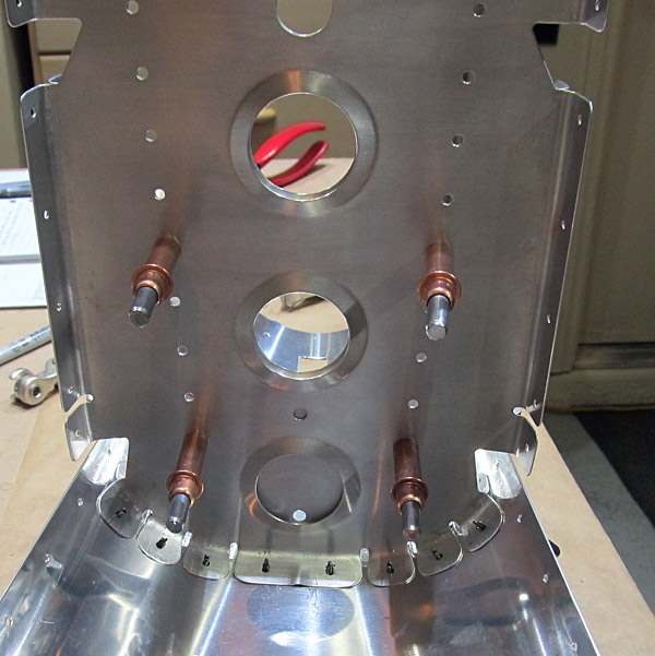
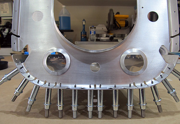
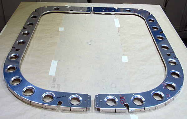
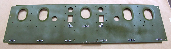
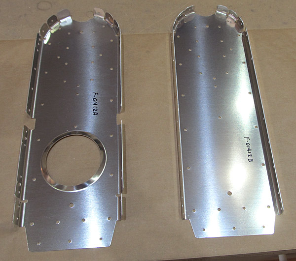 The aft fuselage bulkheads are next to be worked on. These are the very aft-most bulkheads and there are two of them (F-01412A and F-01412B). |
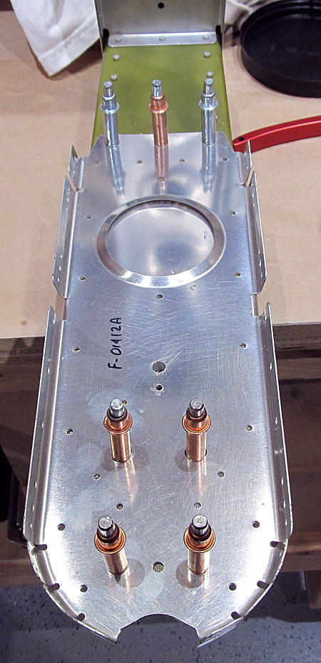
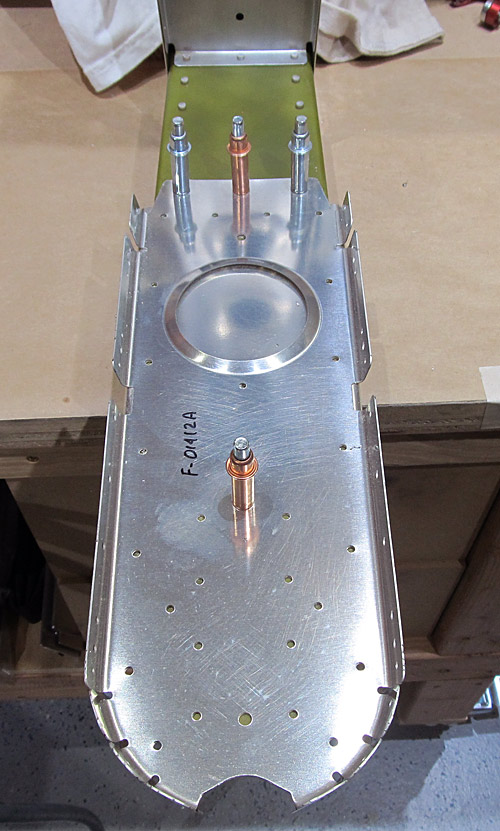 The two bulkheads, (F-01412A and F-01412B) are clecoed to the vertical stabilizer using two vertically aligned #30 locator holes. |
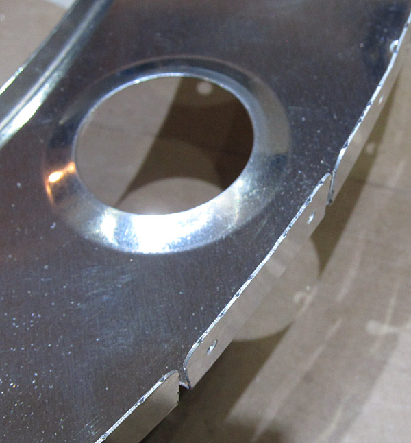
 (*You can see the systems hole in this photograph, it was just enlarged to 17/64".) |
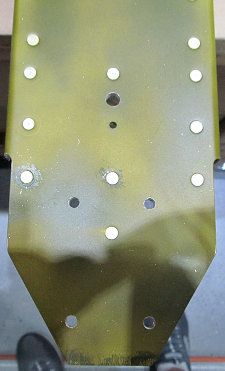 Here is what the match drilled holes look like in the vertical stabilizer. |
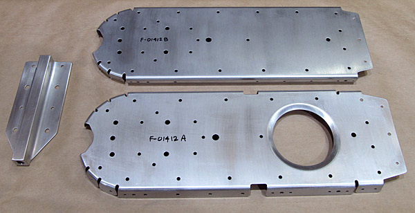
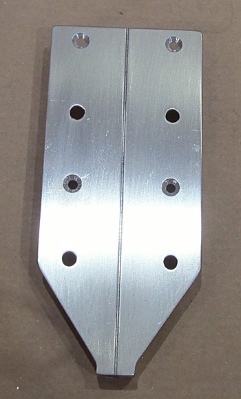
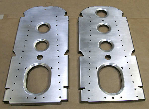
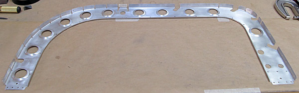
 These are the two bulkheads (F-01412A and F-01412B) and the tie down bracket (F-01412D) after drilling the #12, #30, and #40 holes. |
 The two bulkheads (F-01412A and F-01412B) and (F-01412D) were deburred and scuffed with ultrafine Scotchbrite pads in preparation for priming before the next step which will call for dimpling and countersinking because it is easier to do it in this order than after the dimpling process which "eats up" the Scotchbrite pad |
 Not all of the holes in the web receive dimples so we marked them with masking tape so as not to accidentally dimple them. |
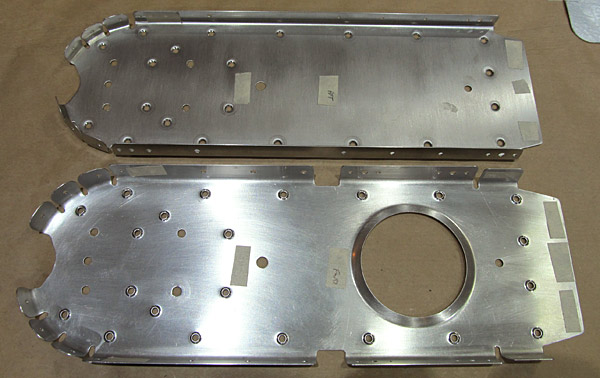
 Here we dimpled the #40 indicated holes on the flanges of the bulkheads. |
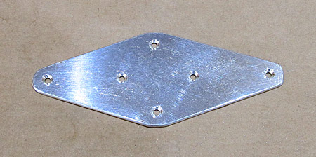
 The four #30 holes in the tie down bracket (F-01412D) were machine countersunk with the manufactured heads of the rivets to be located on the aft side of the bracket. |
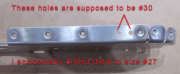 I hate to admit it but I opened up two #30 holes to a #27 size when they should have remained a #30 size. |
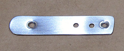 This is the doubler that I made. |
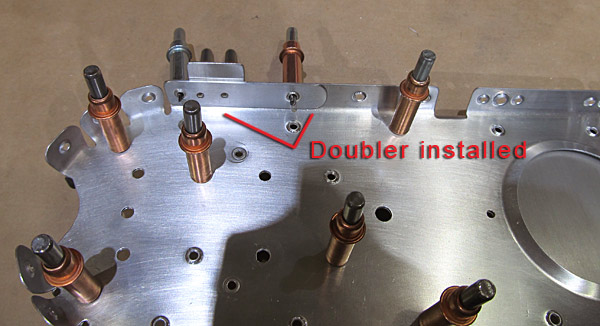 Here is the flange doubler installed. |
 The #27 holes where the nutplate will be for the inspection panel were dimpled using a #6 screw dimple die. |
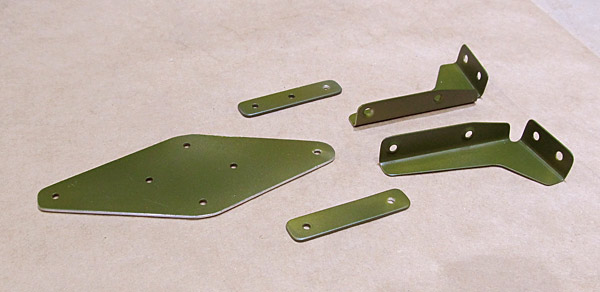
 The tiedown bracket (F-01412D), rudder stops (F-14113L and F-14113R), and doubler were washed with acetone and primed with Tempo A702 green zinc phosphate primer. |
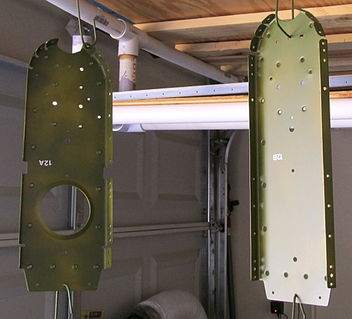 The aft fuselage bulkheads (F-01412A and F-01412B), were washed with acetone and primed with Tempo A702 green zinc phosphate primer. |
 Now on to the next row of bulkheads (F-01411A and F-01411B).... |
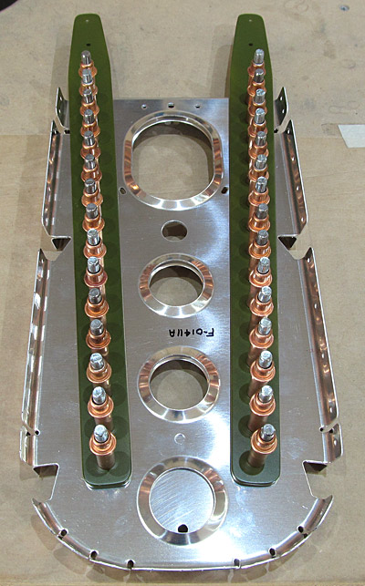 The horizontal stabilizer attach bars (F-01411C) and the bulkheads (F-01411A and F-01411B) were clecoed together to check for proper alignment and fit then the bars were labeled, to ensure proper placement when they would be later reassembled for final riveting, and then everything was disassembled. |
 *Be sure to facet the flanges so that the skins aren't scratched when they are installed...it's a tight fit. |
 I like to smooth the edges with 600 grit sandpaper and scotchbrite pads. |
 Here are the bulkheads (F-01411A and F-01411B) after they have been deburred and scotchbrited in preparation for priming. |
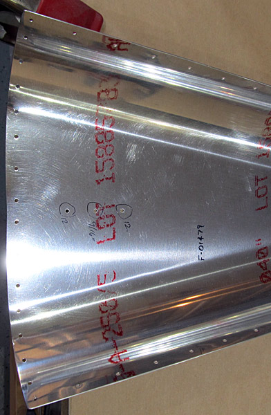
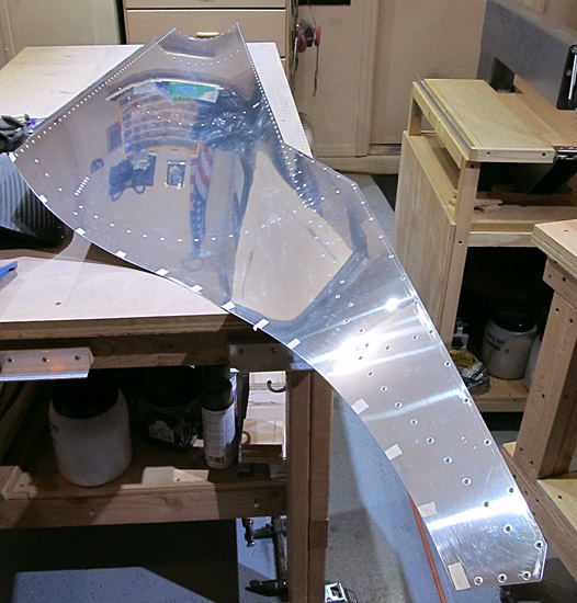
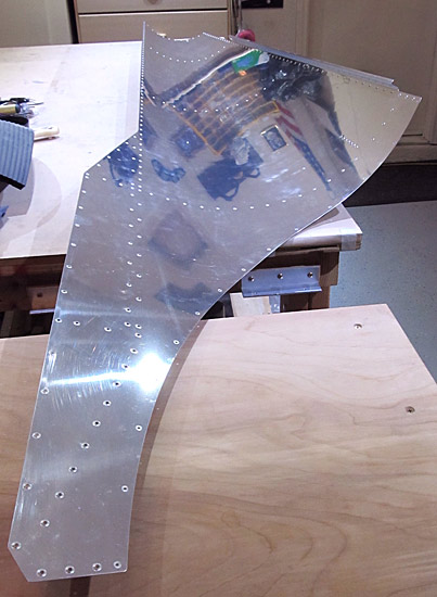
 The next step is to flute the bottoms of the bulkheads (F-01411A and F-01411B) so that they will fit in the aft bottom skin (F-01479) but before I did that I went ahead and trimmed the excess material as directed on page 10-15 of the builder's plans. |
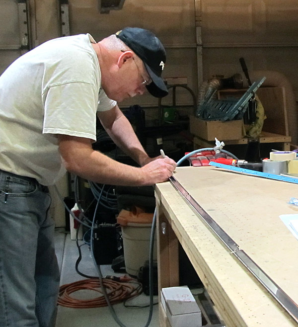
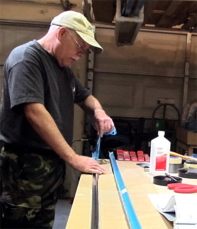
 I started out by drawing a double set of reference lines along the skin so that when I was cutting on the bandsaw I could easily see and guide the blade during the cut. |
 See what I mean! |
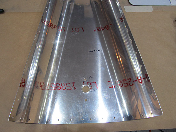
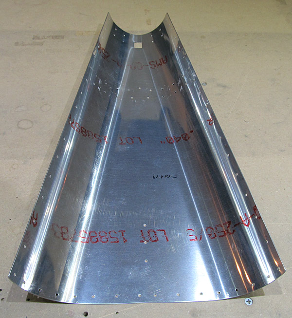 I final reamed and deburred all of the #40 holes in the aft bottom skin (F-01479) and deburred the edges of the skin as well. |
 Now I am ready to flute the bulkhead (F-01411A and F-01411B) flanges! |
 It took a little while and I had to assemble and disassemble everything a few times but I think I got the flanges fluted pretty well. |
 Dimpling the bulkhead (F-01411A and F-01411B) flanges is next. |
 I primed the bulkheads (F-01411A and F-01411B) with Tempo A702 green zinc phosphate primer. |
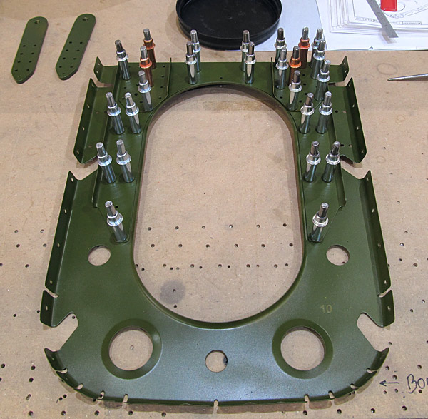
 It is time to rivet the bulkheads (F-01412A and F-01412B) and the tie down bracket (F-01412D) together. |
|
|
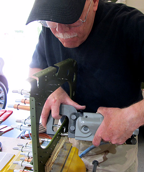
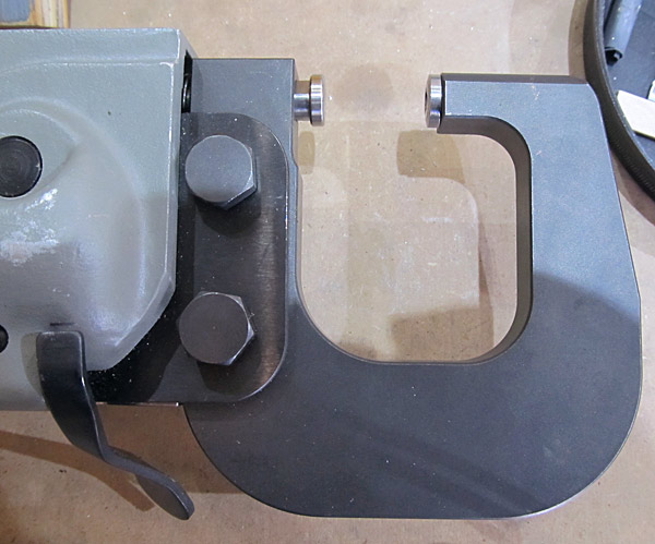
I used our pneumatic squeezer with a longeron yoke installed to set the rivets. |
|
|
We set the four AN426AD4-5 rivets to attach the tie down bracket (F-01412D) next. |
 The manufactured heads of the rivets are on the aft side of the assembly. |
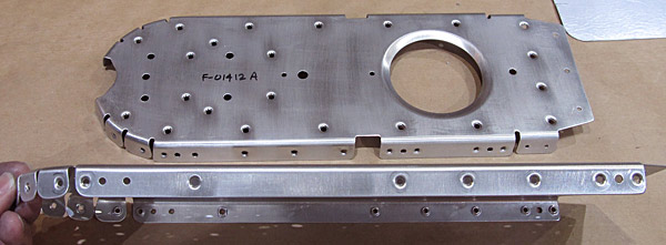
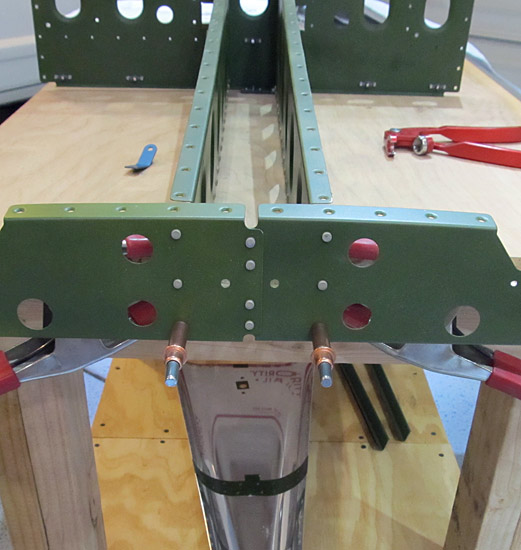
 The bulkheads (F-01412A and F-01412B) and the two horizontal stabilizer attach bars (F-01411C) were clecoed together in preparation for riveting. |
|
 Time to work on the next bulkhead assembly. |
|
|
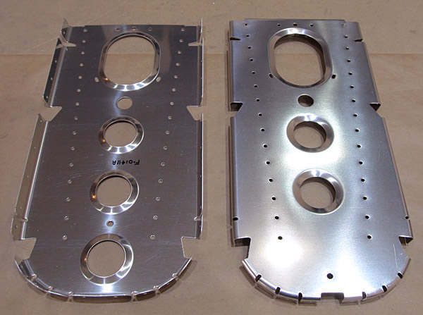
We started out by final reaming all of the #40 holes in the flanges and the #30 holes in the web of bulkhead (F-01410A). |
|
|
We final reamed all of the #40 holes in the flanges and #30 holes in the web of the bulkhead doubler (F-01410A). |
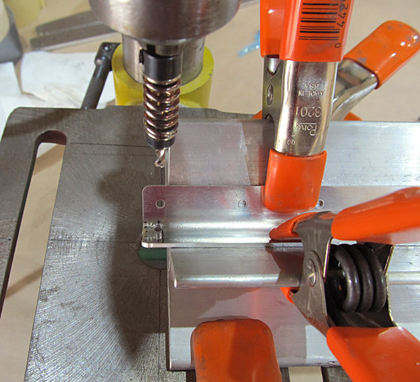
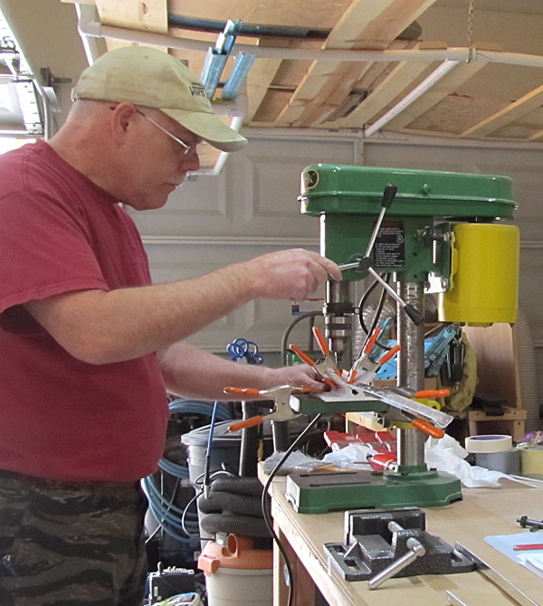
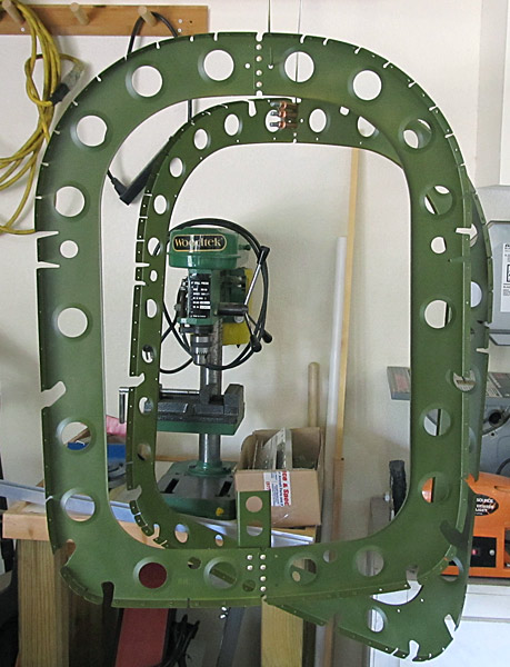
 The two horizontal stabilizer attach bars (F-01410C's) need to have the upper center #30 hole enlarged to 1/4" and this must be done using the drill press. |
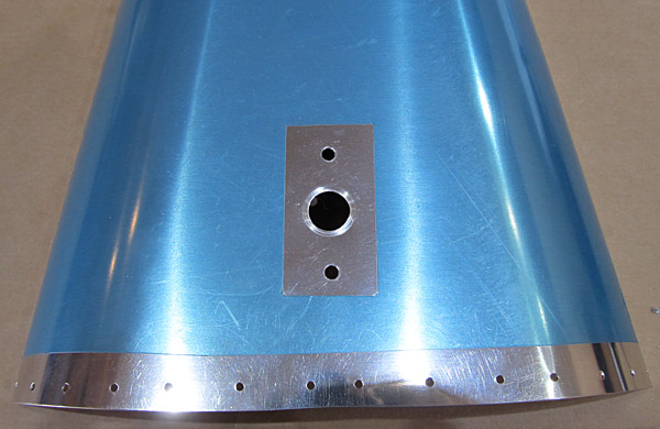
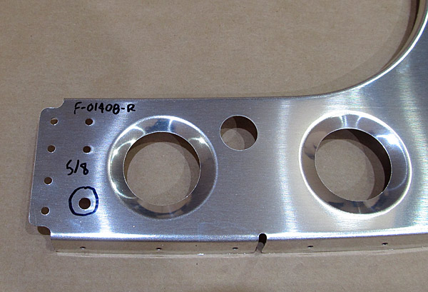
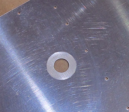
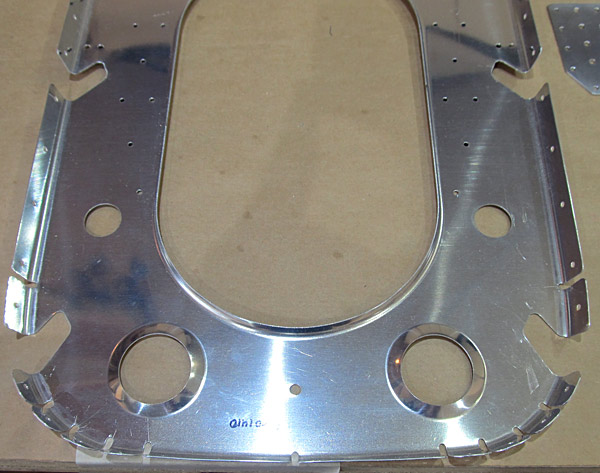 There is a hole at the bottom of bulkhead (F-01410) that needs to be enlarged to 5/8". |
|
|
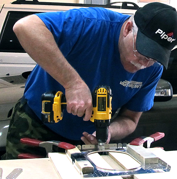
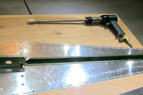
The "systems hole" is to be enlarged using a step drill bit. |
|
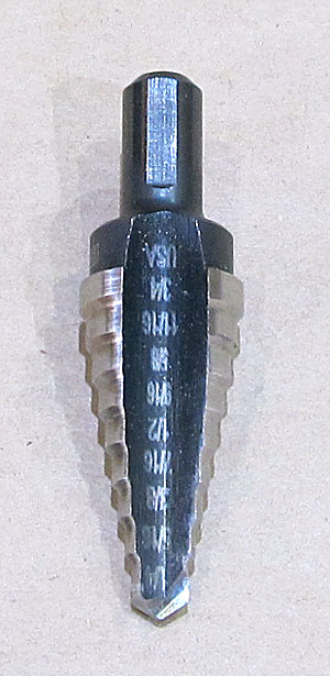 This is the step drill bit I used. |
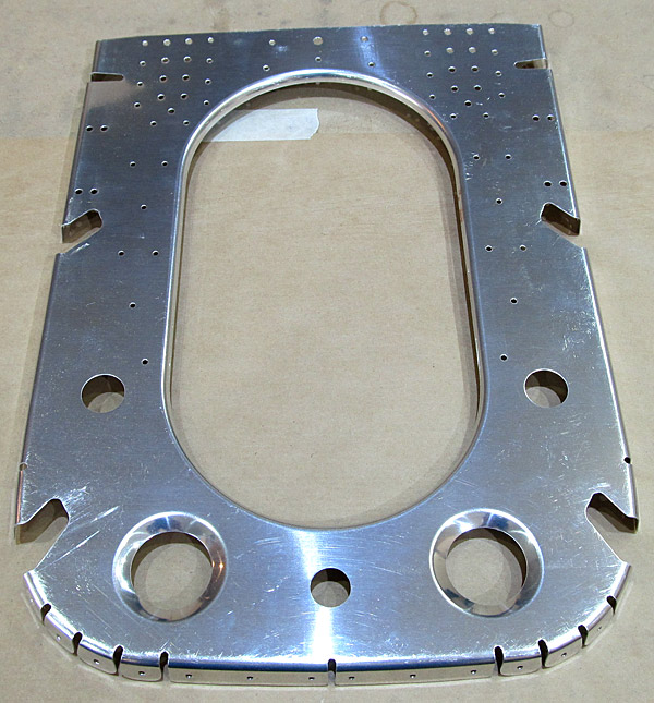
 Since I had the step drill bit out and I knew that a hole had to be enlarged on the aft bottom skin (F-01479) I went ahead and marked the holes that needed to be enlarged. |
 After enlarging the holes I deburred them. |
|
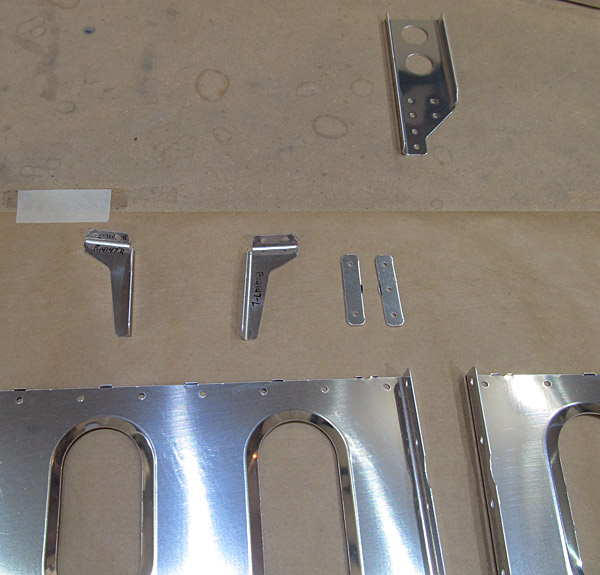
 The two doublers (F-01410B's) and the two horizontal stabilizer attach bars (F-01410C's) were edge deburred with a flat file and surface scuffed with ultra fine scotchbrite pads in preparation for priming. |
|
|
The bulkhead doubler (F-01410A) was edge deburred and the surface scotchbrited in preparation for priming. |
|
|
The bulkhead (F-01410) was edge deburred and the surface scotchbited in preparation for priming. |
 The bulkhead (F-01410) and the aft bottom skin (F-01479) were clecoed together and the bottom flange of bulkhead (F-01410) was fluted to fit properly into the aft bottom skin. |
 All of the #40 flange holes (except the four holes in the top two tabs) were dimpled. |
 All of the parts were washed with acetone and primed with Tempo A702 zinc phosphate primer. |
 Bulkheads (F-01407-L and F-01407-R) are next to be worked on... |
 Although the plans in section 10 never really mention to debur anything I wanted to show a closeup of what the edges of the metal looks like. |
 I final reamed all of the #40 and #30 holes in bulkhead (F-01407-L) and then scuffed the surfaces with ultrafine scotchbrite pads in preparation for priming. |
 All of the #40 holes in the flanges of bulkhead (F-01407-L) were dimpled using our hand squeezer equipped with a 3/32" sub-structure die installed. |
 I washed the left bulkhead down with acetone to get it ready for primer. |
 I primed the bulkhead (F-01407-L) with Tempo A702 green primer. |
 The right half of the bulkhead (F-01407-R) is next....pretty much the mirror image of the left. |
 There's those pair of holes on the flanges that don't get dimpled. |
 After all of the #30 and #40 holes have been final reamed, deburred, and dimpled I washed the bulkhead (F-01407-R) with acetone and get it ready for primer. |
 I primed the bulkhead (F-01407-R) with Tempo A702 green primer. |
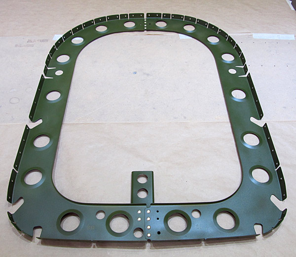
 The (F-01410) bulkhead assembly is next on the assembly list. |
 There are three different sized rivets used to complete the construction of this bulkhead so make sure to reference the builder's plans to correctly place the rivets. |
 When it came time to set the AN470AD4-8 rivets to hold the horizontal stabilizer attach bars (F-01410C), I had to switch to a thinner "domed" rivet set in order to have the proper gap distance to properly set the rivet. |
 The completed (F-01410) bulkhead assembly. |
 We clecoed the two bulkhead halves (F-01407-R and F-01407-L) together next in preparation for riveting. |
 *There are three rivets in the top of the bulkhead that don't get riveted at this time so make sure to pay attention here! |
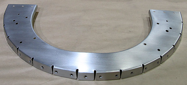
Bulkhead F-01408 is the subject of Service Bulletin 18-09-17
Empennage kits shipped after 9/26/2018 are not affected by this service bulletin but since mine was shipped in the spring of 2017 the service bulletin needs to be complied with.
 The service bulletin deals with cracks discovered in the aft fuselage bottom skin in the area of bulkhead (F-01408). |
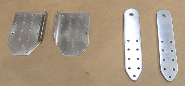
 The (F-14147-L and F-14147-R) stiffener clips and the (F-14148B and F-14148C) stiffener doublers need to be separated so I did that on the bandsaw. |
 Since I was going to be using the bandsaw, I got the (F-01429) bellcrank ribs out and separated them as well. |
|
 All separated! |
 A closer view.... |
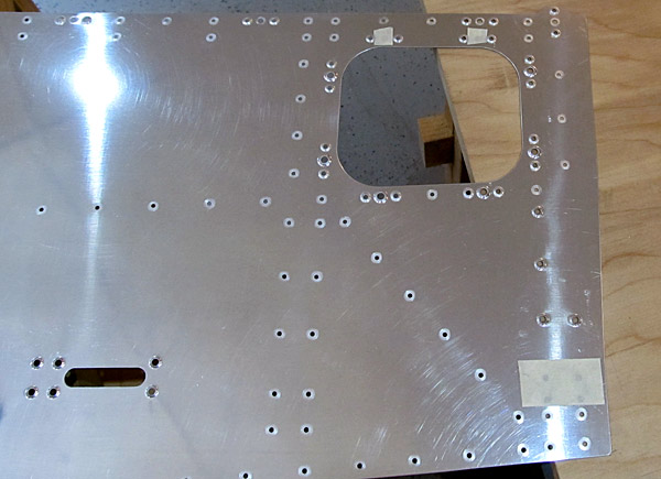
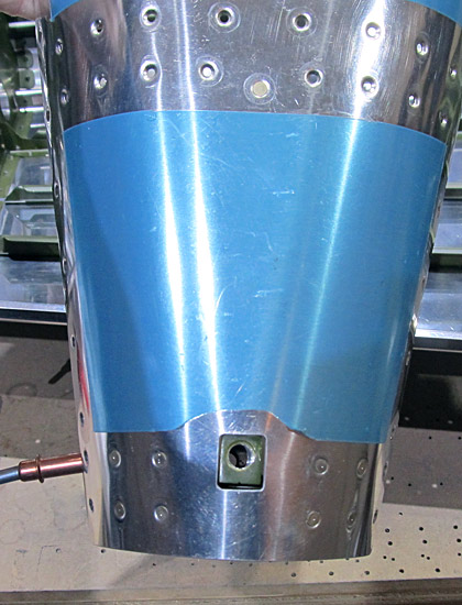
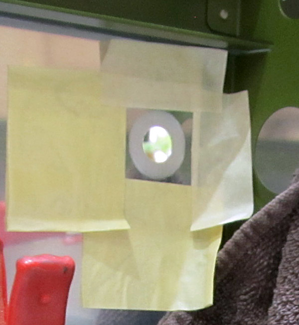
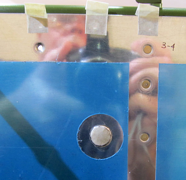
 The systems hole on (F-01408-R) needs to be enlarged to 5/8". |
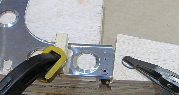 I supported the bulkhead half well because when using the step drill a lot of torque can develop and I didn't want any "accidents"! |
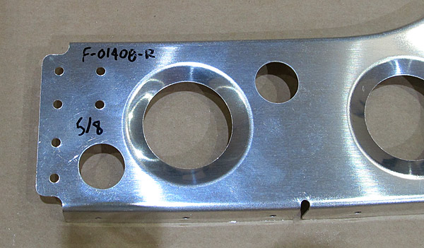 Here is the enlarged systems hole. |
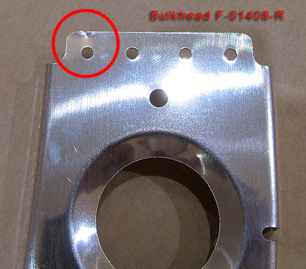 On a side note, after I removed the blue vinyl from the bulkhead half I noticed the small dent at the edge of the metal. |
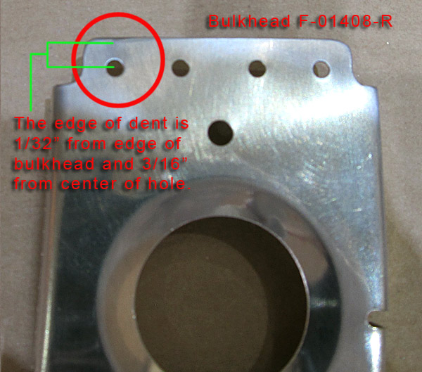 They said to "dress it out", since it wasn't very deep, and to build on! |
 Here is (F-01408-R) after deburring and scuffing with ultra fine Scotchbrite pads ready for the dimpling of the #40 holes in the flanges. |
 There are three holes in the bulkhead half that do not get dimpled. |
 This hole is on the bottom flange of (F-01408-R) and is where the service bulletin SB-18-09-17 (F-14148A) skin doubler will be attached and riveted later in construction. |
 I used the hand squeezer with 3/32" sub-structure dies installed to make the dimples. |
 Dimpled! |
 The (F-14115) rudder cable bracket was deburred and scuffed next in preparation for priming. |
 Now to start the process over again, this time I am working on (F-01408-L) bulkhead half...pretty much a carbon copy process of the right half! |
 These are the two holes that don't get dimpled on (F-01408-L) bulkhead because later on in construction longeron (F-01418B-L) will go here. |
 Dimpling complete! |
 Dimpling complete! |
 After the dimpling process was completed all of the parts were primed with Tempo A702 green primer. |
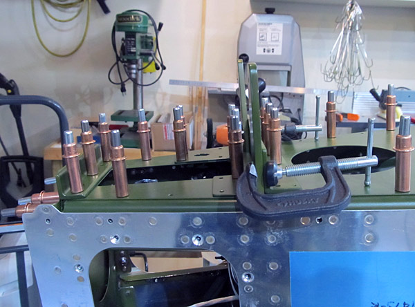
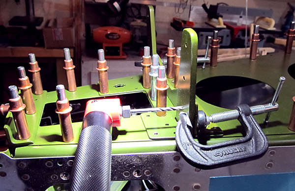
 We found that clamping the assembly to the bench made the job easier to do. |
|
 Riveting complete! |
 Step six in the plans calls for machine countersinking of all of the #40 nutplate attach holes in the two battery angles (F-01437B and F-01037C) after they have been final drilled to size. |
 I primed the two battery angles (F-01437B and F-01037C) with Tempo A702 green primer paint. |
 I final reamed all #30 and #40 holes and deburred the edges of all of the SB-18-09-17 service bulletin parts. The two stiffener clips (F-14147-R and F-14147-L) are to have the #40 holes dimpled. |
 The edges of the (F-14148A) skin doubler was deburred and then beveled according to the service bulletin and then all of the #40 holes on the surface of the doubler were machine countersunk to accept a head of a AN426AD3 type rivet. |
 The SB-18-09-17 service bulletin parts were washed with acetone and then primed with Tempo A702 green primer. |
 I final reamed all of the #30 and #40 holes in the bellcrank ribs (F-01429-L and F-01429-R) |
 Nice! |
 The bellcrank ribs (F-01429-L and F-01429-R) forward end flanges have #30 holes but only the top hole is dimpled, the rest remain "un-dimpled". |
 I dimpled all of the #40 holes in the bottom flanges of the bellcrank ribs (F-01429-L and F-01429-R) using our hand squeezer. |
 The bellcrank ribs (F-01429-L and F-01429-R) were washed with acetone in preparation for priming. |
 Both of the bellcrank ribs were primed with Tempo A702 green primer. |
 The next item to work on is the aft bulkhead (F-01406B) and just like everything else, got to remove the protective blue vinyl! |
 I final reamed all of the #30 and #40 holes on the aft bulkhead (F-01406B) and deburred all of the edges. |
 I scuffed all of the surfaces on the aft bulkhead (F-01406B) with Scotchbrite ultra fine pads before the dimpling process began. |
 There are #30 and #40 holes in the bulkhead (F-01406B) that require dimpling and I used our DRDT2 and also a hand squeezer to do the job. |
 The aft bulkhead (F-01406B) was washed with acetone in preparation for priming. |
 I primed the aft bulkhead (F-01406B) with Tempo A702 green primer. |
 There is an angled nutplate (MS21055L08) that needs to be dimpled before being attached to the aft bulkhead (F-01406B) and I used our DRDT2 to do the job. |
 Time to do some riveting! |
 Manufactured heads to the top. |
 The battery angles (F-1037B and F-1037-C) are then riveted to the bellcrank ribs (F-01429-L and F-01429-R) using AN470AD4-4 rivets which we set using our pnuematic squeezer. |
 The various nutplates are then riveted to the aft bulkhead (F-01406B) using our hand squeezer to set them in place with AN426AD3-3.5 rivets making sure that the manufactured heads were located on the forward and top sides of the bulkhead. |
 We clecoed the bellcrank rib assemblies (F-01429-L and F-01429-R) to the aft bulkhead (F-01406B) so that they could be riveted together. |
 It looked like using the 3x rivet gun and a tungsten bucking bar was our best option to set the AN470AD4-4 rivets so we clamped everything to the table before we started. |
 All set! |
|
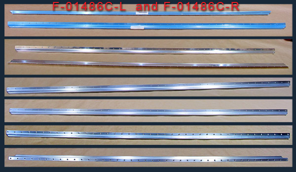 The stiffeners (F-01486C-L and F-01486C-R) were the next items to start working on. |
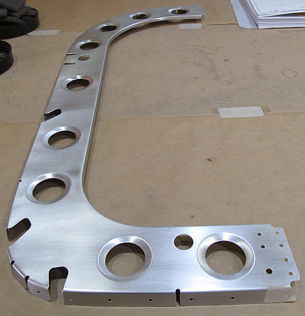
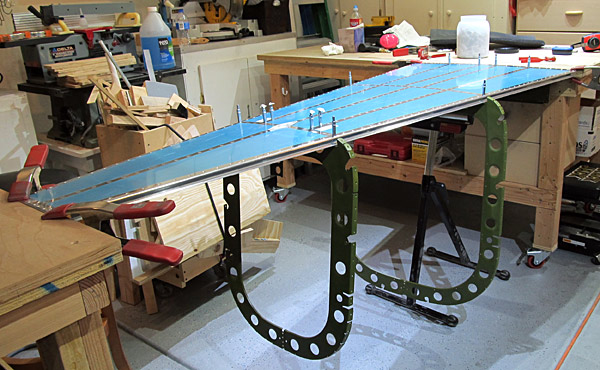
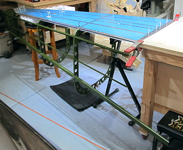
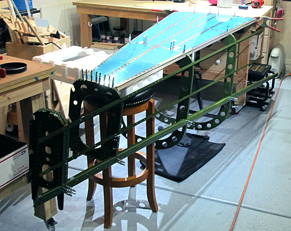
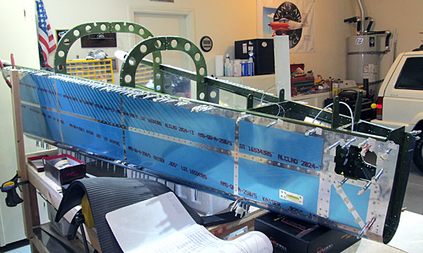
At this point I am deviating from the plans only in the sense that I am going to concentrate on getting all of the rest of the tailcone parts deburred and primed. From this point on the project starts to get really big (almost eight feet long) and if I start to rivet the frame and skins now I won't have enough workbench space later to do the debur work with the tailcone in the way.
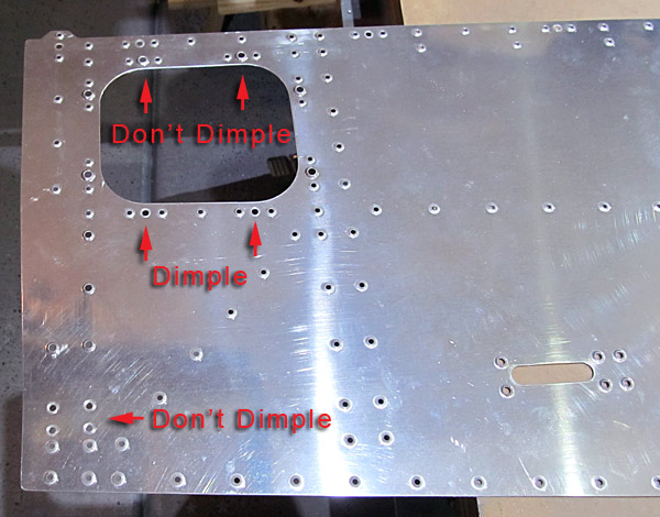
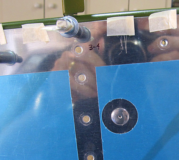
 All of the #40 holes in the aft fuselage stiffeners flanges (F-01486C-R and F-01486C-L) need to be dimpled. I started to do that here using our DRDT2 after all of the surfaces have been scuffed in preparation for priming. |
 If you have an empennage kit that was shipped before 9/26/2018, then you have to pay attention to the holes that are not supposed to be dimpled at this time (according to SB 18-09-17) that is why I taped the two holes on each of the stiffeners (F-01486D and F-01486E) as shown here. |
 The stiffeners (F-01486C-L and F-01486C-R) were washed with acetone and then primed with Tempo A702 green primer. |
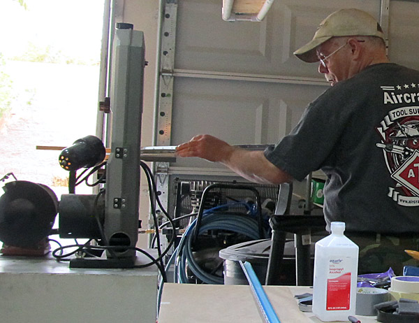
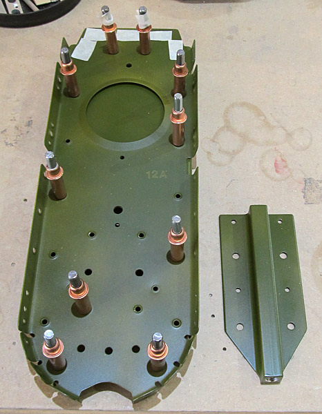
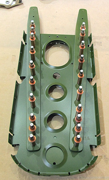
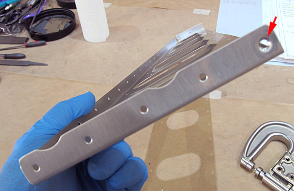
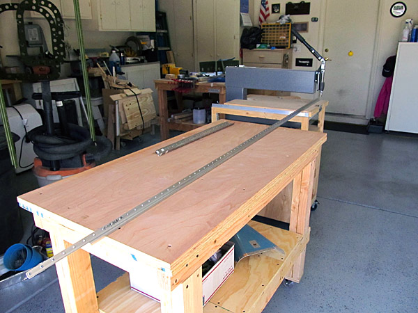
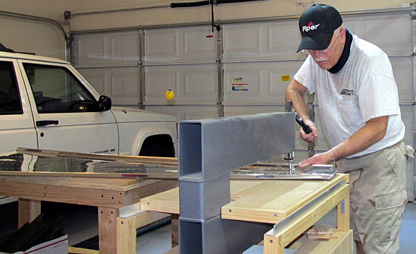
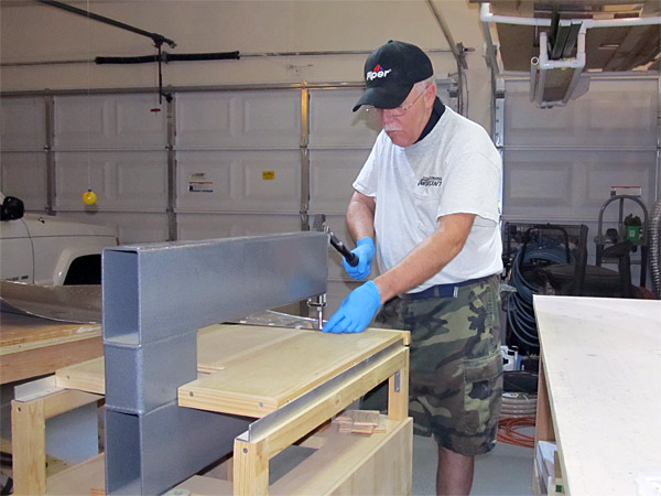
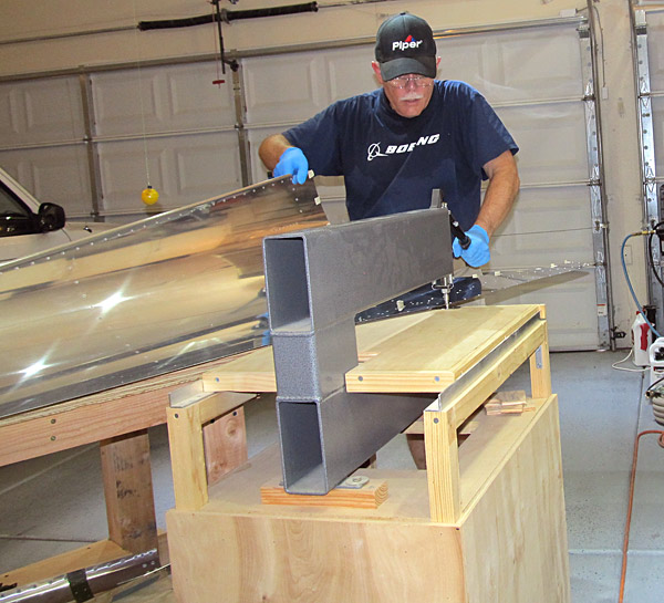
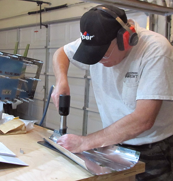
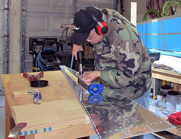
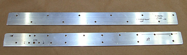 In preparation for the machine countersinking process that would come next on the longerons, I made a few guide blocks so that when the countersinking began I would not get any "wobbling" as the countersink got deeper into the metal....just a little more of a guide for the nipple on the countersink head. |
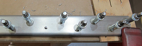 The clecos hold the guide block in place and what you get is a nice clean countersink! |
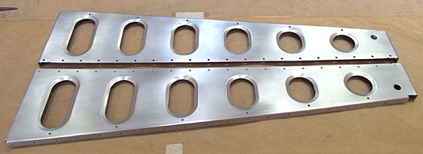
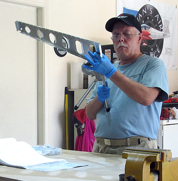
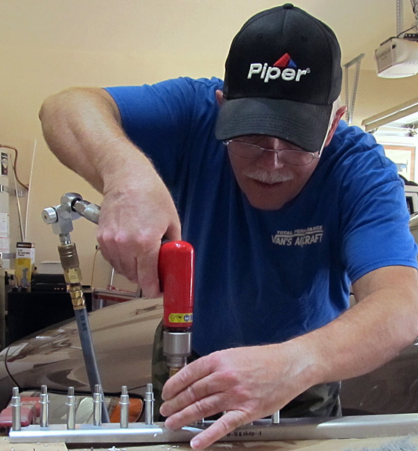 Let the machine countersinking of the longerons (F-01418B-L and F-01418B-L) begin! |
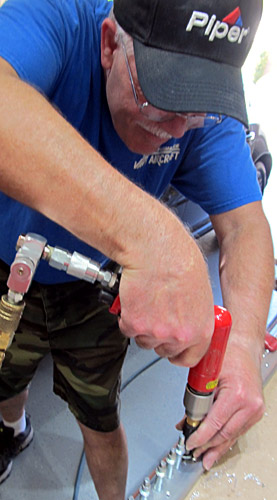 It is nice to have the piece clamped to the table as well. |
 Remember the stiffeners I dimpled yesterday? Today I primed them with Tempo A702 primer green. |
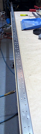 Finally, all of the #40 holes in the longerons (F-01418B-L and F-01418B-R) have been machine countersunk so that a #40 sized dimple of the overlying skins will fit nicely. |
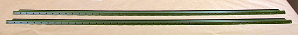
 The long stiffeners (F-01486A-L, F-01486A-R, F-01486B-L and F-01486B-R) have been washed with acetone and primed with Tempo A702 primer green. |
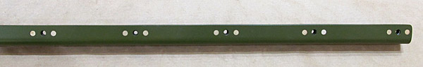
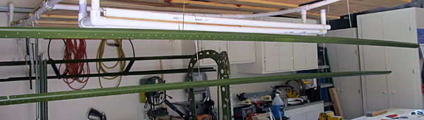 The longerons (F-01418B-L and F-01418B-R) were washed with acetone and primed with Tempo A702 primer green. |
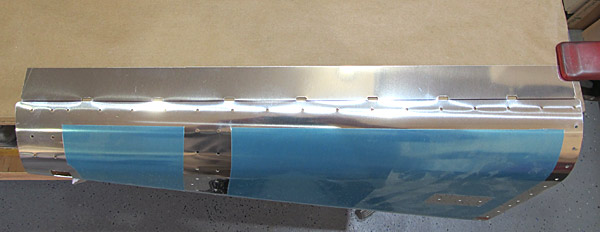
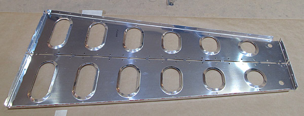
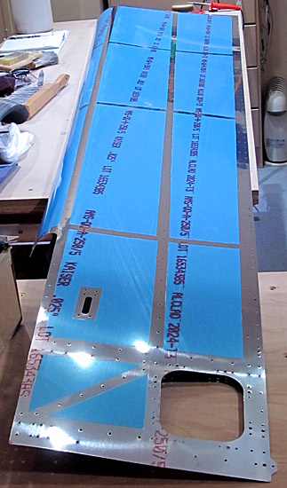
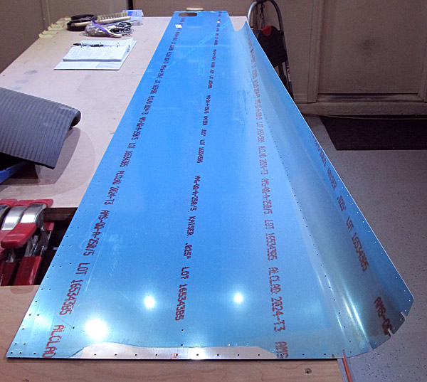
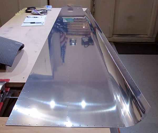
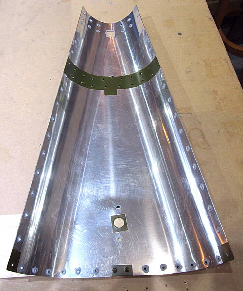
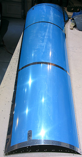
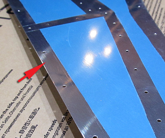
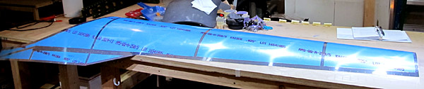
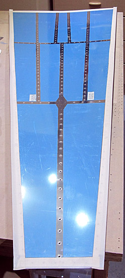
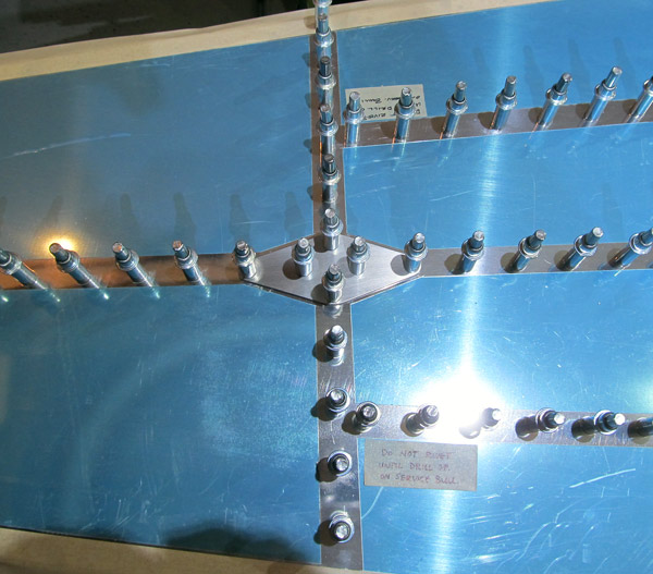
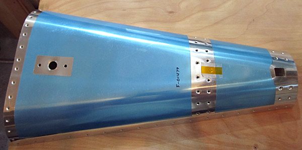
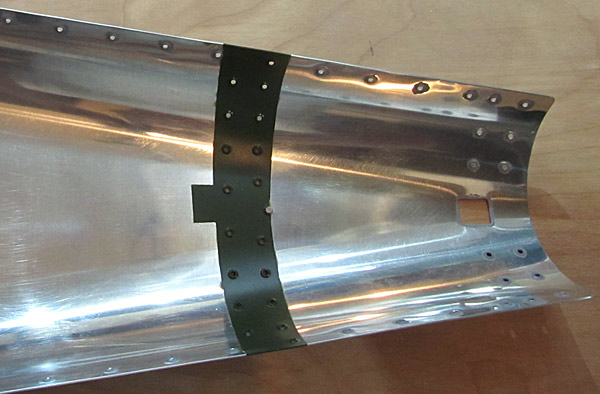
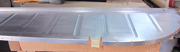
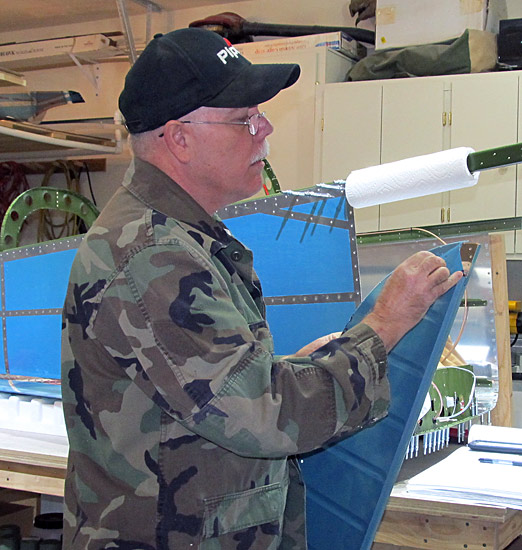
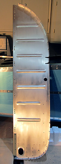
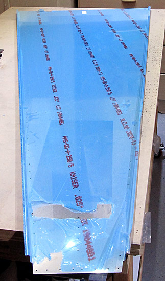 Time to remove the protective blue vinyl from the aft fuselage bottom skin (F-01478). |
|
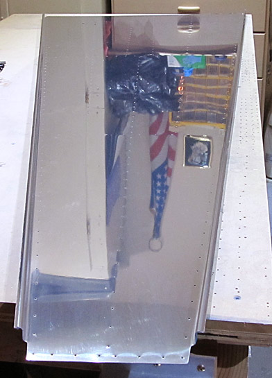 Bare metal! |
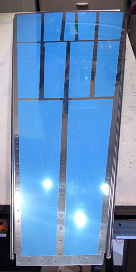 Some don't like to section the blue vinyl from the skins but I still do it because otherwise too many scratches result. |
 In this photograph you can see the diamond shape of where the skin doubler will go in order to comply with Service bulletin SB 18-09-17. |
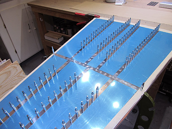
 All of the #40 holes were final reamed with a number 40 reamer and then scuffed with ultrafine ScotchBrite pads so that later they can be primed. |
 The deburring process begins on the edges of the bottom skin (F-01478). |
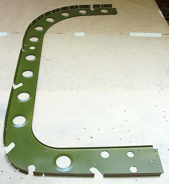
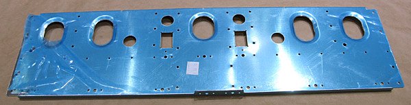
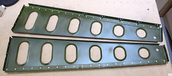
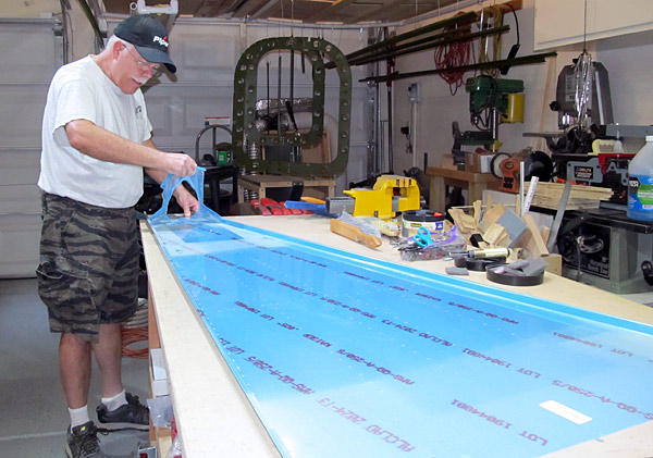
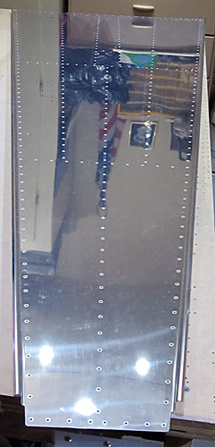
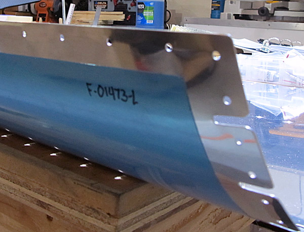
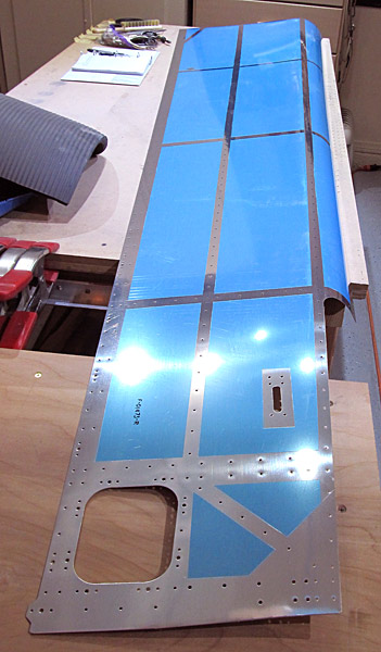
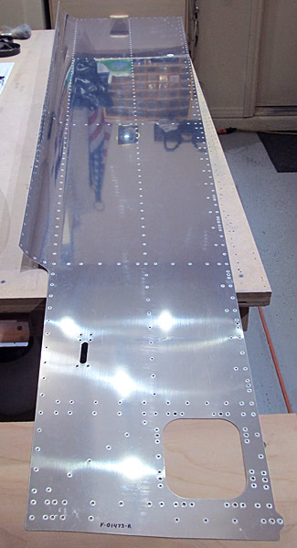
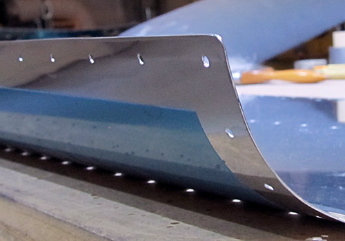
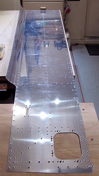
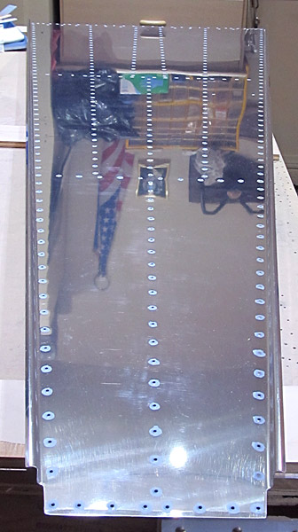
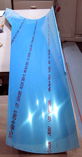
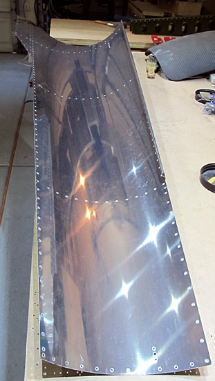
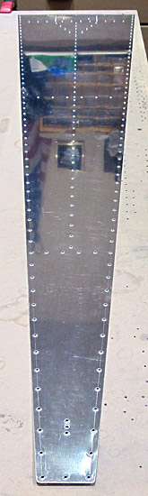
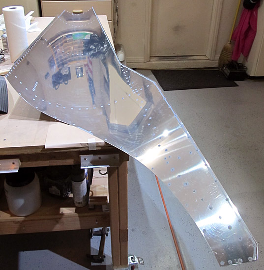
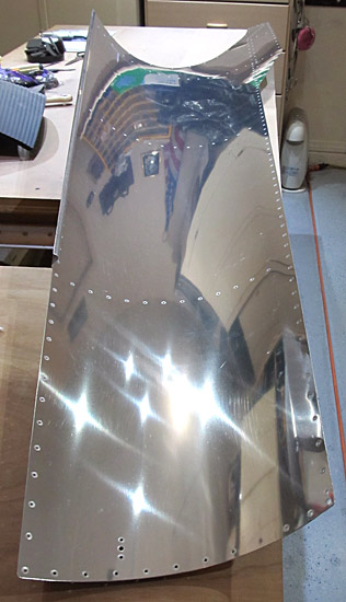
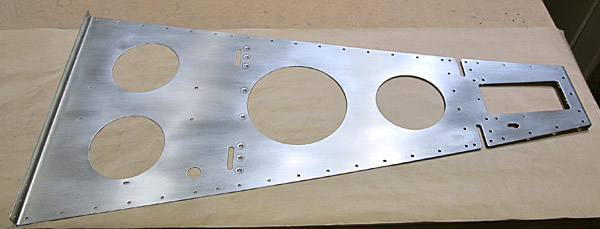
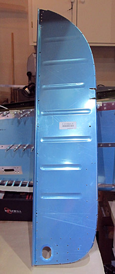
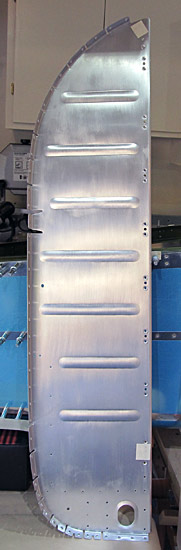
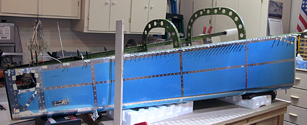
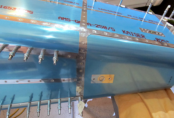
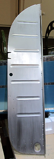
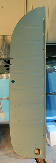
 I sectioned off the protective blue vinyl on the aft fuselage left side skin (F-01473-L). |
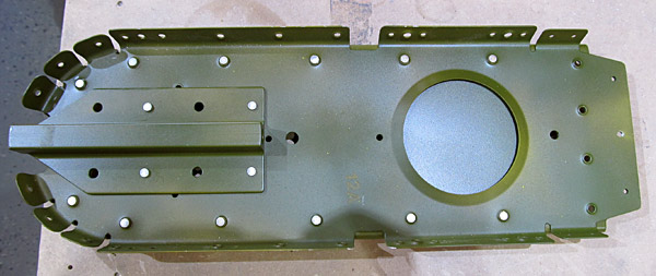
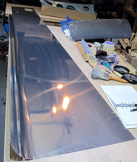 The inside of the aft fuselage left side skin (F-01473-L.) |
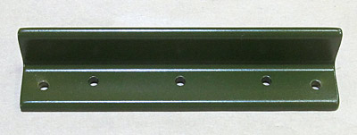
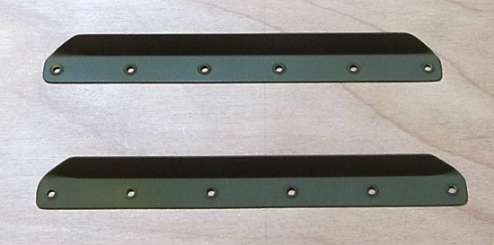 A closer look at the primed (F-01473A) stiffener angles. They will be located at the aft end of the tailcone section under the inspection covers. |
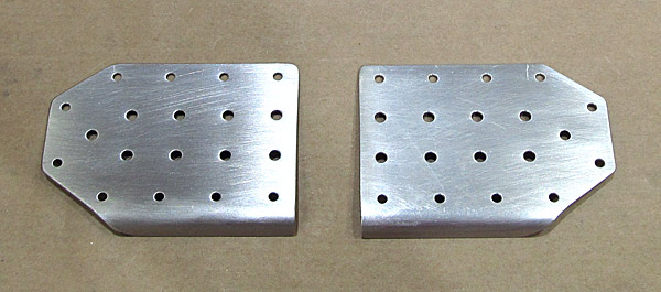
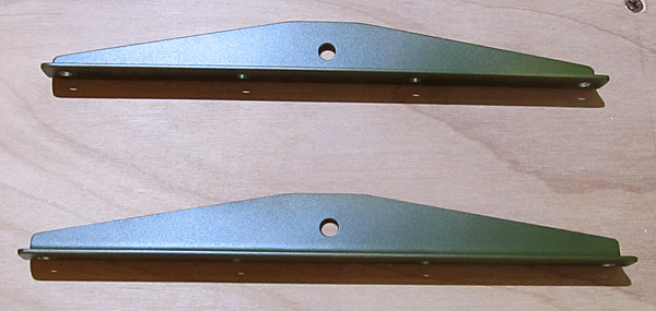 These are the (F-1037A) battery angles. |
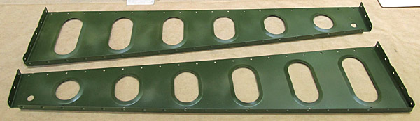
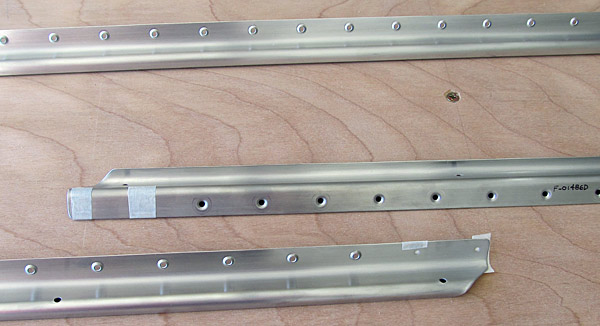
 These are the stiffeners (F-01486D, F-01486E, and F-01486F). |
 These are the (F-01486C-L and F-01486C-R) stiffeners. |
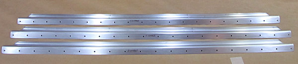
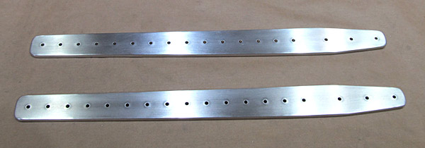
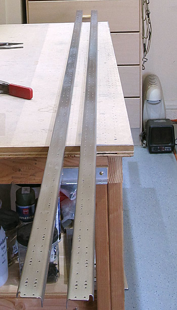
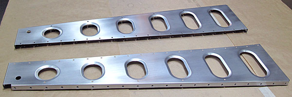
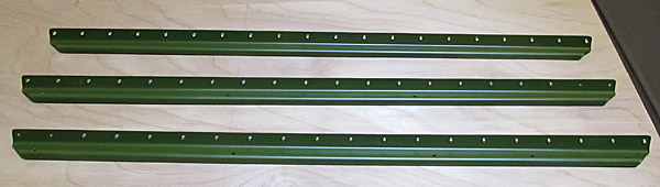
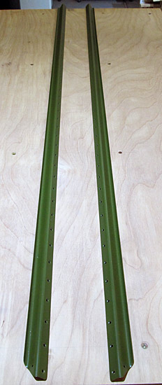
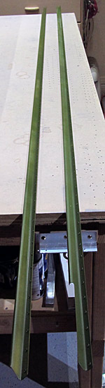
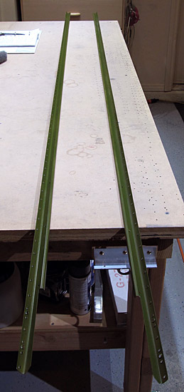
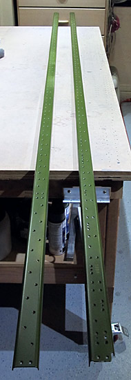 These are the longerons (F-01418B-L and F-01418B-R). |
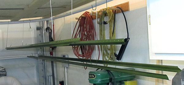
 This is one pair of side stiffeners (F-01486B-L and F-01486B-R). |
 This is one pair of side stiffeners (F-01486A-L and F-01486A-R). |
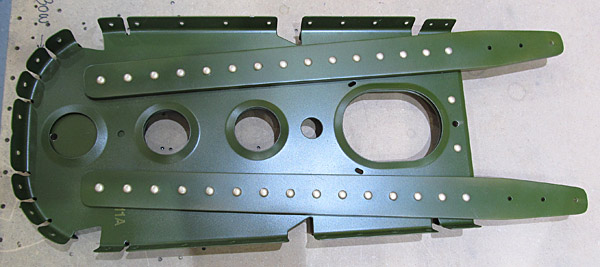
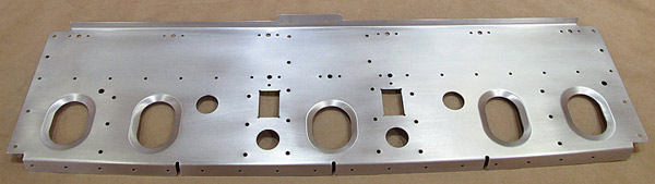
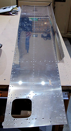
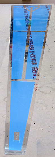
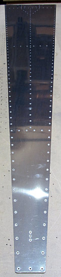
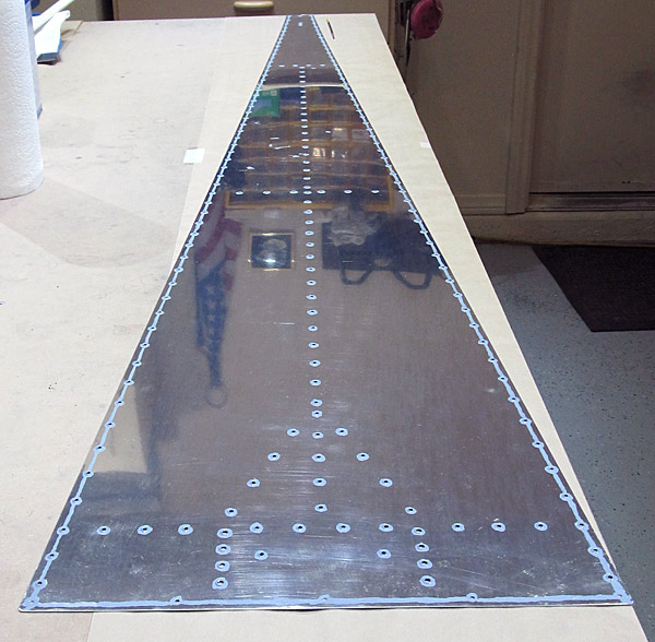
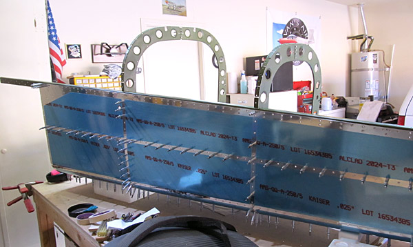
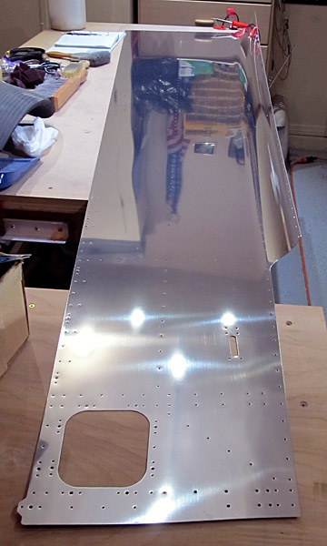 All of the holes in the aft fuselage left side skin (F-014873-L) have been final sized and the edge deburring has begun. |
 I like to scuff around the #40 holes with ultrafine Scotch Brite pads so that I can prime in only those areas and hopefully save some weight by not painting the whole interior, but it is a lot of work and time consuming. |
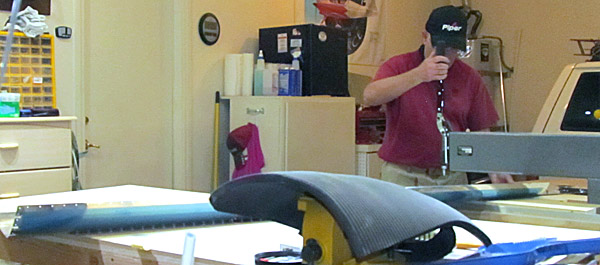
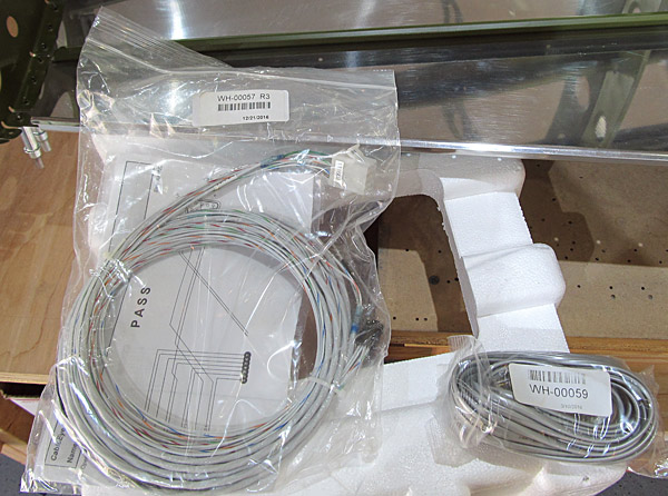
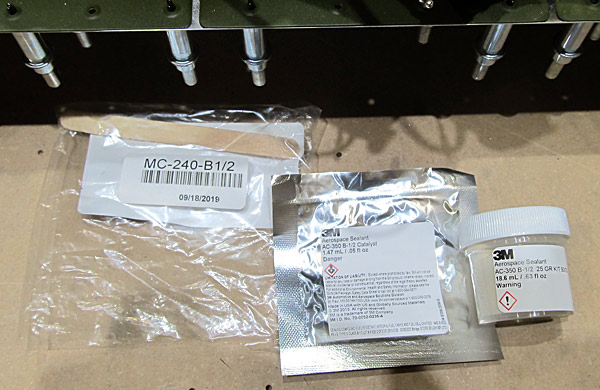
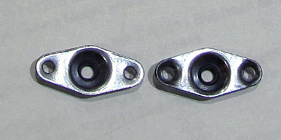
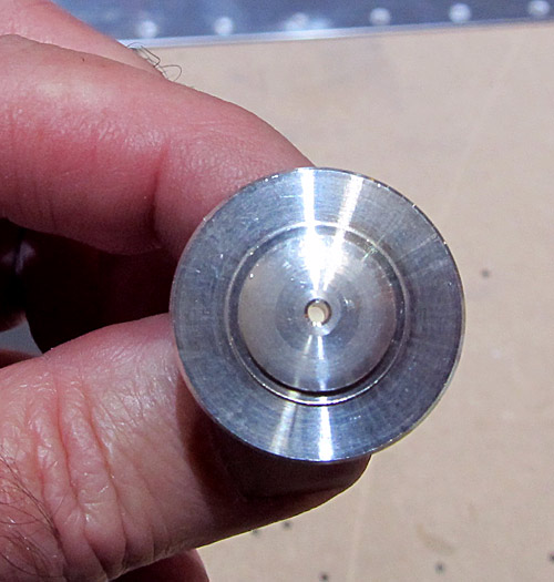 I have elected to use a different static port than the one used as standard from Van's. |
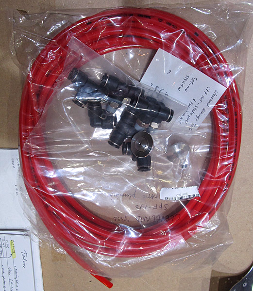 Here is what is included in the Cleaveland Aircraft Tools static port conversion kit. There are two static ports, several quick connect junctions, and new static port lines. |
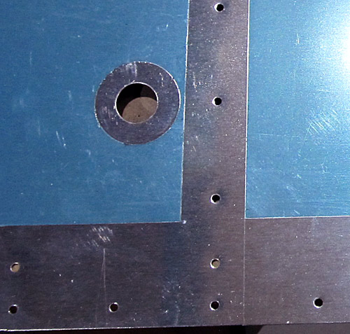
 The 1/8" hole in the side skin has to be enlarged to 1/2" using a unibit so that the new static port can sit recessed in the skin. |
 Once the hole has been enlarged the area around it has to be scuffed with 150 grit aluminum oxide sandpaper because the port will be adhered to the skin with tank sealant or RTV adhesive. |
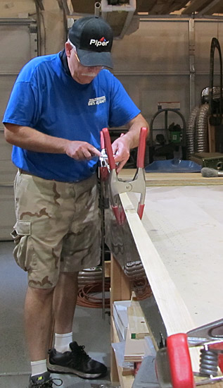
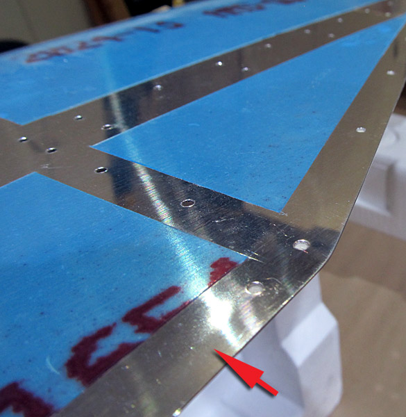
 I put an edge break on the lower edge of the aft fuselage left side skin (F-01473-L) so that when the side gets riveted to the bottom skin there will be a nice tight seam. |
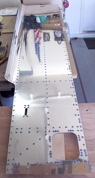
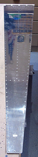
 All of the #40 holes in the left side skin (F-01473-L) were dimpled. *Be sure to use a small diameter female die set in the curved areas in order to minimize distortion. |
 I didn't discover a mistake I made in dimpling the #27 holes until I was editing the photographs for this blog post but apparently I dimpled two holes I wasn't supposed to dimple and didn't dimple two holes that I was supposed to dimple. |
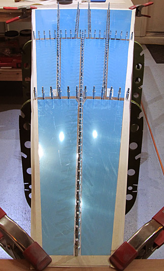
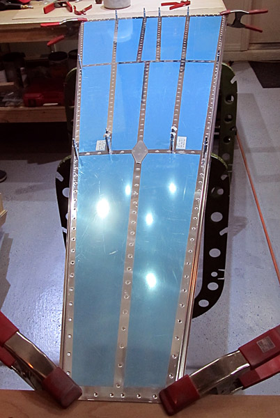
 I dimpled all of the #40 holes in the aft fuselage bottom skin (F-01478) with the exception of the six holes that Service Bulletin SB 18-09-17 affects. |
 I used the DRDT2 to make the dimples. |
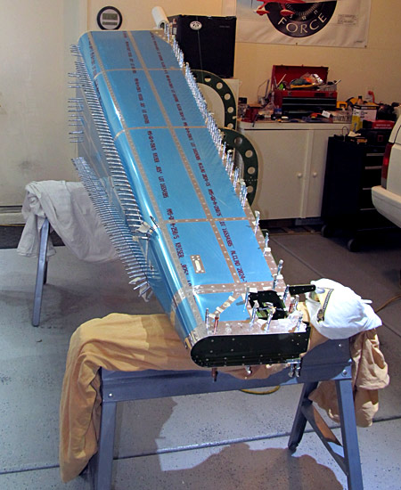
 Here it is all dimpled! |
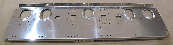
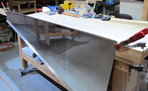
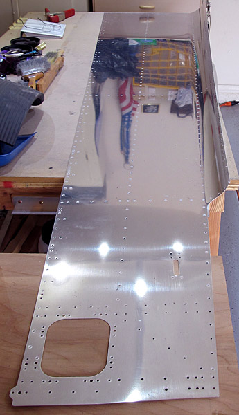
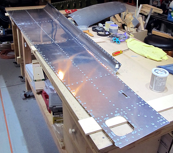
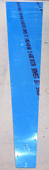
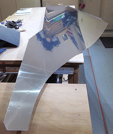
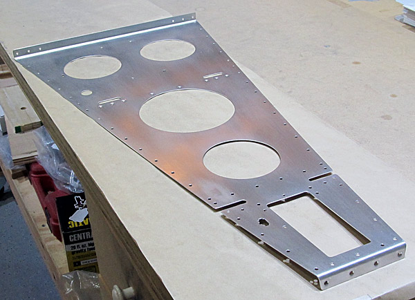
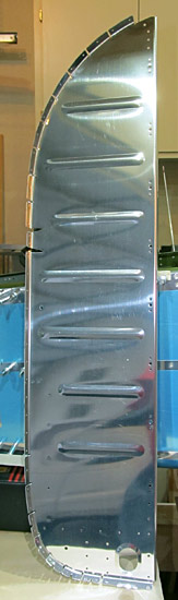
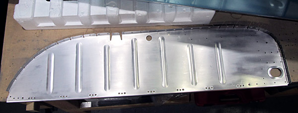
 I am about to take off the blue protective vinyl from the aft fuselage right side skin (F-01473-R). |
 Bare metal! |
 Just like the left side skin, I sectioned off the blue vinyl on the aft fuselage right side skin (F-01473-R). |
 I enlarged the 1/8" hole for the right side static port to 1/2" using a unibit. |
 The inside of the aft fuselage right side skin (F-01473-R) was scuffed using 150 grit aluminum oxide sandpaper so that the new static port can be adhered to the skin. |
 All of the holes on the aft fuselage right side skin (F-01473-R) were final sized and deburred. I also scuffed around the holes with ultrafine Scotch Brite pads in preparation for priming. |
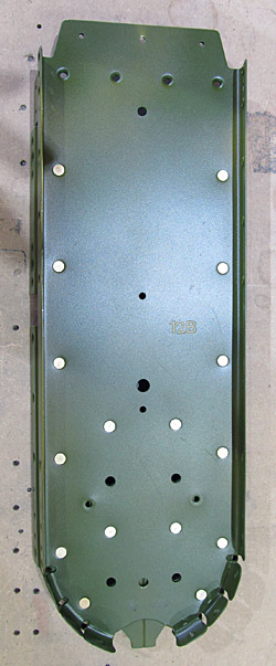
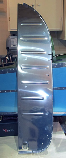
 I scuffed around the holes of the aft fuselage bottom "tailskid" skin (F-01479) in preparation for priming |
 I dimpled all of the #40 holes in the aft fuselage bottom "tailskid" skin (F-01479) using the DRDT2 making sure to have a reduced diameter female die set installed so that when dimpling in the curved sections distortion would be minimized. |
 I started to debur the bottom edge of the aft fuselage right side skin (F-01473-R). |
 I put an edge break on the bottom edge of the aft fuselage right side skin (F-01473-R). |
 I washed the inside areas of the aft fuselage bottom "tailskid" skin (F-01479) with acetone and then I primed the middle bulkhead area with Tempo A702 primer green. |
 I started dimpling the #27 holes around the inspection cover opening on the aft fuselage right side skin (F-01473-R) and this time I payed particular attention to dimpling the holes I was supposed to dimple and not dimpling the holes I'm not supposed to....don't want to make that mistake again! |
 I used the DRDT2 to make most of the #40 dimples making sure to use a reduced diameter female die set in the curved sections. |
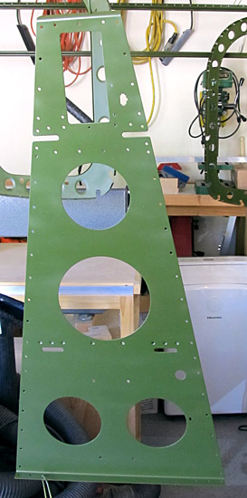
 All of the holes in the aft fuselage right side skin (F-01473-R) have been dimpled. |
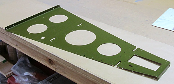
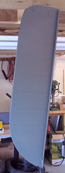
 I primed around all of the holes in the aft fuselage right side skin (F-01473-R) after first washing everything with acetone. |
 I primed around all of the holes in the aft fuselage left side skin (F-01473-L) after first washing everything with acetone. |
 I primed around all of the holes in the aft fuselage bottom skin (F-01478) after first washing everything with acetone. |
 Time to correct the mistake I made on the aft fuselage left side skin (F-01473-L). |
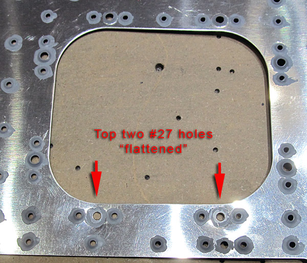 The results didn't look too bad so next I flattened the #27 dimples on the aft fuselage left side skin (F-01473-L) around the inspection cover opening that we were talking about. |
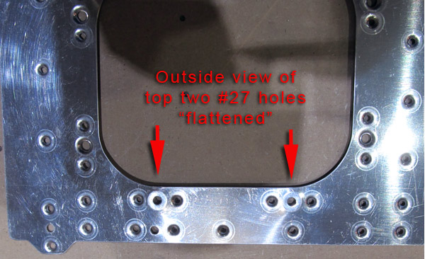 This is what the flattened dimples look like from the outside. |
 Now it's time to remove the protective blue vinyl from the aft fuselage right top skin (F-01474-R). |
 I know it takes extra time to section out the protective blue vinyl, but to me it is worth it because these skins get plenty of scratches on them when moving them around on the bench and when dimpling them. |
 The aft fuselage top center skin (F-01475) is next. |
 The outside of the aft fuselage top center skin (F-01475) gets sectioned off too. |
 I scuffed around all of the holes in the aft right top fuselage skin (F-01474-R) with Scotch-Brite ultrafine pads in preparation for priming. |
 The aft fuselage top center skin (F-01475) holes were Scotch-Brite scuffed in preparation for priming. |
 I clamped the aft fuselage top center skin (F-01475) to the workbench and deburred the edges using a hand file. |
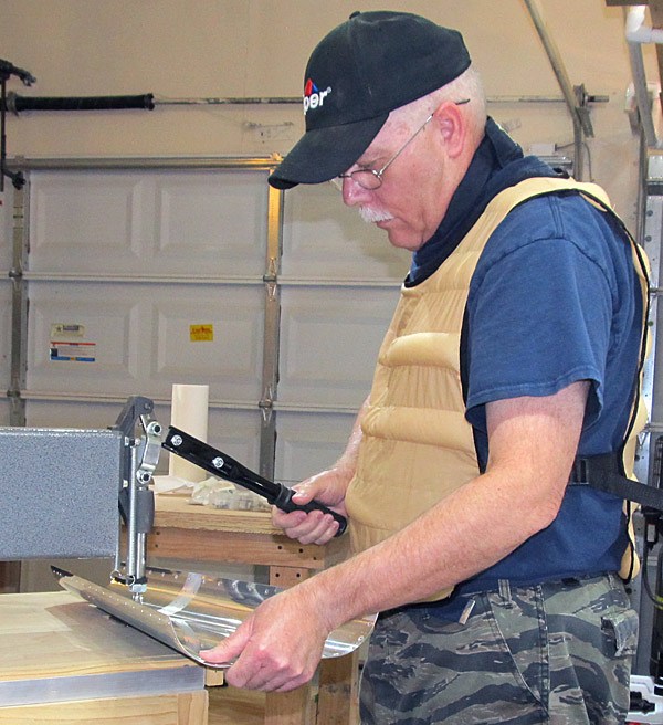
 Before I dimple the aft fuselage top center skin (F-01475), I put an edge break on both of the long sides and the aft edge of the skin using an edge rolling tool (per instructions in the manual on page 10-29, figure 1.) |
 The aft fuselage top center skin (F-01475) is now dimpled. I used our DRDT2 to make the dimples. |
 After finishing the edge deburring process on the aft fuselage top right skin (F-01474-R), I put an edge break on the lower side of the skin using our Cleaveland Air Tools edge roller. |
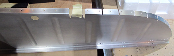
 There are several holes on the aft fuselage top right skin (F-01474-R) that do not get dimpled (see figure 1, page 10-30 in the builder's manual) so I placed some tape over them and began the dimpling process using our DRDT2. |
 Here is the dimpled aft fuselage top right skin (F-01474-R). |
 I washed the inside of the aft fuselage top right skin (F-01474-R) with acetone and primed the holes with PTI zinc phosphate primer. |
 I washed the inside of the aft fuselage top center skin (F-01475) with acetone and primed the holes with PTI zinc phosphate primer. |
 Time to start on the aft fuselage top left skin (F-01474-L) so off with the blue protective vinyl and sectioning the vinyl on the outside too. "DejaVu all over again!" |
 All of the #30, #40, and #27 holes were final reamed and deburred. |
 I scuffed all of the holes on the aft fuselage top left skin (F-01474-L) with Scotch-Brite pads and deburred all of the edges with a hand file. |
 After the edge debur was finished on the aft fuselage top left skin (F-01474-L), I put a slight edge break on the bottom side of the skin with an edge rolling tool. |
 Let the dimpling begin! |
 All of the #30 and #40 holes (except those that aren't supposed to be dimpled) have been dimpled on the aft fuselage top left skin (F-01474-L). |
 I washed the inside of the aft fuselage top left skin (F-01474-L) with acetone and primed all of the dimples with PTI zinc phosphate primer. |
 Now that all of the big parts have been dimpled, edge deburred, and primed it's time to move on to the smaller parts. |
|
|
|
|
 The (F-014111) empennage gap covers have been edge deburred and set aside. |
 This is the (F-01475A) skin doubler. All of the holes have been final reamed and deburred. The edges have been deburred and the surfaces have been Scotch-Brited in preparation for priming. All of the holes have been dimpled and I washed the part with acetone and priming is next. |
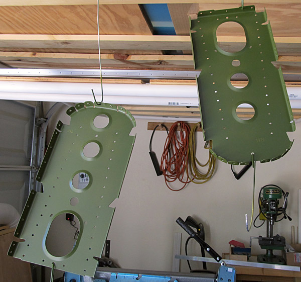
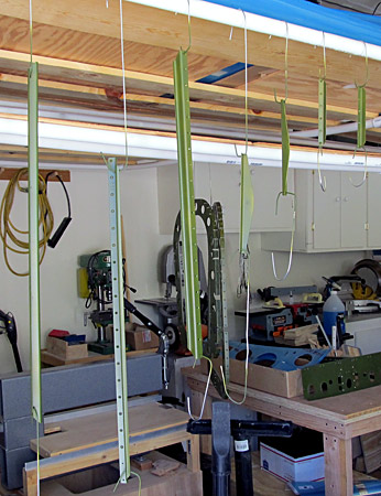
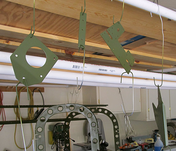 After priming the parts, I like to let them hang to dry for a couple of days before handling them. |
 This is the (F-01411E) deck doubler primed with Tempo A702 primer. |
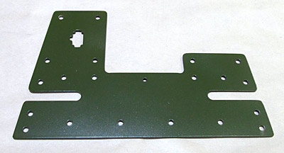
 This is the (F-01412C) deck angle. |
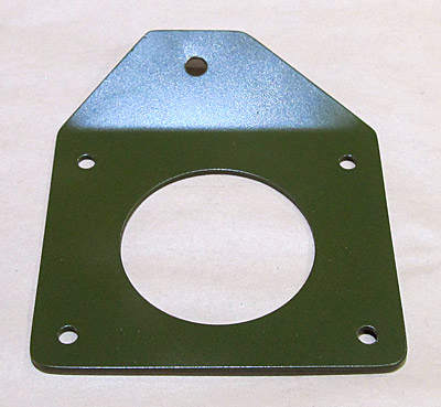 This is the (VS-01402) vertical stabilizer bracket. |
 This is the (F-01475A) skin doubler. |
 I finished edge deburring the upper aft fuselage rib (F-014131) and then scuffed all of the surfaces with Scotch-Brite ultrafine pads. |
 The upper aft fuselage rib (F-014131) was washed with acetone and is now ready for priming. |
 This is the (F-014131) upper aft fuselage rib after being primed with Tempo A702 primer. |
 I edge deburred the aft deck (F-01414) and then Scotch-Brited the surfaces with ultrafine pads in preparation for priming. |
 This photograph shows the holes that are to be dimpled a little better. |
 I primed the aft deck (F-01414) with Tempo A702 primer and hung it up for drying. |
 This is another photograph of the aft deck (F-01414). |
 I think that this is the last part to be worked on in preparation for priming. |
 The frame bulkhead (F-01409) was primed with Tempo A702 primer and hung to dry for a couple of days. |
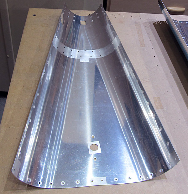
 This is another photograph of the frame bulkhead (F-01409). It's finally time to begin assembling the tailcone! Back to page 10-13, step one in the builder's manual. |
 Bulkhead (F-01407) was clecoed to the battery angle/bellcrank assembly in order to rivet them together with AN470AD4-4 rivets. |
 This photograph shows the four rivets that we were able to set using the pnuematic squeezer. |
 We had to use the 3X rivet gun equipped with a 1/8" cupped set and a tungsten bucking bar against the shop end. |
 Now it's time to rivet the aft fuselage bottom skin (F-01478) to the bulkheads and battery angle/bellcrank assembly so first we taped over the holes that do not get riveted at this time (see figure 1, page 10-13 in the builder's manual.) |
 The bottom skin (F-01478) is "strattled" across our two workbenches and then the bulkheads (F-01407 and F-01408) along with the battery angle/bellcrank assembly are clecoed into position. |
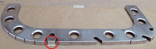
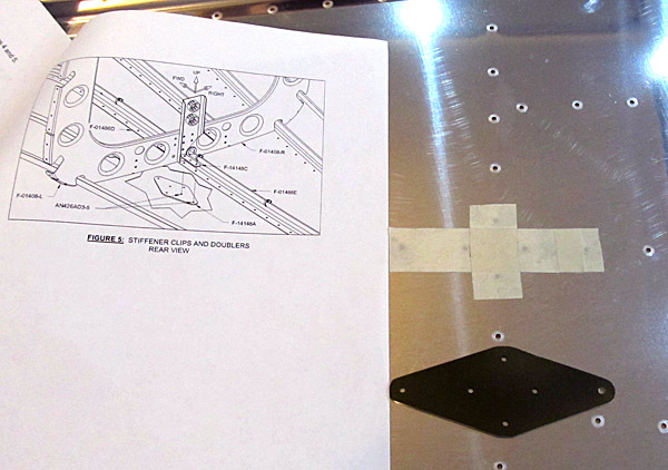
 This is a closer look at the service bulletin (SB-18-09-17) skin doubler (F-14148A,) diamond shaped plate, clecoed into place. |
 This is what everything looks like under the area shown in the photograph above. |
 This is the (F-14148C) stiffener clip that is clecoed to the (F-14148A) skin doubler overhead, just aft of the (F-01408) bulkhead. It too can be riveted in place at any time. |
 Let the riveting begin! |
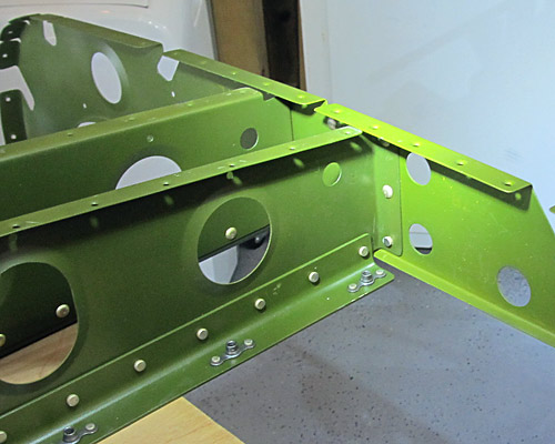
 We finished riveting the J-stiffeners, the bulkheads, and the battery angle/bellcrank assembly to the aft fuselage bottom skin (F-01478). |
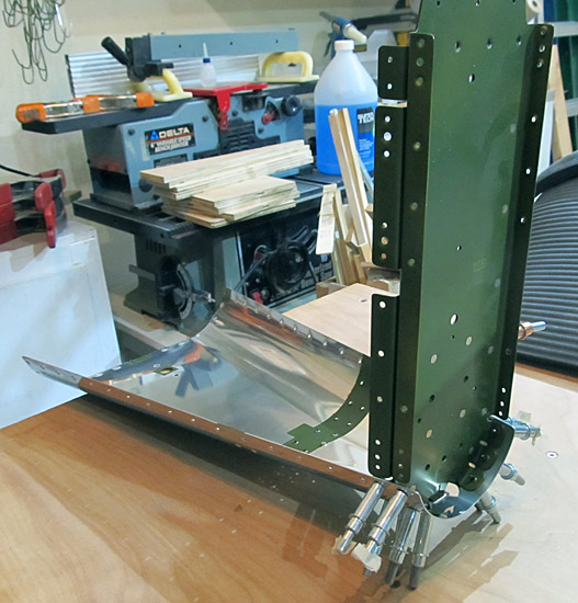
 Here is a side view of our setup. |
 Bulkhead (F-01410) was clecoed to the aft fuselage bottom skin (F-01478). |
 Bulkhead (F-01411) was clecoed to longeron (F-014718B-L). |
 Here it is on the workbench. |
 Another view looking towards the inside. |
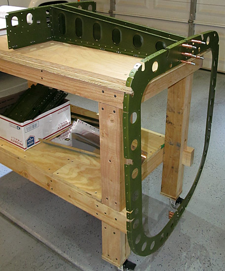
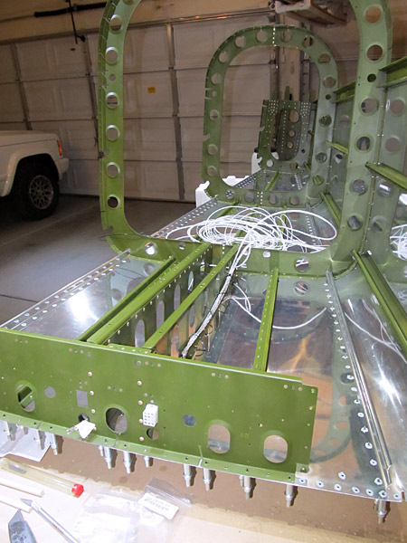
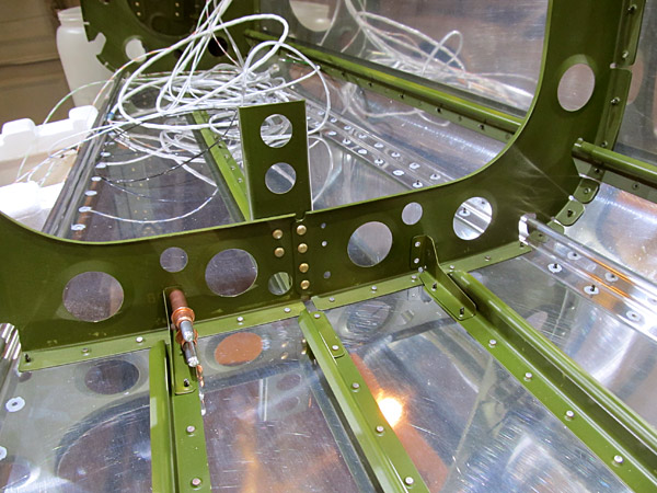
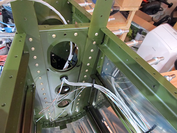
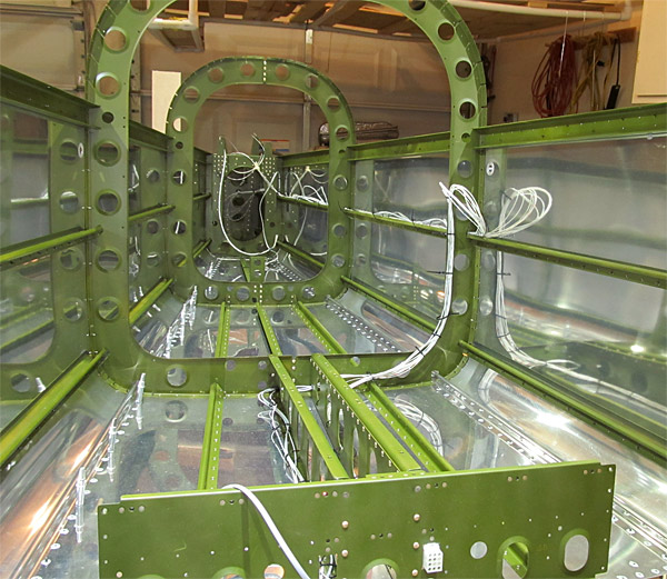
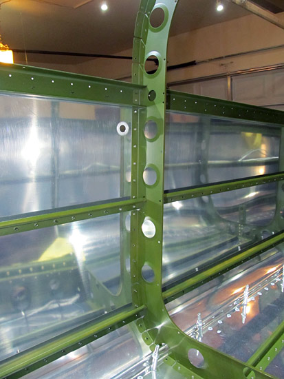
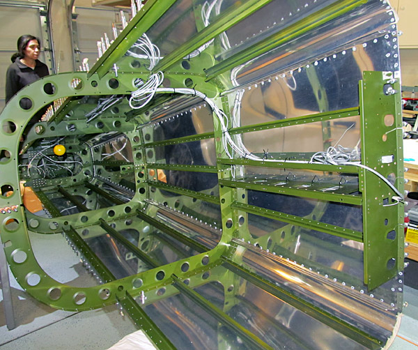
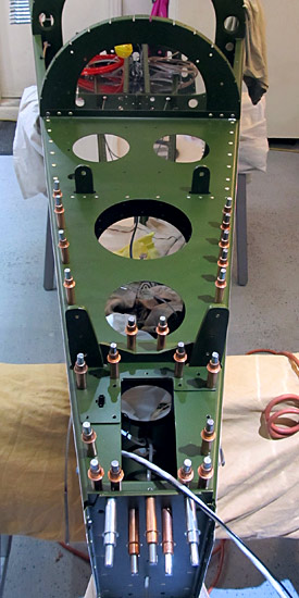
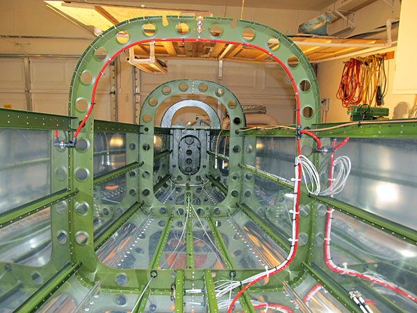
 The next task is to route the aft fuselage wiring harness (WH-00057) and the aft fuselage phone cable (WH-00059) along the bellcrank ribs (F-01429-L and F-01429-R) and into the channel of the J-stiffener (F-01486A-L) and through the notches of the aft fuselage bulkheads (F-01407 and F-01408).
|
 Basically page 10-21 shows what snap bushings go where along the wiring route but the main focus will be on pages 10-25 and 10-26 in the builder's manual. |
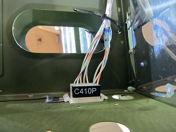 The larger molex connector end of the wiring harness (WH-00057) is to be labeled C410P. |
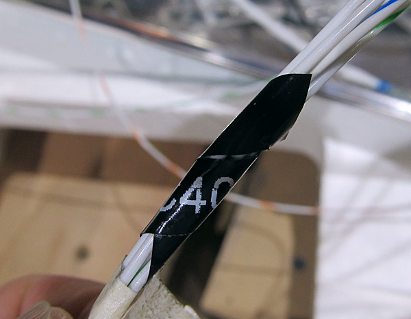 This is the smaller molex connector of the wiring harness (WH-00057) which is to be labled C409P. It is the molex that had the mis-crimped (ES-00047) pin connector. |
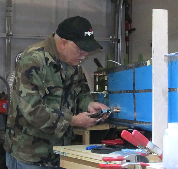
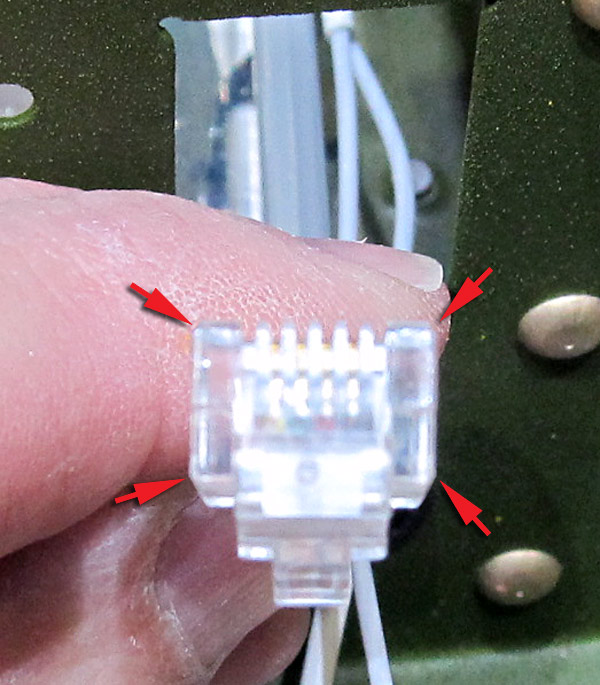 When threading the phone cable (WH-00059) jack through the holes in the bellcrank ribs (F-01429-R and F-01429-L) I had to lightly bevel the edges of the jack with 400 grit sandpaper in order to get it to pass through. It doesn't take much but it certainly made a difference. |
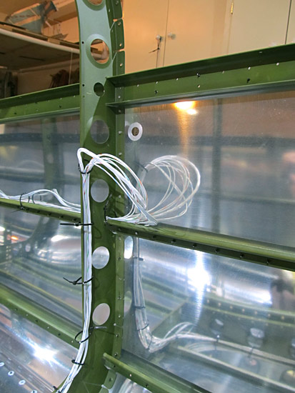
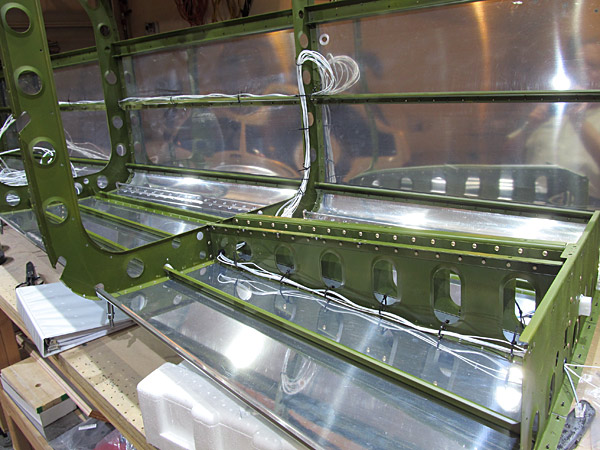 As you can see in this photograph the wires go across and up bulkhead (F-01407) and then aft through the notches and then sit in the channel of the J-stiffener (F-01486A-L). |
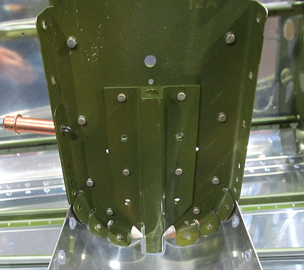
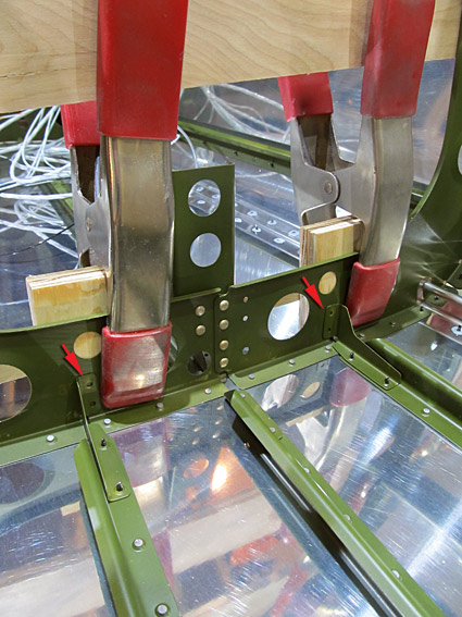 Now it's time to match drill the #30 holes of the vertical flanges of the (F-14147-L and F-14147-R) stiffener clips into the bulkhead (F-01408). |
 The holes are #30 match drilled. |
 After match drilling the #30 holes the stiffner clips (F-14147-L and F-14147-R) have to be removed and the holes deburred. |
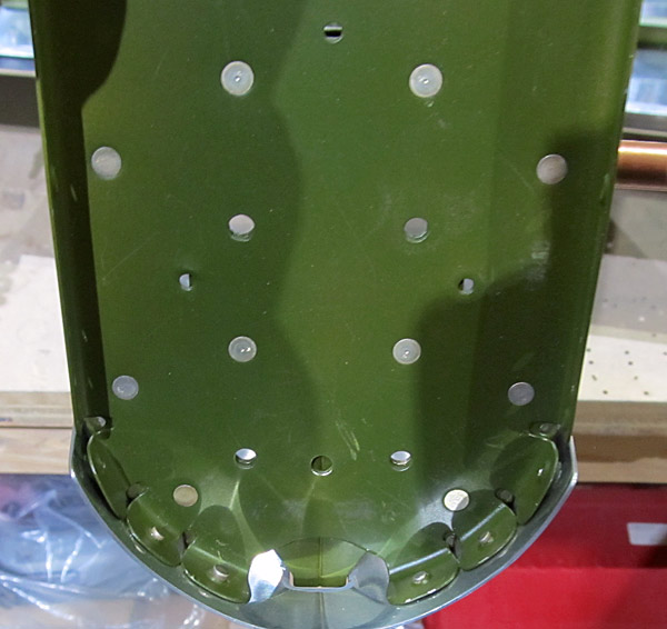
 There is a pilot hole that needs to be filled on the aft bottom skin (F-01479) and a AN426AD3-3 rivet is used to accomplish that. |
 Just a couple of "taps" and the rivet is set! |
|

|
 Next, the (F-01412) bulkheads are clecoed into position for riveting. |
 Remember the stiffener clips? I just got done riveting them in place. |
 Back to the aft bottom skin (F-01479) assembly. |
 Inside bulkhead (F-01412A). |
 Aft bulkhead (F-01412B). |
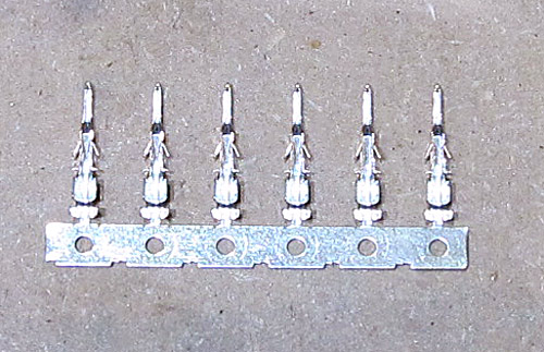 The (ES-00047) mini sub pins arrived so now I have to repair the mis-crimped pin on the blue and white wire I found on the wiring harness (WH-00057) that connects to the molex that is labled (C409P). After I did that I reinserted it into the molex and finished routing the wiring harness (WH-00057) and phone cable (WH-00059) through the aft fuselage assembly. |
 The cable ties have to be kept loose still. |
 Front to back.... The installation instructions are described on pages 10-25 and 10-26 of the builder's manual. |
 The stiffeners (F-01486A-R and F-01486B-R) are inserted into the slots in bulkheads (F-01407, F-01408). |
 There are two angle stiffeners (F-01473A) that get clecoed into position near where the inspection covers go on the right and left side of the aft fuselage.....I'm running out of clecos! |
 Here is what Van's said the correct order is: skin (F-01479) overlaps skin (F-01478), side skins (F-01473-R and F-01473-L) overlap skin (F-01479). |
 This is what it looks like on the right side. |
 This is what it looks like on the left side. |
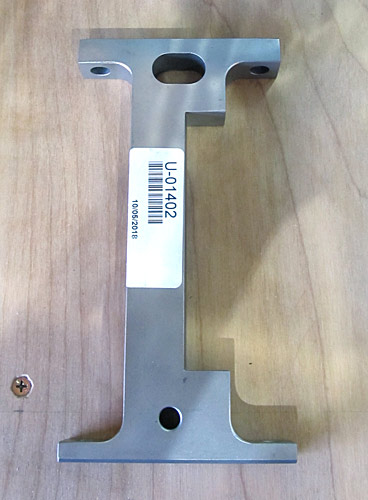 After we received the Quick Build fuselage kit I noticed that there were machining marks on the landing gear braces (U-01402). |
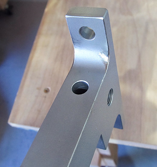 This photogragh shows the landing gear brace (U-01402) and the area I am talking about. This is after the marks have been "dressed out" using a small round file. |
 Meanwhile back at the aft fuselage side skins.... |
 We started out by riveting bulkheads (F-01410) and (F-01411) to the the bottom aft fuselage skin (F-01478) and lower aft fuselage "tailskid" (F-01479) skin using our 3x riveting gun and tungsten bucking bars to set AN426AD3-4 rivets. |
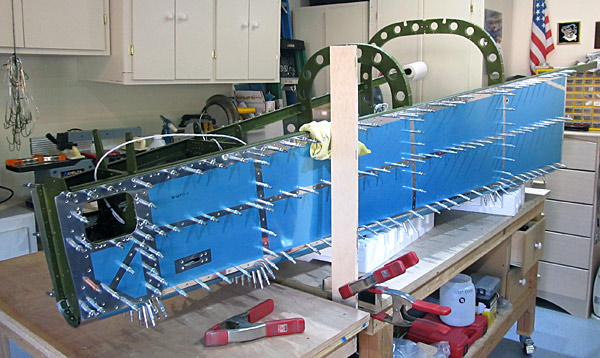
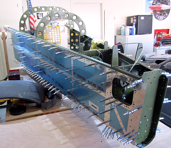
 Let the aft fuselage side skins (F-01473-L and F-01473-R) riveting begin! |
 According to step 1, page 29-03 of the builder's manual the ends of the landing gear brace (U-01402) does not get primed so I masked off the ends and prepared the brace for priming. |
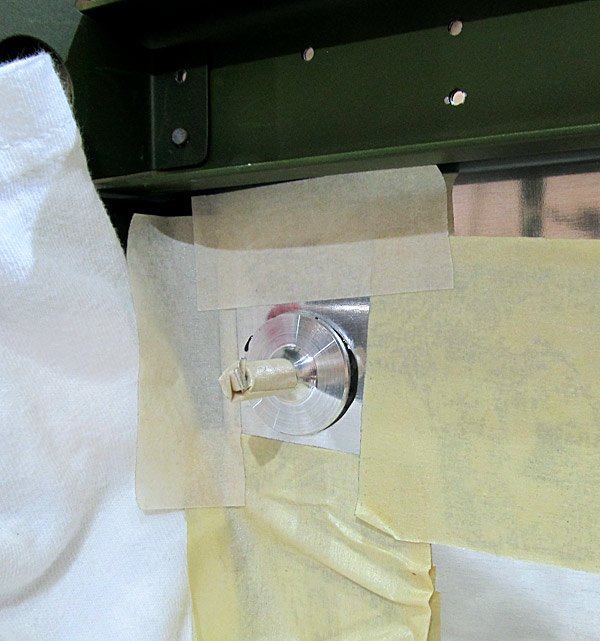
 As described earlier, the insides of the aft fuselage side skins had to be prepared in order to bond the static ports (Cleavelnad Aircraft Tools part # SPF-140) with tank sealant or RTV adhesive. |
 This is the left side. |
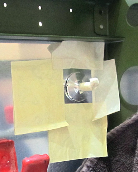
 I taped off around the area around where the static port will go so I don't get any extra "goo" spilled. |
 I put tape over the end of the static port too so tank sealant doesn't get inside. |
 I used the quick set tank sealant from Van's aircraft to bond the static ports to the left and right aft fuselage side skins. |
 Right side set into place. |
 Left side set into place. |
 Polished static port! |
 Let the sealant cure for a few days. |
 It's nice because this eliminates the short 1/8" tubing stub that you have to use in the standard static port install and can go directly to 1/4" tubing. |
 Back to riveting the left and right side skins (F-01473-L and F-01473-R)! |
 Here's what it looks like on the inside. |
|
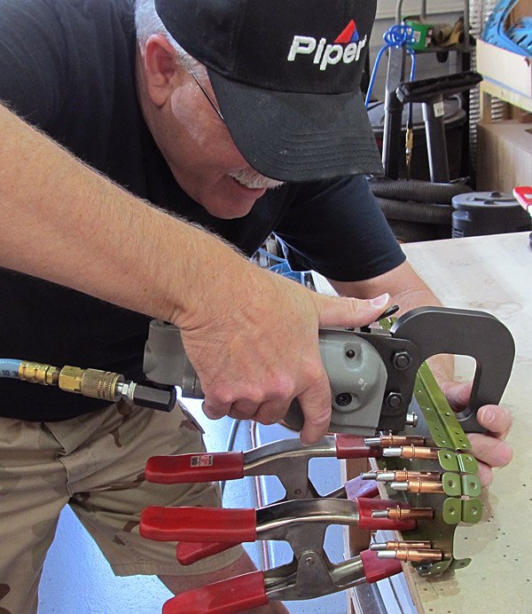
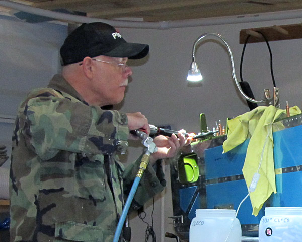
 Here we are, my wife handles the rivet gun and I hold the bucking bar. |
 I "dressed out" the machining marks in the right side landing gear brace (U-01402) and masked off the ends and prepared the part for priming. |
 I primed the landing gear brace (U-01402) with DupliColor self etching green primer (DAP 1690) just like I did for the left landing gear brace. |
 I am back to my side project and am starting the debur process on the aft baggage bin bulkhead (F-01406C). |
 All of the #30 and #40 holes have been final sized using the appropriate reemers, the edges have been deburred, and now it is time to dimple. |
 I dimpled all of the #40 holes in the flanges of the bulkhead (F-01406C) using our hand squeezer. |
 The #40 nutplate attach holes and the #30 holes have been dimpled using our DRDT2, the surfaces have been scuffed with ultrafine ScotchBrite pads, and everything wiped down with acetone in preparation for priming. |
 I primed the aft baggage bin bulkhead (F-01406C) with DupliColor self etching green primer (DAP 1690). |
 Now it is time to work on the aft baggage bin right side bulkhead (F-01406A-R). |
 Take off the blue vinyl! |
 Shiny! |
 I scuffed the surfaces of the aft baggage bin bulkhead (F-01406A-R) with ScotchBrite ultrafine pads before the dimpling process begins. |
 I dimpled all of the #40 holes (except as noted in figure 1, page 30-02) using our hand squeezer. |
|
|
 The #40 nutplate holes get dimpled flush on the aft side of bulkhead (F-01406A-R) as indicated in figure 1, page 30-02 of the builder's manual. I did that with our DRDT2. |
 I primed the aft side of the aft baggage bin bulkhead (F-01406A-R) with DupliColor self etching green primer (DAP 1690.) |
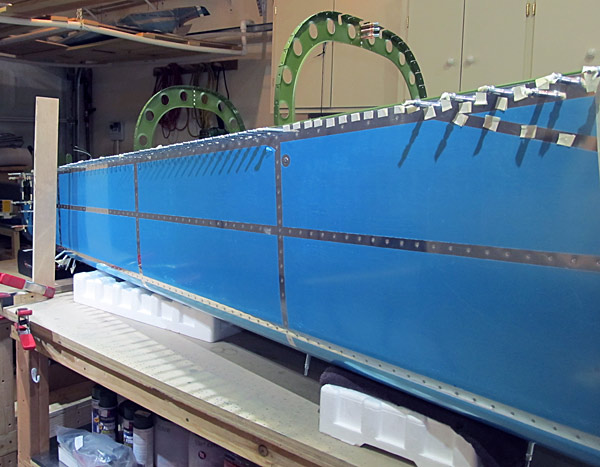 Riveting the aft fuselage side skins (F-01473-L and F-01473-R) to the aft fuselage assembly continues using the rivet callouts as provided in figure 1, on page 10-19 of the builder's manual. |
|
|
 Now it's time to set the bottom row of rivets. |
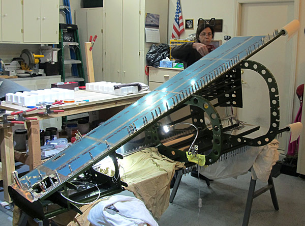 Another view of our setup. My wife will be handling the rivet gun and I will be doing the bucking. |
 A view of the "skidplate" area. |
 Here we go! |
 Nice! |
|
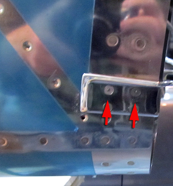
 Now we move on to the next step which is to rivet the right and left rudder stops (F-14113-L and F-14113-R) into place. Sounds simple right? All you have to do is rivet eight AN426AD4-6 and you're done. Well, it wasn't so simple for us; those are pretty big rivets and the work space is very tight. We had to drill out three rivets on the left side here. The angle of the rudder stop interferes with our mushroon set on the top two rivets and we can't get the set to sit flush to the rudder stop (that is why we drilled the rivet out). |
 I am waiting on the parts to arrive. |
 There are twelve K1000-06 nutplates to be installed (six on each side) of the aft fuselage assembly. |
 The rest of the rivets to attach the nutplates are AN426AD3-4 rivets which we set using the 3x rivet gun and a tungsten bucking bar. |
 We are waiting to hear fron Van's Aircraft to see if we can substitute two CR3212-4-3 CherryMax rivets for the two AN426AD4-6 rivets called for in the plans because the space is pretty tight in the angle portion of the rudder stops (F-14113-L and F-14113-R) and it would be easier to use a blind rivet here. |
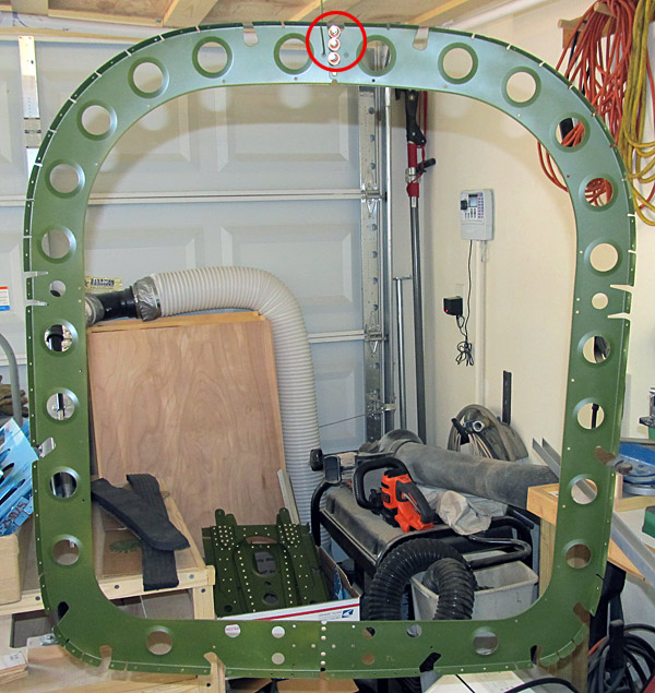
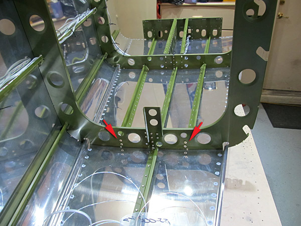
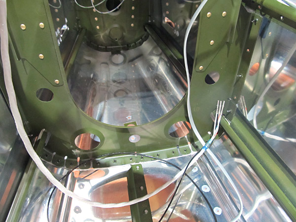
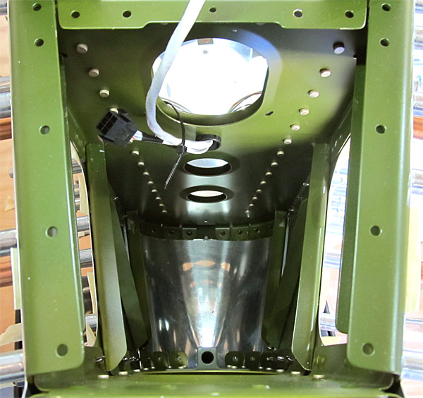
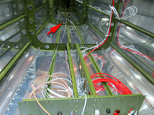
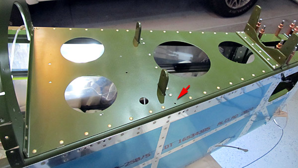
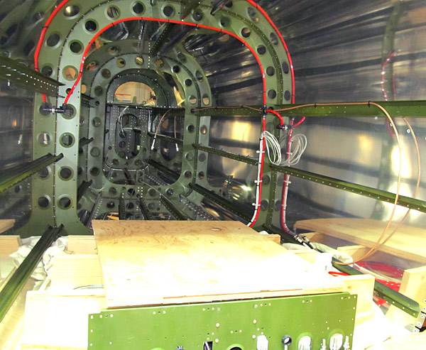
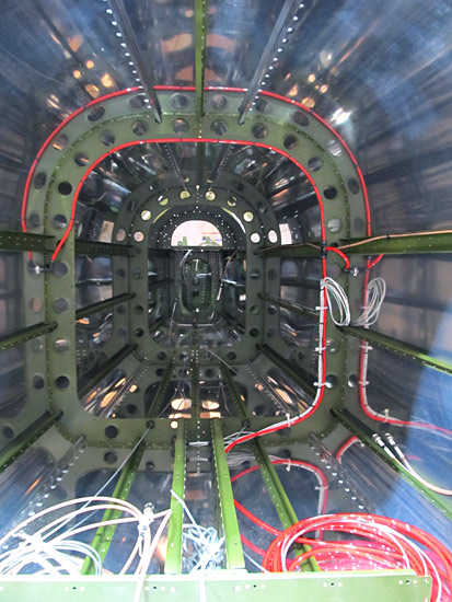
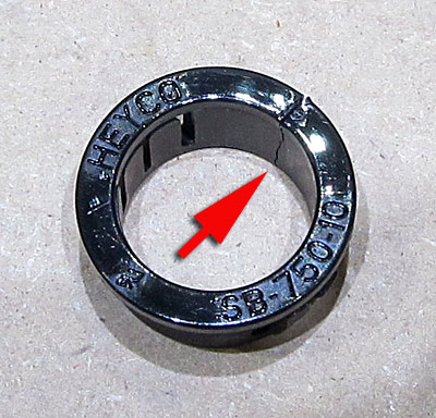 Snap bushings were installed into the aft fuselage assembly using figure 1, page 10-21 of the builder's manual as a reference so that the orientation of the bushings were correct. |
 You can see the bushings in this photograph at the bottoms of the bulkheads, this is where the rudder cable will be routed through. |
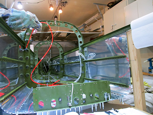
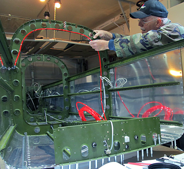
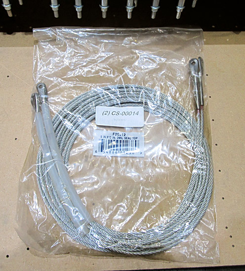 The rudder cable is to be routed through the bulkheads starting from the aft end of the fuselage assembly and working forward. This is part number (CS-00014). |
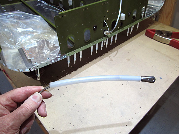 The rudder cables (CS-00014) have plastic sleeves on one end and no plastic sleeve on the other end. The plastic sleeve is to be located at the forward end of the airplane. |
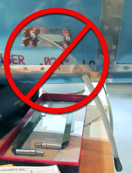 Don't do this! |
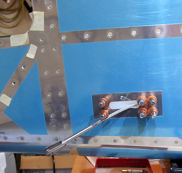 This is the correct way to route the rudder cable (CS-00014). |
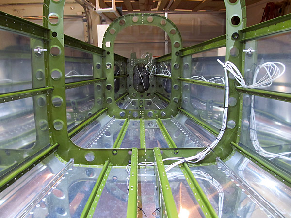
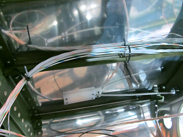
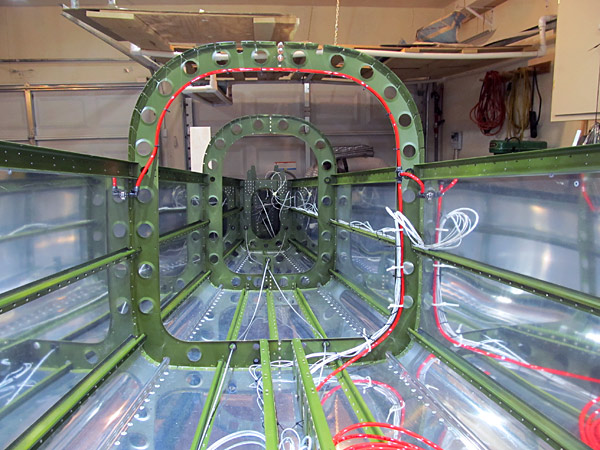
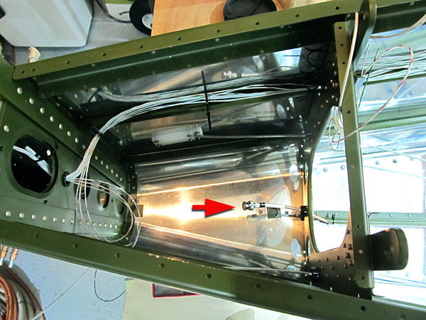
 This shows the cables as they are routed through the snap bushings in the bulkheads. |
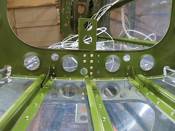
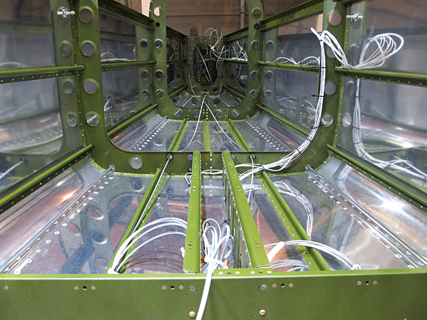
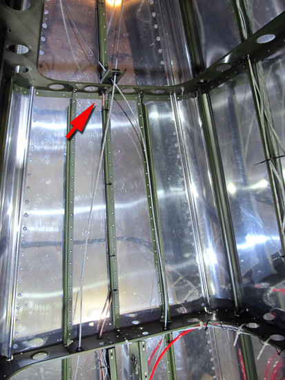 Here is an overhead shot where you can see the rudder cables crossing near bulkhead (F-01408) to opposite sides in the aft fuselage assembly. |
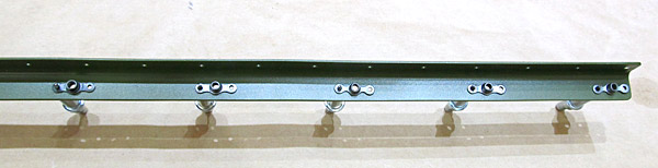
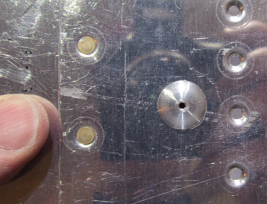
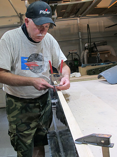
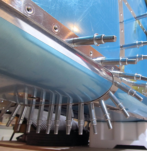
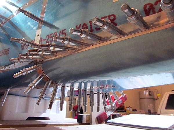
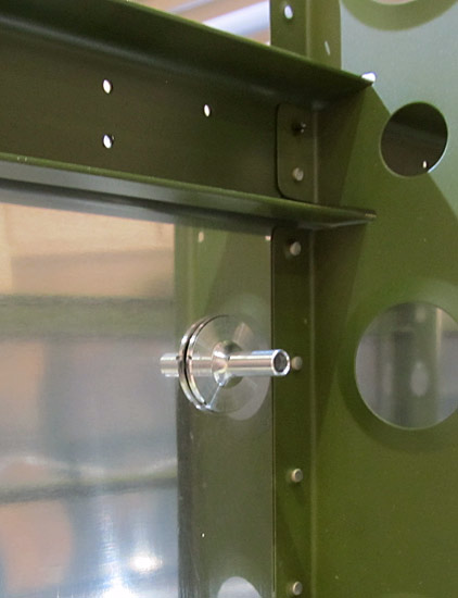
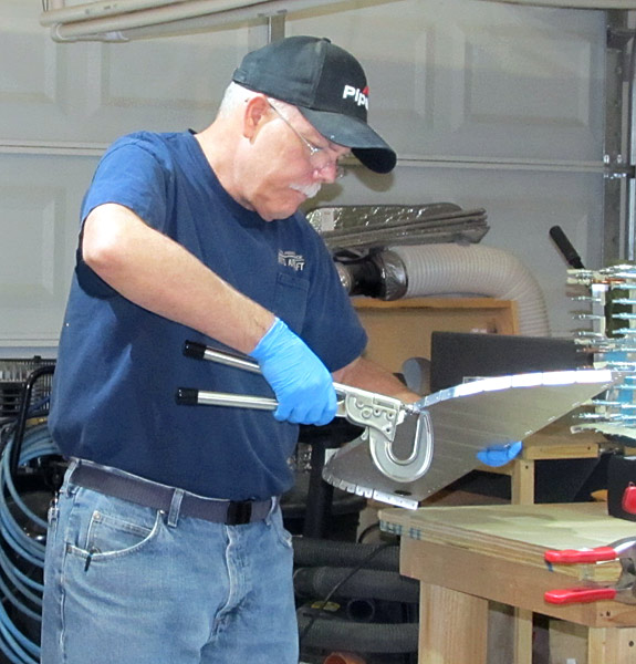
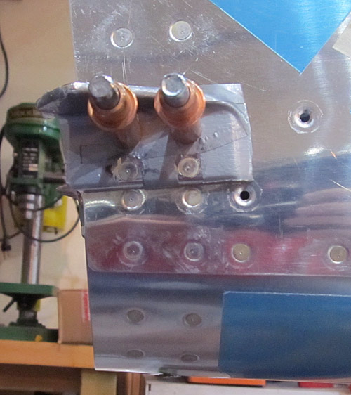
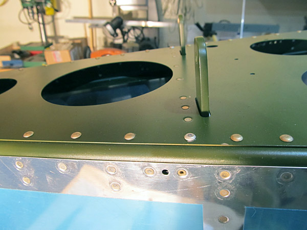
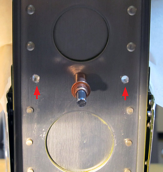
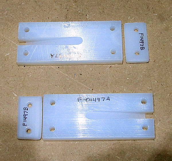 The next step is to prepare the rudder cable guides (F-01497A and F-01497B) before they are riveted into place on the aft fuselage side skins. |
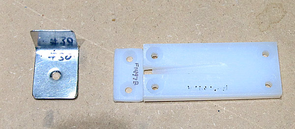 The #30 holes in the rudder cable guides (F-01497A and F-01497B) were machine countersunk to accept a dimpled skin. |
 I just put a #30 pilot countersink end into my debur tool and did the countersinking by hand. |
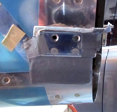
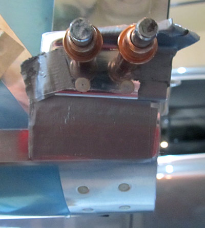
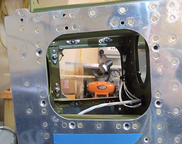
 Here is what it looks like (from the inside) when the rudder cable guides (F-01497A and F-01497B) are clecoed in place. |
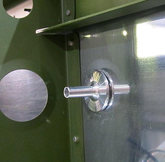
 I riveted the rudder cable guides (F-01497A and F-01497B) using our CherryMax G-27 hand rivet gun to set AACQ4-4 blind rivets which are backed up with NAS1149FN416P washers. |
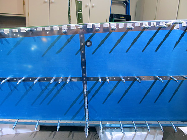
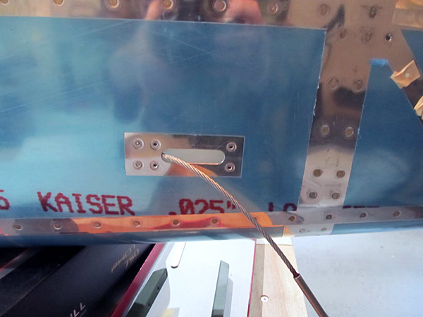 This is what it looks like on the outside... |
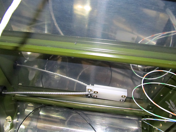 This is what it looks like on the inside. |
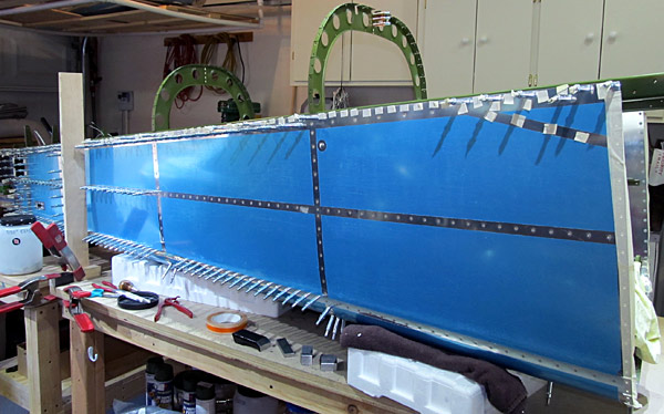
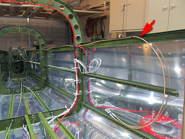
 Time to install the left and right static lines. |
 The lines are routed the same way as the plans state but use fewer parts and is just nicer in appearance and easier to work with. |
 Static lines installed! |
 The extra static line is coiled and stowed behind bulkhead (F-01406B). |
 The UAT cable (WH-00014) is routed forward through bulkheads (F-01410, F-01408, and F-01407) and the associated snap bushings using figure 1, on page 10-23 of the builder's manual as a reference. |
 The ELT cable (WH-00015) was routed from the aft section of the fuselage through bulkhead (F-01408,) through the snap bushings to bulkhead (F-01407). |
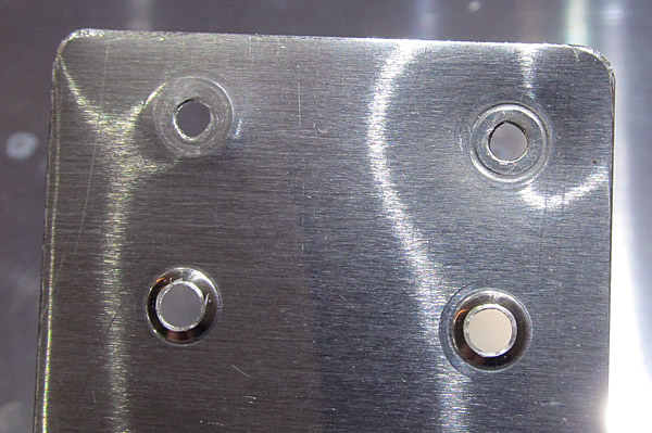
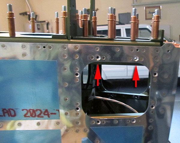
 In order to have the inspection covers (F-14112) sit flush to the aft fuselage section the #40 holes in the nutplates (K1100-06) that will be attached to the inspection covers holes in the left and right aft fuselage skins (F-01473-L and F-01473-R) have to be dimpled. |
 *The top two nutplates (K1100-06) on each side of the skins where the inspection cover sits do not need to be dimpled because later these will be machine countersunk due to the fact that they are "nested" within the left and right longerons (F-01418B-L and F-01418B-R). |
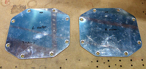 I dimpled the holes in the inspection covers to accept a number six screw. |
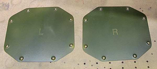 To further avoid confusing the left and right inspection covers, I also primed the insides and labeled them. The primer used is Tempo A702 green primer. |
 The remaining rivets of the left and right rudder stops (F-14113-L and F-14113-R) were installed. |
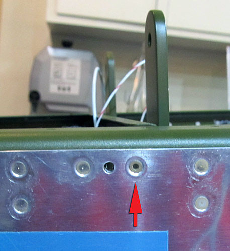
 The K1100-06 nutplates were installed in the left and right aft fuselage skins. |
 This is what it looks like on the outside. |
 The top two holes were machine countersunk to receive a number six screw in a dimpled inspection cover skin. |
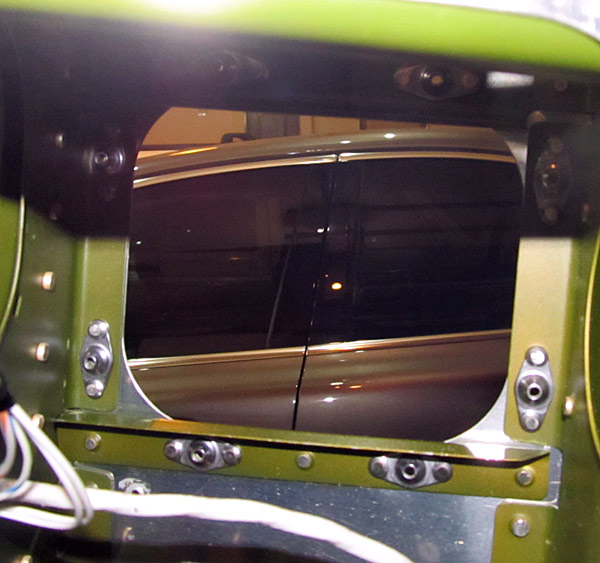
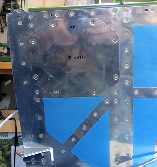 This is what it ends up looking like when the inspection cover (F-14112) is screwed into place. |
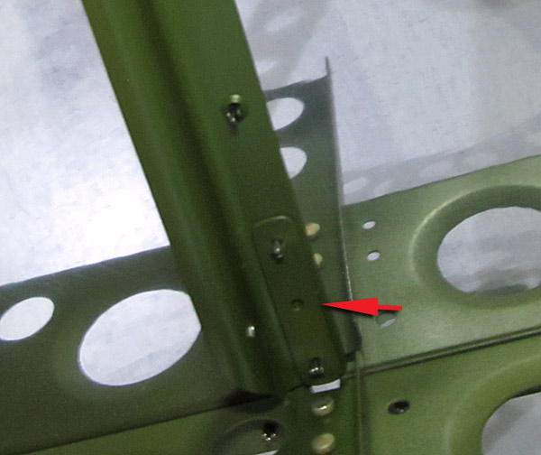
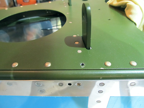
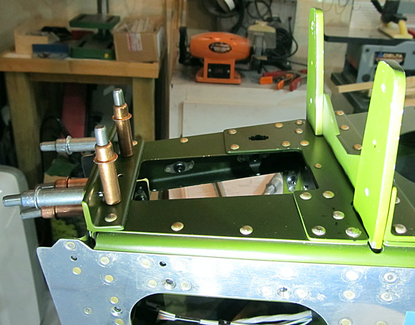
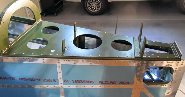
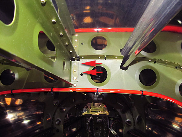
 The aft deck (F-01414), the deck angle (F-01412C),the horizontal stabilizer attach bar (F-01411D), and the bulkhead (F-01409) were clecoed to the aft fuselage assembly. |
 The horizontal stabilizer attach bar support angle (F-01411D) and the (F-01411C) attach bar were clamped together so that the two #30 holes could be match drilled into the horizontal stabilizer attach bar support angle (F-01411D) as shown in figure 3, page 10-27 of the builder's manual. |
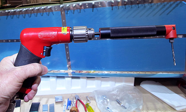 Space is tight here with the clecos holding everything in place so I elected to use the 90° drill attachment to match drill these two #30 holes. |
 Let the match drilling begin! |
 After match drilling the #30 holes, the horizontal stabilizer attach bar support angle (F-01411D) was removed and all the newly drilled holes were deburred. |
 It's now time to start riveting the aft deck (F-01414) to the aft fuselage assembly.The rivet callouts are shown in figure 2, page 10-27 of the builder's manual. |
 While I was waiting for my rivet partner (wifey) I started to peel off the blue vinyl from the bulkhead (F-01406A-L). |
 Let the deburring and work begin! |
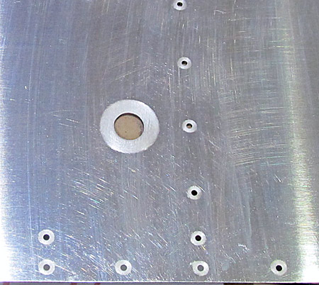
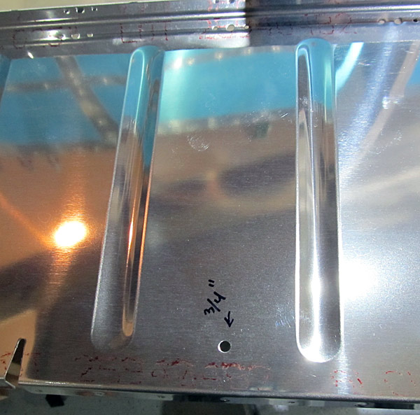 The first step is to enlarge the .191" hole to 3/4" in the bulkhead (F-01406A-L) using a step drill. |
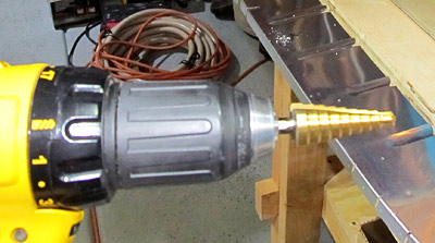 This is what I used to enlarge the hole. |
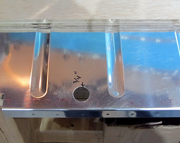 Here is the hole after it has been enlarged. |
 Back to riveting the aft deck (F-01414) to the aft fuselage assembly. |
 Spaces are tight in this area too but if you have a 3" and 1.5" yoke, you can set a lot of the rivets with a hand squeezer. |
 Back to work on the side projects.... |
 The #40 holes in the flanges of the baggage bin bulkhead were dimpled with our hand squeezer. |
 I used masking tape to remind me not to dimple this tab. |
 I washed the baggage bin bulkhead (F-01406A-L) with acetone and then masked the bulkhead off just like I did for the right side. I plan to prime the aft side of the bulkhead with green primer but leave the forward side bare for now and prime it later when I prime and topcoat the inside of the cockpit and fuselage. |
 I primed the aft side of the baggage bin bulkhead (F-01406A-L) with Duplicolor self etching green primer (DAP 1690). |
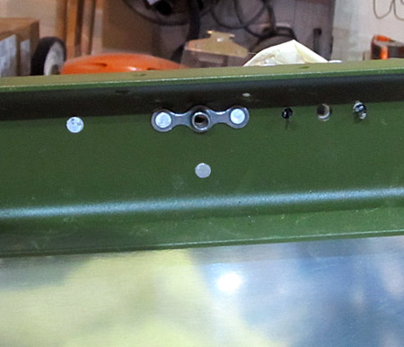
 We got word back from Van's Aircraft that it would be okay to replace the aft-most rivets that attach the left and right angle stiffeners (F-01473A) to the left and right aft fuselage skins with MK-319-BS blind rivets so that is what we did. |
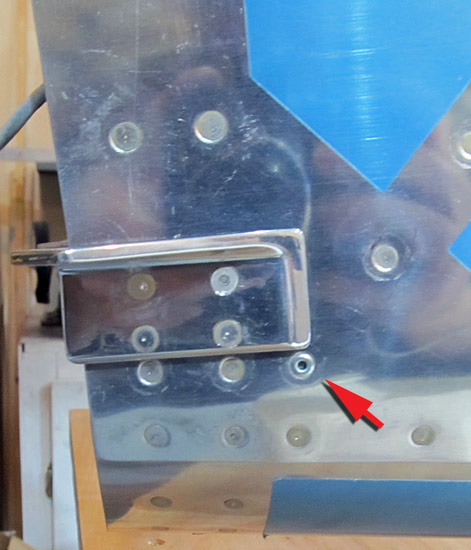
 This is another tight spot that we got permission from Van's Aircraft to substitute a CherryMax CR3213-4-2 for the AN470AD4-4 which is near bulkhead (F-01410). |
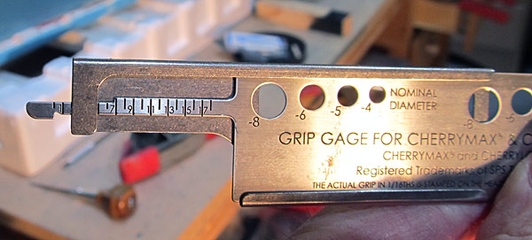 We determined the length of what CherryMax rivet to use by measuring the depth with our CherryMax Grip gauge. |
 We set the rivet with our G-27 CherryMax rivet gun. |
 Here's another view. |
 I set the two corner AN470AD4-7 rivets in the corners of the deck angle (F-01412C) with a hand squeezer equipped with a 3" yoke. |
 I was able to set these middle rivets that are between bulkhead (F-01411) and bulkhead (F-01412A) using the hand squeezer equipped with the 1.5" yoke. |
 Setting these seven rivets finishes up securing the aft deck (F-01414) to the aft fuselage assembly. |
 TahDah!....aft deck secured! |
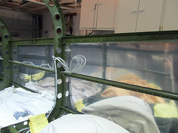
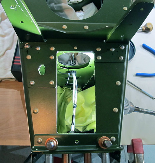
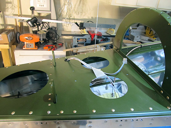 Next the wires have to be finish routed through the aft deck (F-01414) as per figure 3, page 10-27 of the builder's manual. |
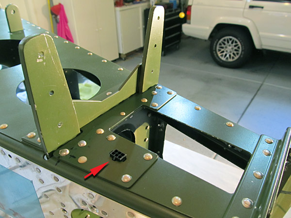 C409P is then set into position in the aft deck (F-01414). |
 The tie wraps were tightened and the ends clipped for a neat appearance. |
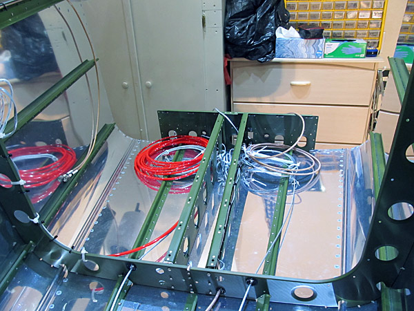 The loose ends of all of the cables were coiled and stowed behind bulkhead (F-01406B) |
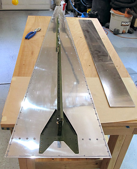 I mocked up the aft top skin (F-01475 with the upper aft fuselage rib (F-14131), the J-stiffener (F-01486F), and the skin doubler (F-01475A) to insure all fit well together. |
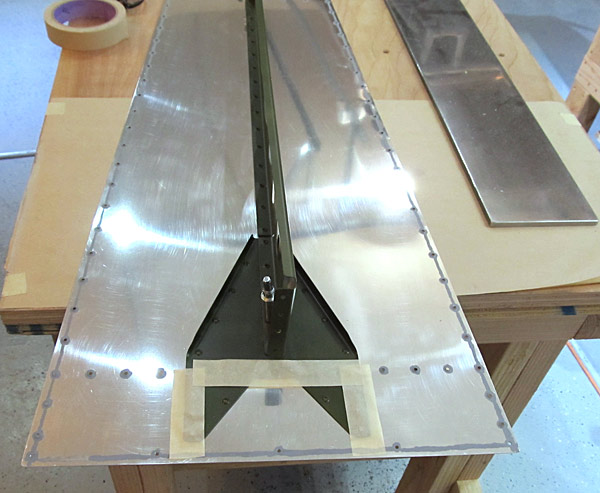 There are several holes that do not get riveted at this time so I put masking tape over them so as not to accidentally rivet them. |
 I started out by riveting the J-stiffener (F-01486F) to the aft fuselage top skin (F-01475) setting AN426AD3-3.5 rivets set with the normal length back rivet set in our 3x rivet gun. |
 The next piece to be riveted into place is the upper aft rib (F-14131) but in order to clear the flanges of the rib it was necessary to use a 12" extension back rivet set in our 3x rivet gun. |
 Here it is all together. |
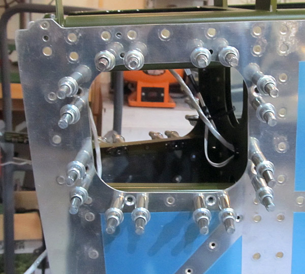
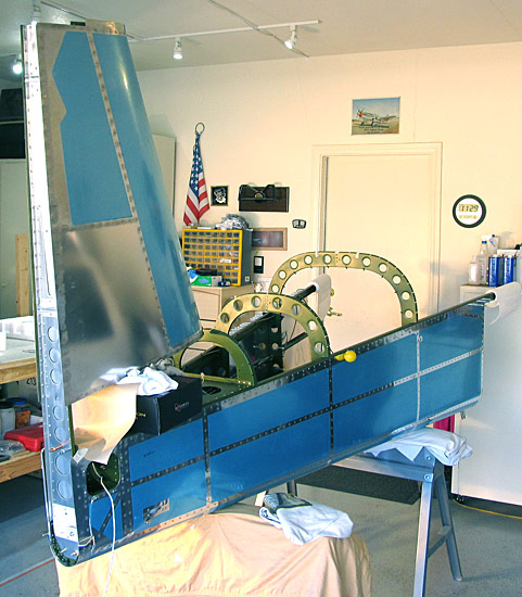 The vertical stabilizer needs to be temporarily mounted to the aft fusealage assembly as described in step 1, page 10-28 of the builder's manual. |
 Here we are final drilling those two #12 holes into the bulkhead (F-01412) and the deck angle (F-01412C). |
 These are the final #12 holes. They were deburred after drilling. |
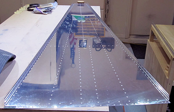
 The left aft fuselage top skin (F-01474-L) was clecoed onto the aft fuselage assembly. |
 There are several holes that do not get riveted at this time so we used masking tape to identify them so that we didn't inadvertently rivet them. |
 Finished riveting the left top skin (F-01474-L). The taped off areas are where the plans indicate the holes should not be riveted. Some of the holes will be riveted later in either the fuselage joining or when the top skin will be put into place. |
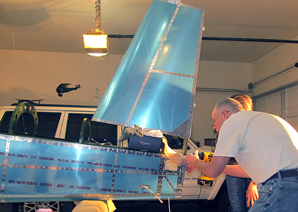
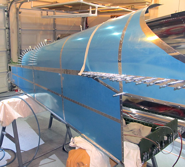
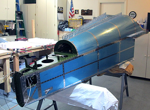
 The right top skin (F-01474-R) was clecoed onto the aft fuselage assembly. |
 Here we are riveting the right top skin (F-01474-R) to the aft fuselage assembly. |
 Just like we did on the left side, we did the same on the right side. |
 Finished riveting the right top skin (F-01474-R) to the aft fuselage assembly. |
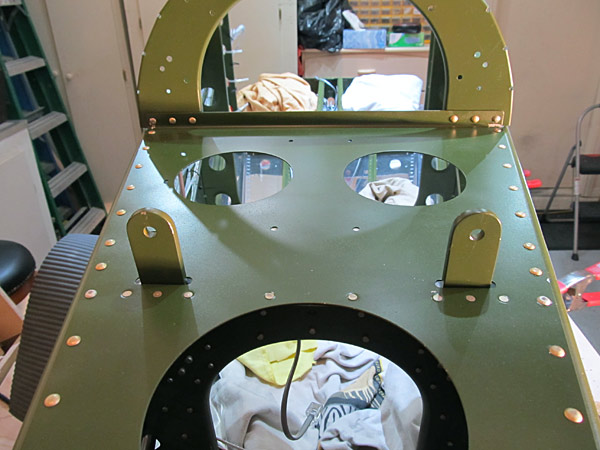
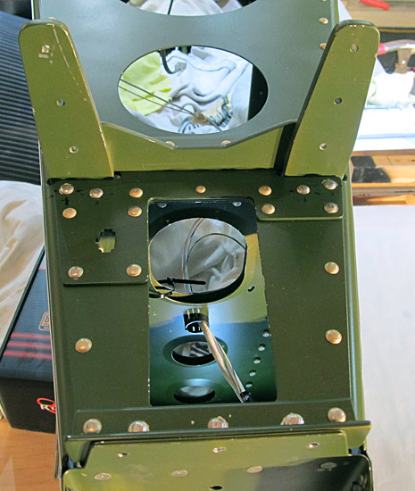
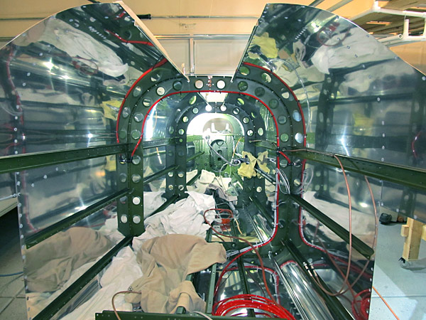 Here is what it looks like on the inside, I put old t-shirts on the bottom skin just in case something slipped....didn't want to damage all that pretty metal! |
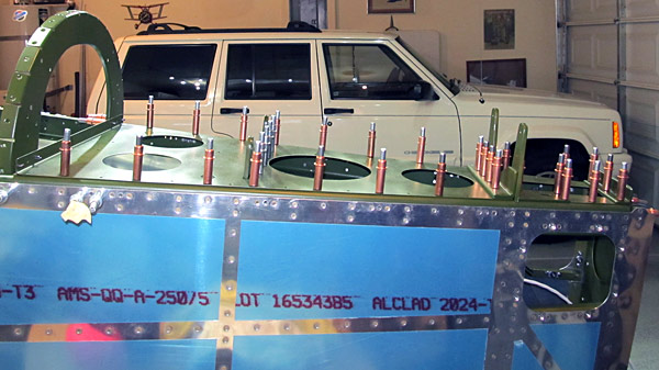
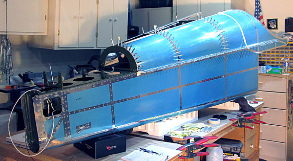
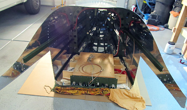
 The top skin assembly (F-01475) was clecoed onto the aft fuselage assembly. |
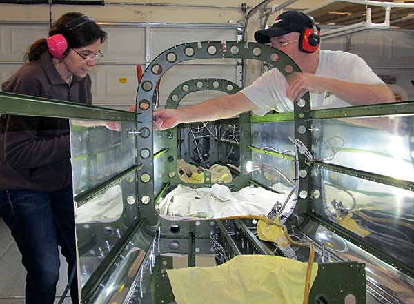
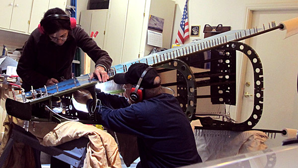
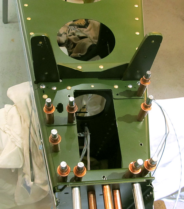
 I built some temporary supports so that I could bridge my weight over the top of the inner bulkheads, I didn't want to get anything bent inside because no matter how you look at it , someone has to crawl inside of the aft fuselage to do the bucking part of the rivet process. |
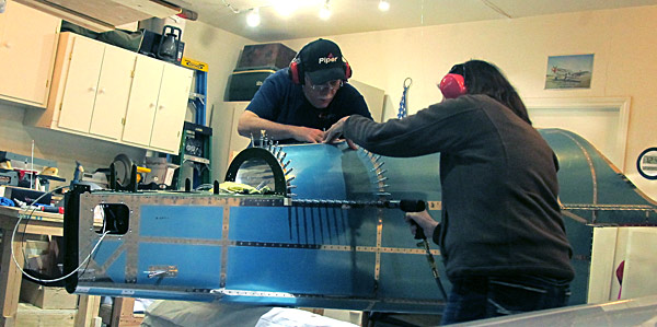
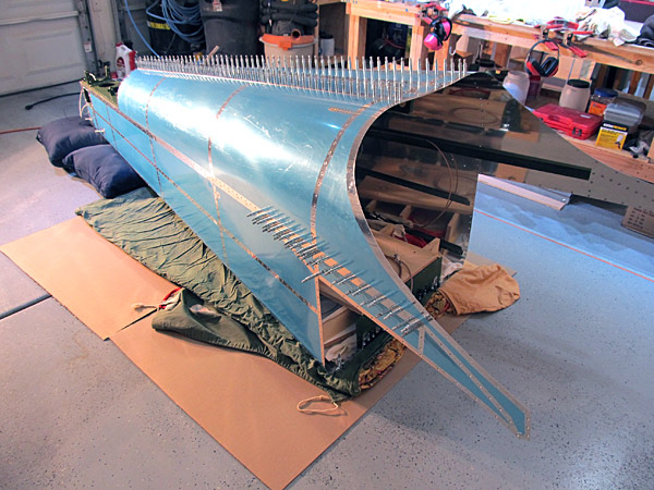 We set the aft fuselage assembly on the floor to make the fuselage stable and much easier for me to crawl inside to handle the bucking bars while my wife handled the 3x rivet gun equipped with a swivel mushroom set on the outside. |
 Going into the doghouse now! |
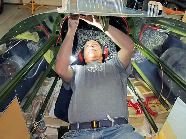 It helps to have some pillows all over, got to make it at least a little bit comfortable! |
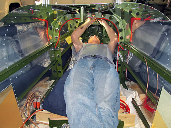 The "bridge cradle" worked well. |
 Getting deep within the fuselage now. |
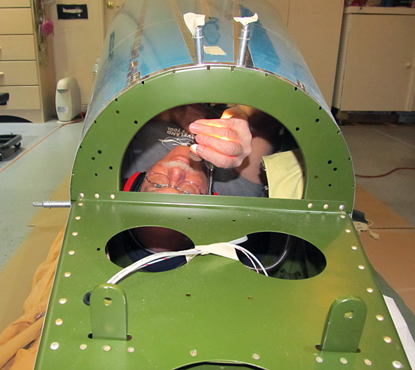 It really is tight back here! |
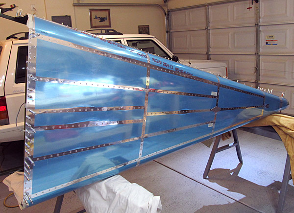
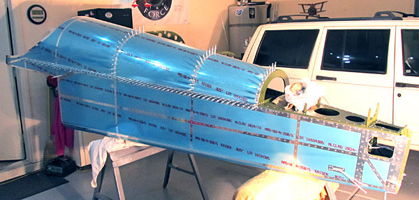
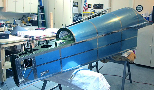
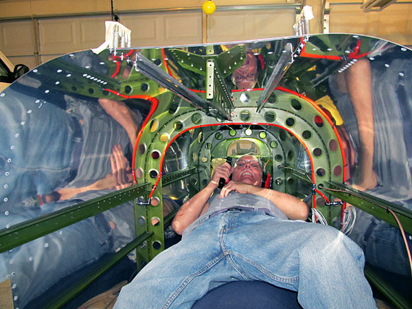
 The top skin is rivet onto the aft fuselage! |
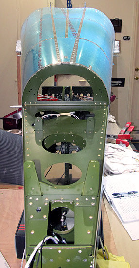 Nice. |
 The toughest part about riveting the top skin (F-01475) (for me) was at the intersection of bulkhead (F-01407) and the top aft rib (F-14131).There are three AN470AD4-4 rivets called out to join the two pieces. I was able to set the bottommost solid rivet with our pneumatic squeezer but had to substitute the top two rivets with CherryMax CR3213-4-2 rivets due to the tight space. The CherryMax rivets are extremely strong and according to the EAA can be directly substituted for solid rivets of the same size. |
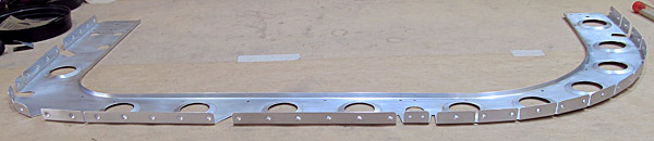
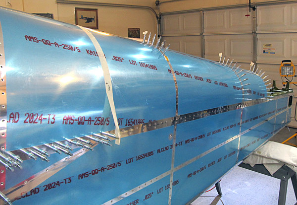
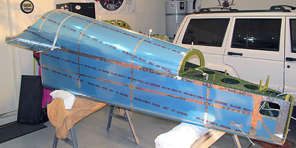
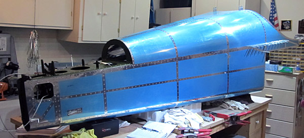
 Well, there it is, all of the skins have been riveted on and the empennage kit is completed, now the next thing to do is transport it to our hangar to be joined to the front half. |
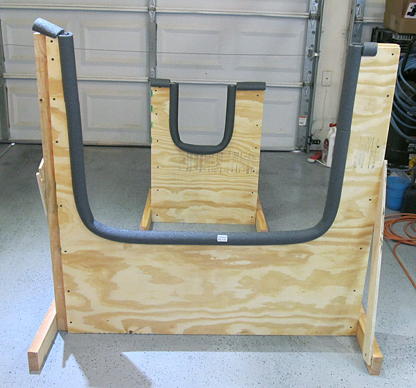 I made some cradles so that we can transport the empennage to the airport. |