Empennage- Elevators and Trim Tab

I ordered the Empennage/Tailcone Kit to build first in the RV14A project. Van's Aircraft does not provide a "QuickBuild" option for the empennage.

RV14A Empennage Kit
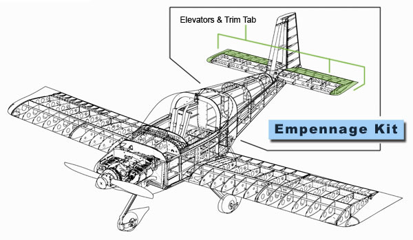
Basically, the empennage kit includes everything aft of the canopy and is about half of the total fuselage.

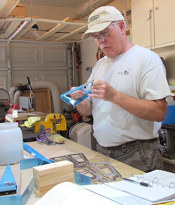
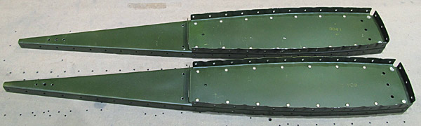
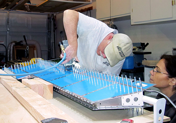
The forth item to work on according to the builder's plans is the Elevators and Trim Tab.
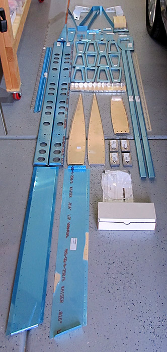
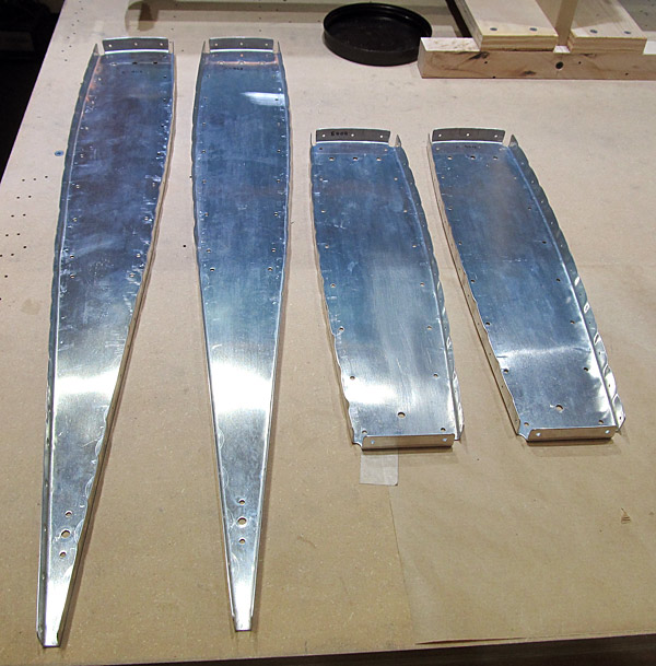
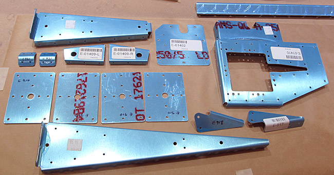
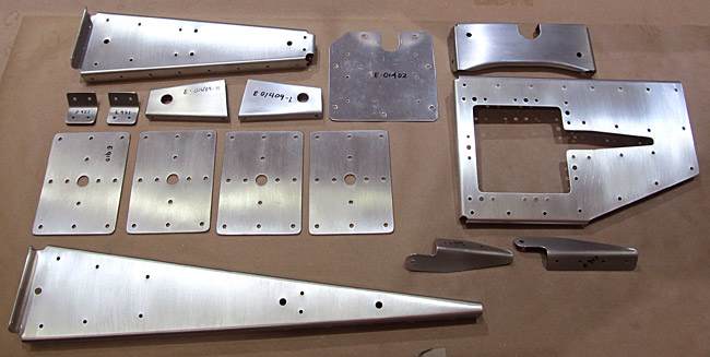
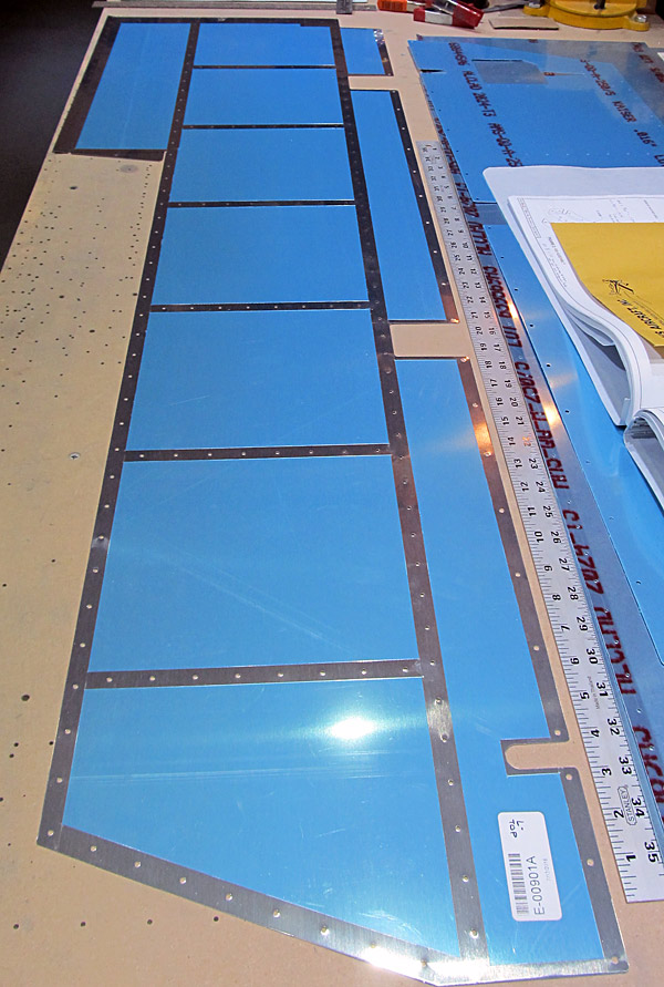
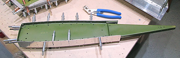
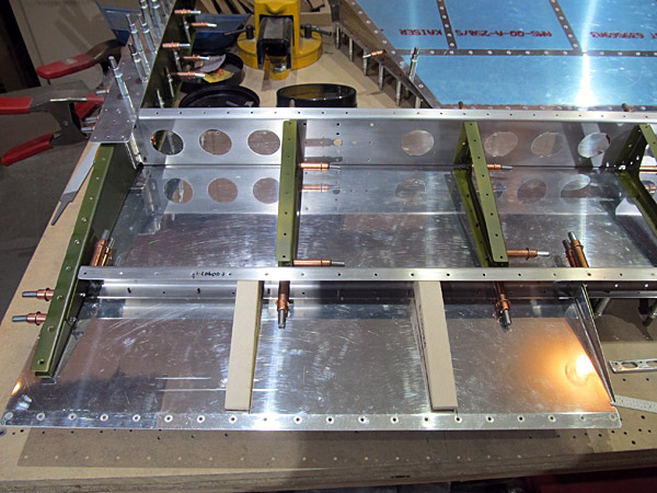
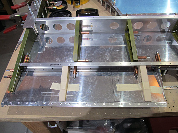
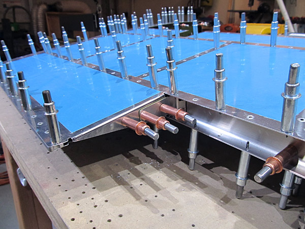
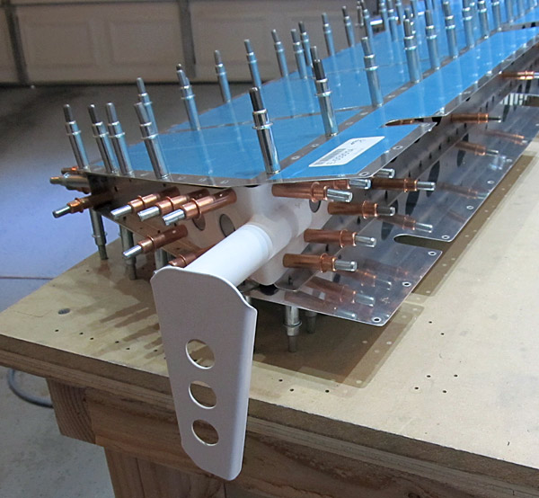
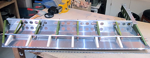
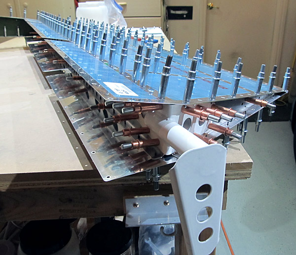
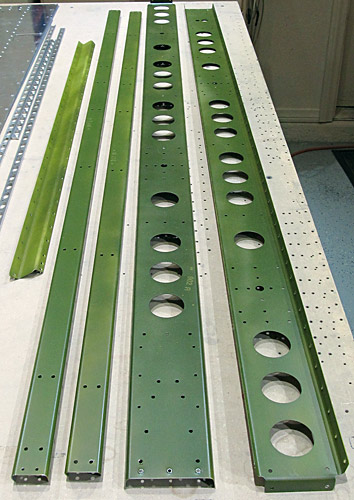
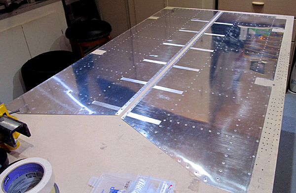
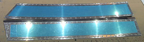
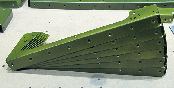
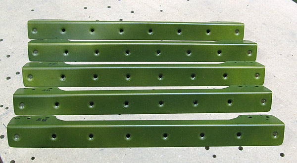
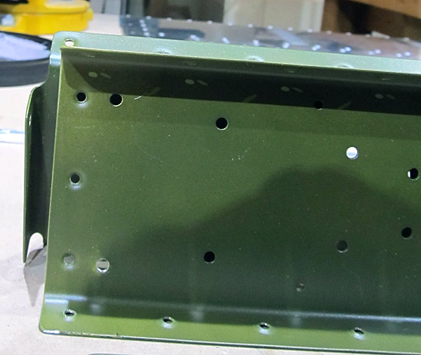
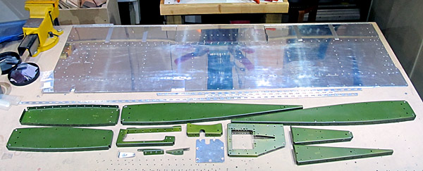
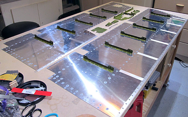
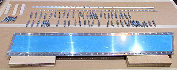
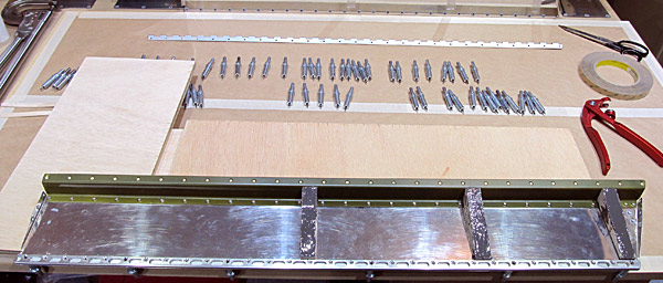
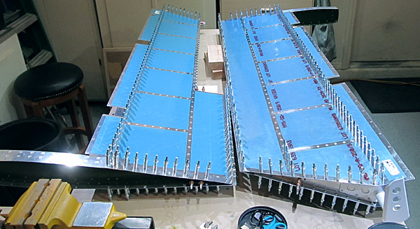
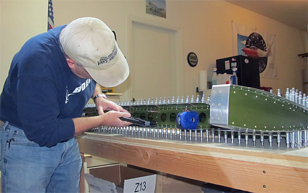
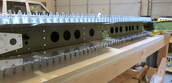
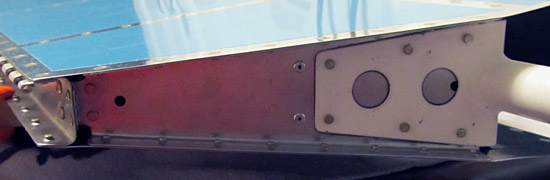
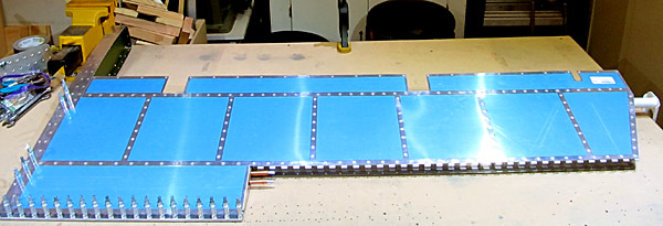
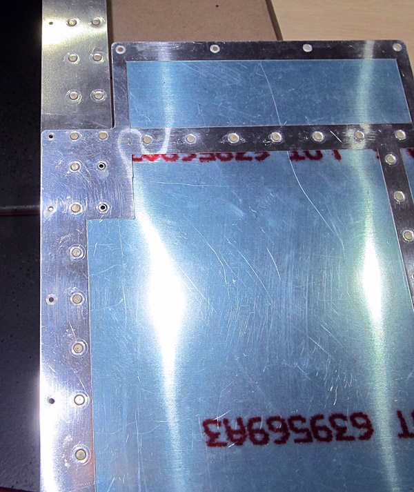
I pulled the individual parts from the inventory that are needed to assemble the left and right elevators and trim tab section.

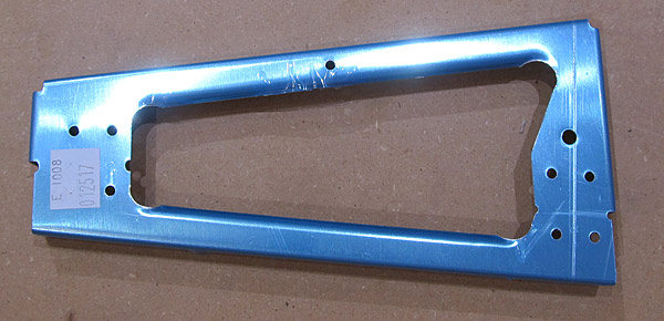
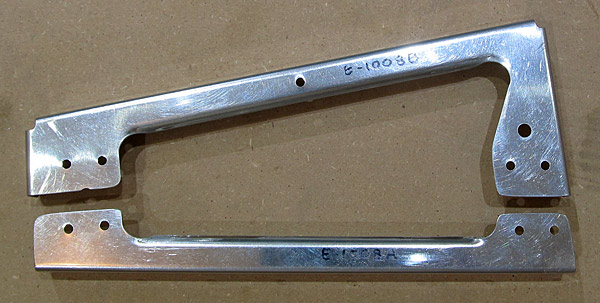
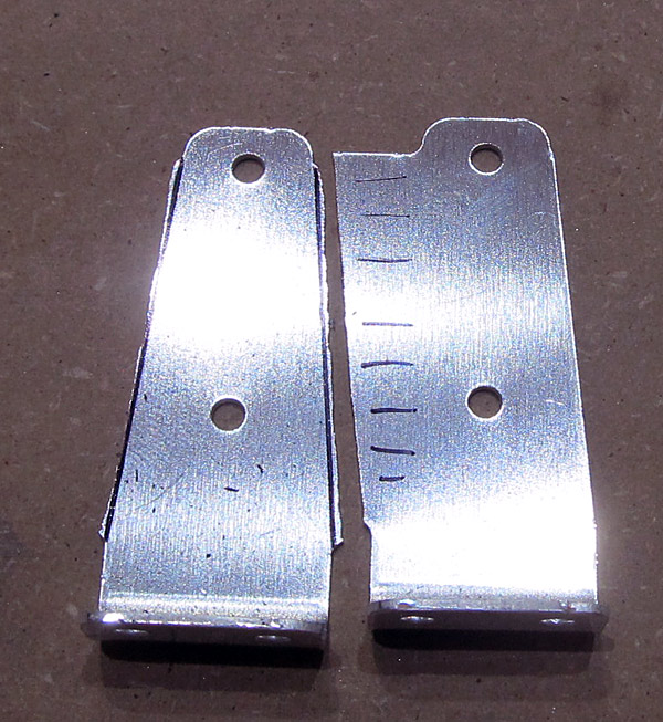
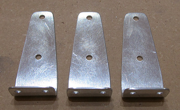
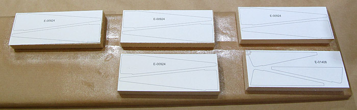
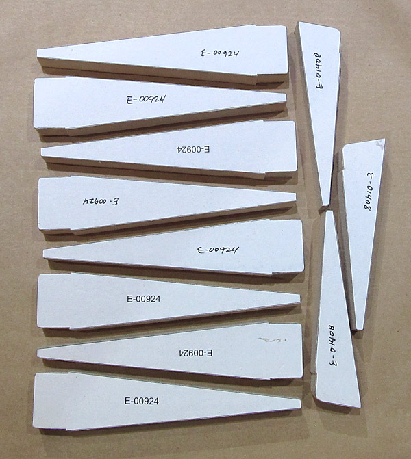
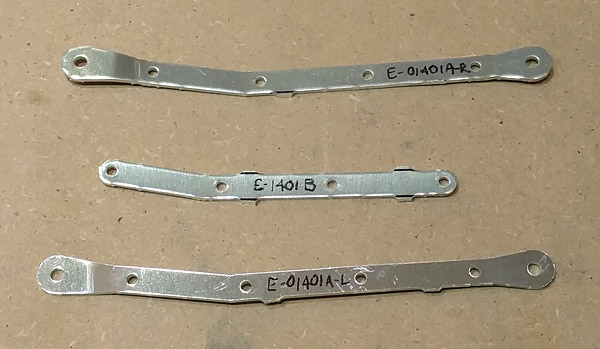
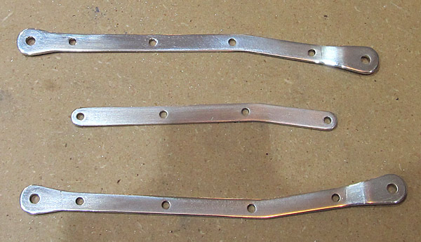
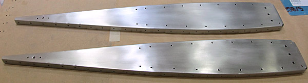
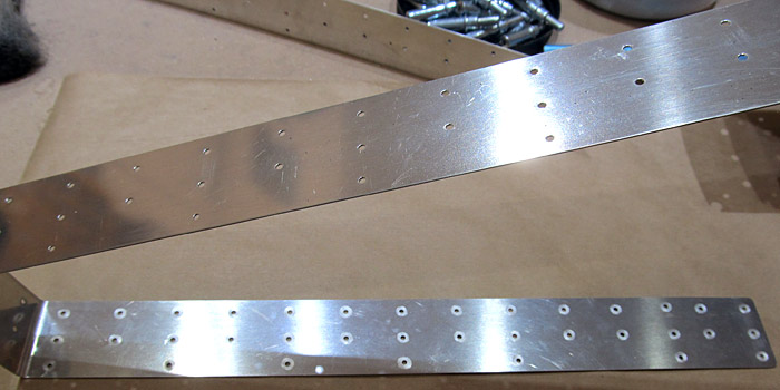
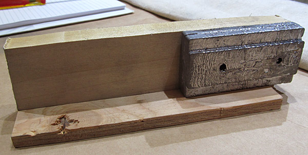
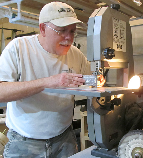
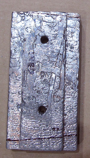
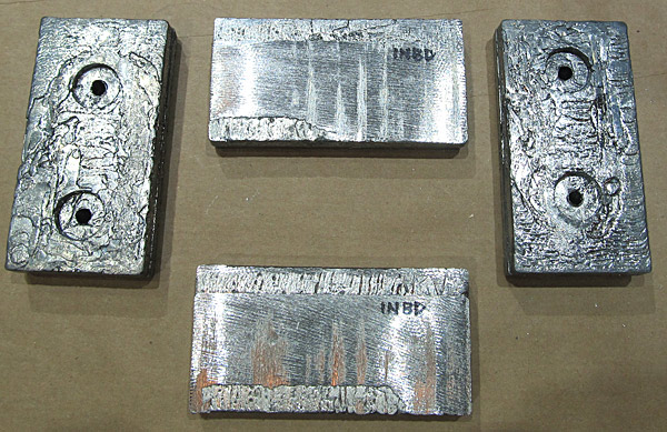
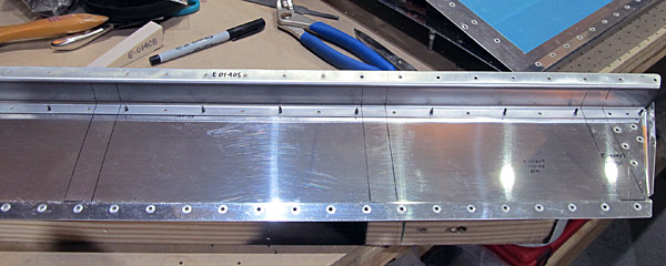
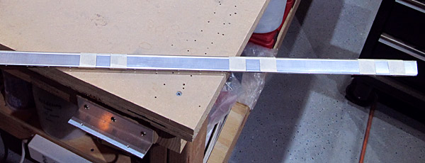
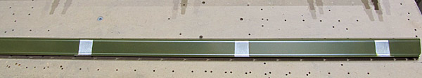
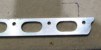
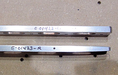
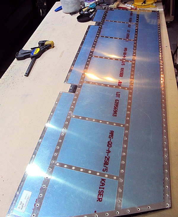
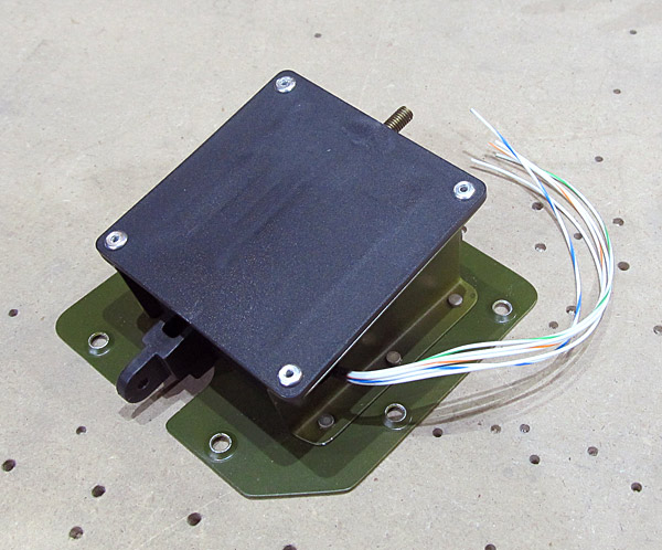
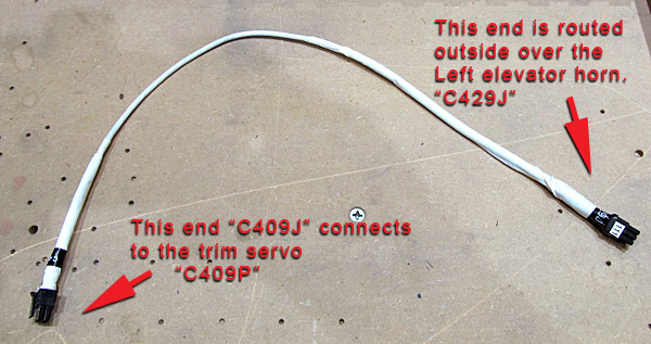
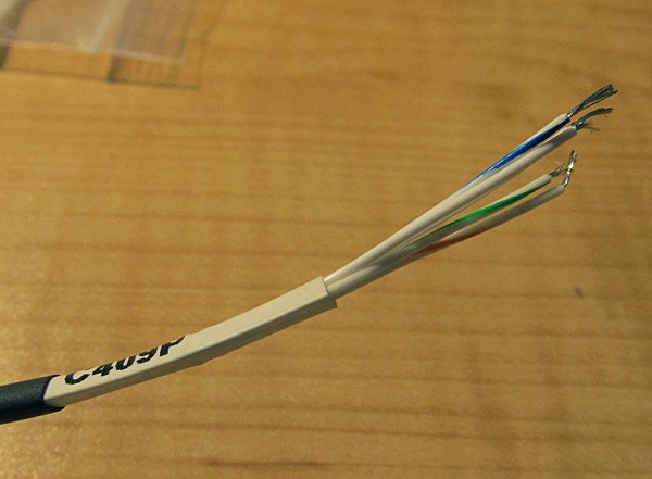
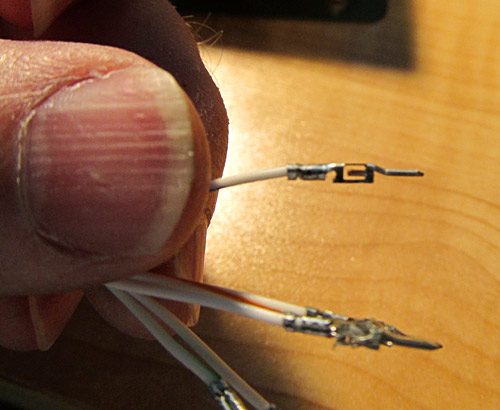
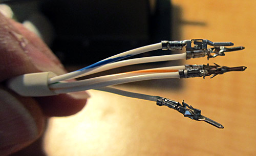
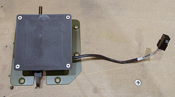
The parts included: (2) E-903 Outboard Tip Ribs,(1) E-00901B Left Bottom Skin, (1) E-00901A Left Top Skin, (2) E-913 Counterbalance Skins,(4) E-614 Counterbalance Weights, (1) E-00902-1L Front Spar, (4) E-910 Hinge Reinforcement Plates, (11) E-1008A Ribs, (12) E-1008B Ribs, (1) E-01409-L Servo Support C-Channel, (1) ES-MSTS-T3-12A Trim Servo, (1) E-01411 Reinforcement Doubler Brace, (1) WH-00073 Elevator Pitch Trim Harness, (1) E-01410 Trim Access Reinforcement Doubler, (1) WD-605-L-1 Elevator Horn, (1) E-00907-1L Rear Spar, (1) E-01423-L Trailing Edge, (8) E-00924 Trailing Edge Ribs, (1) E-01406 Trim Tab Top Skin, (1) E-01423-T Trailing Edge, (1) E-01405 Trim Tab Spar, (1) E-01401 Trim Pushrod, (3) E-01408 Trim Tab Ribs, (1) E-917 trim Tab Horn, (1) E-918 Trim Tab Horn, (1) E-01403 Trim Tab Hinge, (2) E-921 Gusset, (1) E-905 Left Root Rib, (1) WD-605-R-1 Elevator Horn, (1) E-00900A Right Top Skin, (1) E-00902-1R Front Spar, (2) E-904 Inboard Tip Ribs, (3) E-1022 Shear Clips, (1) E-00907-1R Rear Spar, (1) E-01423-R Trailing Edge, (1) E-009000B Right Bottom Skin, (1) E-01402 Trim Motor Cover, (1) E-01409 Servo Support C-Channel, and (1) E-00906-1 Right Root Rib.

Elevator Parts

These are all of the parts except for the four elevator top and bottom skins that are needed.


Elevator Ribs

The first thing the plans have you work on is the elevator ribs E-1008.

Van's provides the ribs in one pre-stamped piece and they want you to separate this piece into two separate parts.

Remove Blue Vinyl From Elevator Ribs

Just like every time before I start working on parts the protective blue vinyl needs to come off.

Separate Elevator Ribs

Using a sharpie pen I first drew guide lines by connecting the edges of the factory drilled guide holes. Then this will become two separate ribs after being cut out on the bandsaw.

The top half will become E-1008B and the bottom half will become E-1008A.

Separate Elevator Ribs

Once the lines have been drawn it's over to the bandsaw to cut out the two separate elevator ribs. I don't cut to the line but only close and then using a small file I trim the remaining excess material exactly to the line, that I way I have more control and don't overcut anything.

Debur Elevator Ribs

Deburring the elevator ribs with a small file.

Separated Elevator Ribs

The ribs are now deburred and the top half is labeled E-1008B and the bottom half is labeled E-1008A.

There are 24 of these elevator ribs. Twenty three ribs will be used and one E-1008B will be set aside.


Separating Elevator Shear Clips

Since I already had the bandsaw out I decided to cut out the four shear clips.

Van's has you draw guide lines from the top of the clip and angled down to the base of the clip on the pre-stamped metal.

There are three shear clips that will be used and the fourth one on the end that you see here is set aside.

Elevator Shear Clips

The three shear clips (E-1022) have been deburred.


Templates For Elevator Trailing Edge Ribs

There are eight trailing edge ribs (E-00924) and 3 trim tab ribs (E-01408) that must be fabricated from PVC foam blocks (Nycell PVC- 750 x 2 x 2.5).

The builder's plans have paper templates for the trailing edge ribs that have to be cut out and spray adhesive glued to the five foam blocks before cutting them out on the bandsaw.

* I used Loctite high performance spray adhesive "200" for this process. Double check that the measurement legend on the side of the template cutout page matches the actual dimensions called for.

Foam Elevator Trailing Edge Ribs

After cutting the trailing edge ribs out on the bandsaw, the edges have to be profiled to the edges of the template lines with sand paper.

I used sanding blocks with 220 grit sandpaper and continually checked that everything remained square as I sanded.


Elevator Trim Pushrod Parts

The elevator trim pushrod parts were labeled (E-01401A-R, E-01401A-L, and E-01401B) and then separated using the bandsaw.

As you can see they are kind of rough and need to be filed and deburred.

Elevator Trim Pushrod Parts Deburred

Here are the trim pushrod parts deburred.


Check Flange Of Inboard Tip Rib Is Square to Web

I cleaned the two elevator inboard tip ribs (E-904) with acetone and then checked to see that the flanges were 90° to the web.

Some minor adjustments had to be made and to do this I used seaming pliers and a handy jig that someone described how to build on line.

* Van'sAircraft had pre-fluted these inboard ribs so I had to work around them when making 90° bends.

Bending Flange Jig

This is a simple jig that I saw online built using a 2"x4", 2"x2", and simple hinge.

The 2"x4" base has an 11° angle cut over 90° to account for metal thickness and tension to make accurate 90° bends. The handle has a taper cut in the end and is rounded over so that no sharp creases are created in the metal you are bending plus it helps to clear any flared cutout holes that might be in the rib.

The handle is attached to the base with a simple hinge, (I just happened to have an old screendoor hinge but any hinge will do.)

Once you have this all assembled all that is needed is to clamp the jig to a flat table and start the bending process.

Using Bending Flange Jig

It is possible to over bend the metal slightly if you apply too much pressure on the handle.

It is best to practice on scrap aluminum parts with flanges before you start bending on those good parts first!

Practice makes perfect here.

I start out bending one small section at a time and if there are any flutes that are pre-existing or that you have created you need to work around them but the jig works well and maybe it might be worth your time to build one too.

Bending Flange Using Seaming Pliers

Of course seaming pliers work well too.

Fluting Inboard Elevator Tip Rib

After making the 90° bends in the ribs they will have to be fluted to insure all of the holes are aligned and the rib is as flat as possible.

I had to "unflute" some of the pre-fluted parts of this elevator inboard tip rib (E-904).


Check Flange Of Outboard Tip Rib Is Square to Web

I cleaned the two elevator outboard tip ribs (E-903) with acetone and then checked to see that the flanges were 90° to the web.

I used the same process as described for the inboard tip ribs above.

Fluting The Elevator Outboard Tip Rib

The elevator outboard tip ribs (E-903) were fluted after making the 90° bends.

Fluted The Elevator Tip Ribs

Here are the elevator tip ribs after fluting.

The edges have been deburred as well.


Deburring Elevator Counterbalance Skin

Now it is time to mock up the elevator counterbalance assembly and check for fit and begin the deburring process.

I removed the protective blue vinyl from the two counterbalance skins (E-913) first and deburred the edges with a small file.

Clecoing Elevator Counterbalance Parts Together

Next, the individual parts of the assembly get clecoed together. They include: E-904 inboard elevator tip rib, E-903 outboard elevator tip rib, and the E-913 elevator counterbalance skin.

Here they are all clecoed together. It's a tight fit.

Elevator Counterbalance Assembly
Final Drilling Elevator Counterbalance Parts

All of the pre-drilled holes are final drilled to #30 size through the elevator inboard tip rib (E-904).

* I know I've said it before but because of the precise nature of Van's pre-drilled holes I used a #30 reamer here to final size the holes....it's a very close and accurate fit!

Final Drilling Elevator Counterbalance Parts

There are 14 holes in the elevator counterbalance skin that do not get drilled at this time so they were masked off.
That is where the fiberglass tips will be attached to the elevator later. (Page 12-05 figure 3.)

The remaining pre-drilled holes common to the inboard (E-904) and outboard (E-903) elevator tip rib flanges and the elevator counterbalance skin (E-913) were final sized to #40 using a #40 reamer.


Debur And Scuff Elevator Tip Ribs

Just like everything else, once you put it together you have to take it apart again and start the deburring process of the final drilled holes.

I like to scuff the surfaces with gray "ultrafine" Scotchbrite pads in preparation for priming later.

These are the elevator inboard tip ribs (E-904).

Debur And Scuff Elevator Tip Ribs

These are the elevator outboard tip ribs (E-903).

This is the deburred elevator counterbalance skin (E-913).

* I decided to scuff the individual holes on the inside of the skins so that later when priming, just a small amount of paint needs to be used on the small dimpled spots and thereby (hopefully) cutting down a little on the overall weight.

Deburred Elevator Counterbalance Skin

Elevator Small Parts

There are some small parts that need to have the edges deburred so I am going slightly out of sequence in the plans here to do this and then I'll go back to the manual.

* These are going to have to be done eventually....right?

The parts include: (1) E-905 Left Root Rib, (1) E-01402 Trim Motor Cover, (1) E-01411 Reinforcement Doubler Brace, (2) E-921 Gusset, (1) E-01409-L Servo Support C-Channel, (1) E-01409-R Servo Support C-Channel, (1) E-01410 Trim Access Reinforcement Doubler, (4) E-910 Hinge Reinforcement Plates, (1) E-918 Trim Tab Horn, (1) E-917 trim Tab Horn, and (1) E-00906-1 Right Root Rib.

Elevator Small Parts

Here are the same parts edge deburred and scuffed in preparation for priming.

Trim Tab Horn Cutout Excess Material

The individual trim tab horns (E-918 and E-917) have to have some excess material removed so after drawing a layout line with a sharpie pen, I cut them out using the bandsaw.

Trim Tab Horn Parts

Here is what they look like when finished and deburred and scuffed with scotchbrite pads.

Elevator Small Parts

They will eventually be riveted together in this fashion.


Excess material needs to be removed from the elevator trim tab skins (E-01406 and E-01407). Basically you have to draw a line from the edge of the hole at the leading edge of the skin to the edge of the hole located at the trailing edge of the skin and that becomes the reference cut line.

I cut close to the layout line with aviator snips and then "fine tuned" the cut to the edge of the line with a small file. Then I deburred the cut.

Layout Line For Trim Tab Skin
Trimmed, Trim Tab Skin

This is the top elevator trim tab skin E-01406.

* Make sure that you label the inside of the skin so that you keep everything oriented correctly. (The close out tab for the top trim tab skin points down.)

Trimmed, Trim Tab Skin

This is the bottom elevator trim tab skin E-01407.

The close out tab for the bottom trim tab skin points up. (Of course I have the trim tab skin upside down here, but that's why you label everything...right?)


Primed All Elevator Ribs

After all of the elevator ribs (E-1008A and E-1008B) had been edge deburred the #30 and #40 pre-punched holes were final sized using #30 and #40 reams accordingly.

The holes were deburred and then all surfaces were Scotchbite scuffed with gray ultrafine pads, washed down with acetone, and then primed with Tempo A702 green zinc phosphate primer.

Primed All Elevator Internal Parts

All of the remaining small parts were scuffed with Scotchbrite gray ultrafine pads and primed with Tempo A702 green zinc phosphate primer.

These parts are: trim plate cover (E-01402), reinforcement doubler brace (E-01411), (3) shear clips (E-1022), (2) gussets (E-921), (4) hinge reinforcement doubler plates (E-910), trim access reinforcement doubler (E-01410), servo support "C" channel (E-0149-L), servo support "C" channel (E-01409-R), trim tab horn half (E-918), trim tab horn half (E-917), left root rib (E-905), and right root rib (E-906).


Jig For Cutting Excess Material From Counterweights

I next worked on the elevator counterweights (E-614), there are four of them.

The plans call for all of the pre-drilled holes to be final sized to #12, which I did, but then excess material has to be removed from two of the inboard counterweights.
(It's the tab you see sticking out from the main body.)

I made a simple jig to help steady the material in the bandsaw and also give a nice flush cut.

*Be sure to have a piece of thin plywood under the lead bar when cutting because if you don't, the heat from the sawing action will melt the lead which in turn will jam up the bandsaw blade. The plywood cleans the blade and prevents this from happening.

Cutting Excess Material From Counterweights

Here I am trimming the counterweight on the bandsaw.

Cutting Excess Material From Counterweights

The counterweights also have to be profiled to fit inside of the elevator tip ribs (E-903 and E-904).

The plans give detailed instructions on how to layout the cut lines but basically the leading edges of the weights are tapered to match the leading edges of the ribs that they fit inside of.

*Don't forget to use a thin piece of plywood under the weight when trimming to prevent the sawblade from being "gummed up"!

Cutting Excess Material From Counterweights

Here are the elevator counterweights (E-903 and E-904) final sized and drilled.


Mark Ream Hole Location For Left Elevator Spar

One of the elevator front spars (E-00902-1) has to have two pre-punched #30 holes step drilled enlarged to allow electrical connections to be passed through to connect to the trim tab servo (ES-MSTS-T3-12A).

The top hole is to be enlarged to ⅝" and the bottom hole is to be enlarged to ⅜".

Reamed Holes On Left Elevator Spar

This is what it looks like after the holes have been enlarged. They will later have grommets placed on them to protect the wires running through.

*The spar now is to be relabled and becomes (E-00902-1L) the elevator left front spar.


Countersink And Fabricate Elevator Trim Pushrod

I next moved on to assemble the elevator trim pushrod assembly.

It is made from three parts: (E-01401A-L, E-01401A-R, and E-01401B).

First all of the pre-punched #30 and #40 holes were final sized using #30 and #40 reams and then all of the #40 holes on the outside halves of the (E-01401A-L and E-01401A-R) elevator trim pushrod arms were machine countersunk to receive AN426AD3-4 rivets.

Countersink And Fabricate Elevator Trim Pushrod

Here is the finished elevator trim pushrod assembly. It was assembled using the double flush rivet method.

*Alternating the rivet direction will prevent the pushrod from warping.


Remove Blue Vinyl From Elevator Skins

I removed the protective blue vinyl from the elevator skins: left elevator top skin (E-00901A), left elevator bottom skin (E-00901B), right elevator top skin (E-00900A), and right elevator bottom skin (E-00900B).

Debur Elevator Skins

Let the edge deburring process on the skins begin!

Bend Line For Elevator Skin Closeout Tab

Using a fine tipped Sharpie pen, Van's instructs you to draw bend lines to create "closeout" tabs on the left elevator top skin (E-00901A) and left elevator bottom skin (E-00901B).

The "closeout" tab on the left elevator top skin (E-00901A) will be bent down and the "closeout" tab of the left elevator bottom skin (E-00901B) will be bent up.

The insides of the skins are to be labled to avoid confusion duriing the assembly process.


Bending Elevator Skin Closeout Tab

I final drilled all of the #30 and #40 pre-punched holes on the elevator skins and trim tab skins and then proceeded to create the closeout tab on the left elevator top skin (E-00901A).

*The plans instruct you to place the top left elevator skin bend reference line 1/64" beyond one corner of the work bench with the trailing edge of the skin just overhanging the other edge of the bench and then clamp everything down with a block of wood.

Using another block of wood the bend is made with even pressure to create the bend.

Bending Elevator Skin Closeout Tab

I used a rubber mallot to finish the bend and seaming pliers to fine tune the bend to 90°.

Bending Elevator Skin Closeout Tab

The closeout tab is done basically the same for the left elevator bottom skin (E-00901B) but now the bend reference line is placed 1/32" over the edge of the workbench.

Bending Elevator Skin Closeout Tab

The tabs are each bent towards the inside of the skin and the top skin closeout tab overlaps the bottom skin closeout tab later on.


Trimming Right Elevator Rear Spar Trimming Right Elevator Rear Spar

The right elevator rear spar (E-00907-1R) has to have 11/16" excess material trimmed from it so reference lines were drawn in order to cut it to length.

*This is so the right rear spar will fit flush against the right elevator root rib (E-00906-1).

Trimming Right Elevator Rear Spar

I used the bandsaw to make the cut. This now becomes (E-00907-1R) and the left elevator rear spar is relabled to (E-00907-1L).

The cut was filed to the line and deburred.


Labeling Elevator Trim Hinge

The piano hinge (part number AN257-P2) used to attach the elevator trim tab to the elevator assembly needs to be marked so that the orientation of the two halves can be maintained during the construction process so Van's instructs you to label the front half and aft half.

*Make sure that the center hinge connection loop is facing down.

The part is then redesignated to be (E-01403).

Pilot Holes For Trim Hinge

Two #40 pilot holes were drilled into the separate hinge halves.

*Be careful here: The forward half of the hinge has a hole drilled 3/16" from the front leading edge and 3/16" inward from the left edge.

The aft hinge half has a hole drilled 3/16" from the aft trailing edge but 1/4" inward from the left edge.


Final Drilling Holes On Elevator Spars

I final drilled all #30 and #40 pre-punched holes on the elevator front spars (E-00902-1L) and (E-00902-1R).

Final Drilling Holes On Elevator Spars

I final drilled all #30 and #40 pre-punched holes on the elevator rear spars(E-00907-1L) and (E-00907-1R).

Cleco Elevator Spars To Elevator Bottom Skins

After the front elevator spars (E-00902-1L) and (E-00902-1R) were deburred they were clecoed in place to their respective bottom elevator skins (E-00901B) and (E-00900B).


Elevator Mockup

Here is where the fun begins because now everything is mocked up to check for fit and also to continue the build process....It's beginning to look like an elevator!

The right elevator contains all of the (E-1008) ribs, (E-00902-1R) front spar, (E-00906-1) right root rib, (E-00907-1R) rear spar, (E-921) gusset, and (E-1022) shear clip clecoed to the right bottom elevator skin (E-00900B).

The left elevator contains all of the (E-1008) ribs, (E-00902-1L) front spar, (E-00905) left root rib, (E-001410) trim access reinforcement doubler, (E-1008B) upper rib, (E-01411) reinforcement doubler brace, (E-00907-1L) rear spar, (E-921) gusset, and (E-1022) shear clip clecoed to the left bottom elevator skin (E-00901B).


Elevator Trim Tab Hinge Construction

The hinge pin was removed from the trim tab hinge (E-01403) and using the pilot hole drilled earlier, the hinge was clecoed into place on the bottom side of the top flange of the left elevator rear spar (E-00907-1L).

*I drew lines on the hinge with a sharpie to make sure that when I clamped the hinge to the spar that everything remained in perfect parallel alignment to the flange before proceeding to the next step.

Elevator Trim Tab Hinge Construction

After clamps were evenly spaced along the hinge, I drilled #40 holes into the hinge using the left rear spar (E-00907-1L) pre-punched holes as guides.

Elevator Trim Tab Hinge Construction

Clecos were placed in each match drilled hole as the drilling progressed from left to right.

Elevator Trim Tab Hinge Construction

After the #40 holes were drilled into the trim tab hinge halves (E-01403), a line was drawn on the forward hinge half, using the beveled end of the rear elevator spar (E-00907-1L) as a guide, and the excess material was trimmed from the hinge halves so that they would be flush with the rear spar (E-00907-1L) and trim tab spar (E-01405) ends.

The picture here shows both halves after the ends were trimmed and deburred.

Elevator Trim Tab Hinge Construction

Here I am match drilling the #40 holes into the aft hinge half using the pre-punched holes in the trim tab spar (E-01405) as guides.


Final Drill Gussets

The #30 holes in the small gussets (E-921) and the corresponding holes that attach them to the left elevator rear spar (E-00907-1L) and the right elevator rear spar (E-000907-1R) and the left elevator root rib (E-00905) and right elevator root rib (E-00906-1) were final drilled, deburred, and clecoed back in place.


Primed Elevator Tip Ribs

I ran out of ⅛" cleco clamps so while I was waiting to receive them in the mail I washed the elevator tip ribs (E-903-1), (E-904-1), (E-903-2), and (E-904-2) with acetone and primed them with Tempo A702 green zinc phosphate primer.

Locate Trim Tab Ribs On Trim Tab

While I was waiting, I clecoed the trim tab spar (E--1405) to the bottom elevator trim tab skin (E-01407) so that the location of the foam ribs (E-01408) for the trim tab assembly could be determined.

*These areas will be later scuffed with 150 grit aluminum oxide sandpaper so that the foam ribs can be glued into place with tank sealant.

Locate Trim Tab Ribs On Trim Tab

Reference lines were drawn on the bottom elevator trim tab skin (E-01407) and the elevator trim tab spar (E-01405) with a sharpie pen at 3/16", 7 5/8", and 16 3/16" to the left of the trim tab edge line.

Locate Trim Tab Ribs On Trim Tab Spar

The areas to be scuffed were masked off to be scuffed with the 150 grit aluminum oxide sandpaper.

Primed Trim Tab Spar

After scuffing the areas masked off, the elevator trim tab spar (E-01405) was primed with Tempo A702 green zinc phosphate primer.


Elevator Tip Assembly

The right and left elevator tip assemblies (E-903, E-904, and E-913) were clecoed together and then clecoed to their respective elevator assemblies.

Elevator Tip Assembly

All of the #30 holes common to the elevator front spars (E-00902-1L and E-00902-1R), the tip rib assemblies, and the shear clips (E-1022) were final drilled to size.

The elevator top skins (E-00901A and E-00900A) were then clecoed to their respective assemblies.

Counterweight Skin Position

*Be sure that the counterweight skin (E-913) lies under the elevator skin as per the builder's plans note on page 9-22.

Elevator Trailing Edge Wedge

The elevator trailing edge wedges (E-01423-L and E-01423-R) were clecoed into position at the trailing edges of each elevator and using a sharpie pen, the inboard and outboard ends of the elevator skins were traced onto the wedges so that excess material could be trimmed from them.

Elevator Trailing Edge Wedge

The outboard edge of the trimmed elevator trailing edge wedge (E-01423-L)

Elevator Trailing Edge Wedge

The inboard edge of the trimmed elevator trailing edge wedge (E-01423-L)

Elevator Trailing Edge Wedge

In addition to trimming excess material from the trailing edge wedges, the outboard ends of each have to be profiled so that later in construction when the fiberglass elevator tips are installed, the thickness of the wedge matches that of the fiberglass tip.

*I determined that my outboard edge ends needed to be tapered to 3/32" thickness (starting from a distance of 1-3/32" from the end) of the wedge piece.

(E-01423-R) in this photo shows the taper for the right trailing edge wedge. The left trailing edge is similar in profile.

I used a file and 220 grit sandpaper to create the taper.


Marking For Foam Ribs E-00924

The top left elevator skin (E-00901A) was removed so that I could mark the locations of where the foam elevator trailing edge ribs (E-00924) would eventually be glued into place with tank sealant.

There are two of them in the left elevator, one located 5 ¼" from the inboard edge of the elevator and the other is located 11 ¾" from the inboard edge.

While I was at it, I marked the location on the left elevator skin where the trailing edge wedge (E-01423-L) would be because later in construction these places will need to be scuffed with 150 grit aluminum oxide sandpaper so that the adhesives will work on the bare aluminum skin.

Left Elevator Closeout Tab

The foam elevator trailing edge ribs (E-00924) were temporarily taped into position near the closeout tabs and the outboard section of the left elevator.

The left elevator top and bottom skins (E-00901A and E-901B), the trailing edge wedge (E-01423L), and inner shear clip (E-1022) were all clecoed back together.

Left Elevator Closeout Tab

Three #30 holes were match drilled into the closeout tabs of the left elevator top and bottom skins (E-00901A and E-901B), starting with the already existing factory pre-punched hole.

*Make sure that the left elevator top skin (E-00901A) overlaps the left elevator bottom skin (E-00901B).

Left Elevator Horn

The clecoes securing the left elevator root rib (E-905) to the left elevator front spar (E-00902-1L) were removed and the left elevator horn (WD-605-L-1) was clecoed into position onto the root rib and front spar.

Six #30 holes were final drilled common to the front spar (E-00902-1L) and the elevator horn (WD-605-L-1), and six #30 holes were final drilled common to the left elevator root rib (E-905) and the elevator horn (WD-605-L-1).


Marking For Right Elevator Foam Ribs E-00924

The top right elevator skin (E-00900A) was removed so that I could mark the locations of where the foam elevator trailing edge ribs (E-00924) would eventually be bonded into place with tank sealant.

There are six of them in the right elevator. The locations are determined as measured from the outboard edge of the right elevator. The locations are 9 7/16", 17 1/2", 26 1/16", 34 3/8", 41 5/8", and 48 7/8".

While I was at it, I marked the location on the right elevator skin where the trailing edge wedge (E-01423-R) would be because later in construction these places will need to be scuffed with 150 grit aluminum oxide sandpaper so that the adhesives will work on the bare aluminum skin.

Right Elevator Horn

The right top elevator skin (E-00900A) and right elevator trailing edge wedge (E-01423-R) were clecoed back into place.

The clecoes securing the right elevator root rib (E-00906-1) to the right elevator front spar (E-00902-1R) were removed and the right elevator horn (WD-605-R-1) was clecoed into position onto the root rib and front spar.

Six #30 holes were final drilled common to the front spar (E-00902-1R) and the elevator horn (WD-605-R-1), and six #30 holes were final drilled common to the left elevator root rib (E-00906-1) and the elevator horn (WD-605-R-1).


Labeled All Parts

All of the parts were labeled so that when everything is disassembled they can be reassembled in the same position.

Primed Spars

The elevator spars were washed with acetone and primed with Tempo A702 green zinc phosphate primer.


Edge Break Elevator Skins

The trailing edges of the elevator skins received an edge break using the edge forming vise grips from Cleaveland Aircraft Tool.

The leading edges of the top elevator skins (E-00901A and E-900A) received an edge break as well since they will overlap the bottom skins when the leading edge is formed later in construction.

The plans have you put an edge break on the trailing edge of the counterbalance skins (E-913) so I did that at this time too.

*The edge break is done towards the inside of the skins.

Edge former tool

These are the edge forming vise grips.

E913 Counterbalance Dimpling

Here I taped off the seven holes on the tops and bottoms of the elevator counterbalance skins (E-913) which will later receive the elevator tip fairings (E-912) and then dimpled all of the #40 holes.


Scuffing Trim Tab Skins

The areas where the elevator trim tab skins (E-01407 and E-01406) will receive foam ribs were taped off and scuffed with 150 grit aluminum oxide sandpaper. The trailing edge wedge area will need to be scuffed as well because this is where the parts will be bonded to later in construction.

Scuffing Trim Tab Skins

Let the "scuffing" begin!

Scuffing Trim Tab Skins

This is the trim tab scuffed, all of the skins were washed with acetone.

Scuffing Trim Tab Skins

What the heck... I scuffed all of the areas on the elevator skins (E-00901A, E-00901B, E-00900A, and E-900B) that will later receive foam trailing edge ribs (E-00924) bonded using tank sealant and the areas where the trailing edge wedges (E-01423's) will be too. I washed each skin with acetone.


Dimpling Elevator Skins

There are six holes on the tops and bottoms of the elevator skins (E-00901A, E-00901B, E-00900A, and E-900B) that do not receive dimples. This is where the elevator tip fairing (E-912) will be attached later so I placed tape over those areas so I wouldn't have any "boo boos" when I start the dimpling process.

Dimpling Elevator Skins

Let the dimpling begin...

I used the DRDT2 to dimple the #40 holes in the center of the elevator skins.

Dimpling Elevator Skins

I used a 3/32" modified male dimple die and a reduced diameter female dimple die in our hand squeezer to dimple the trailing edge of the elevator skins in order to protect the pre-formed bend made by Van's.

*There is a special note about this on page 09-28 in the plans.

Dimpling Elevator Skins

Dimpled skins!

Dimpling Elevator Shear Clip

The two #30 holes in the left elevator inboard shear clip (E-1022) was dimpled next using our DRDT2 dimpling machine.

The closeout tabs corresponding to the shear clip were #30 dimpled in the left elevator top and bottom skins (E-00901A and E-00901B) with our hand squeezer.

Dimpling Elevator Tip Ribs

There are two leading edge, #30 holes in each of the elevator tip ribs (E-903 and E-904) that need to be dimpled so that when the counterweights are installed they will lay flat against the web structure.

*Pay special attention here; the inboard side of the rib web gets the flush side of the dimple.

This is the outboard side of (E-903).


Dimpling Elevator Trim Tab Closeout Tabs

The closeout tabs on each end of the the elevator trim tab skins (E-01406 and E-1407) were 3/32" dimpled using the hand squeezer.

*The #40 holes will be later drilled out to a new size using a #33 drill bit.

Temporary Taping Of Foam Ribs In Elevator Trim Tab

The trim tab spar (E-01405) was clecoed to the bottom elevator trim tab skin (E-1407) and then the trim tab foam ribs (E-01408) were temporarily taped into position (to maintain airfoil shape for the next step in construction.)

Mockup Of Elevator Trim Tab

The elevator trim tab top skin (E-01406) was clecoed into place as well as the trim tab trailing edge wedge (E-01423-T).

The #40 dimpled holes in the trim tab closeout tabs were #33 final drilled (one at a time) on both ends of the trim tab assembly to that later in construction (MK-319BS) rivets can be set.

Mark Elevator Trim Tab Edge Wedge

Using a Sharpie, the inboard and outboard edges of the trim tab skin edges were transferred to the trailing edge wedge (E-01423-T) so that it could be trimmed to final size.

The whole assembly was then disassembled.

Mark Elevator Trim Tab Edge Wedge

Marked the elevator trim tab trailing edge wedge (E-01423-T) outboard end.

Mark Elevator Trim Tab Edge Wedge

Marked the elevator trim tab trailing edge wedge (E-01423-T) inboard end.

Mark Elevator Trim Tab Edge Wedge

Trimmed and deburred the elevator trim tab trailing edge wedge (E-01423-T) outboard end.

Mark Elevator Trim Tab Edge Wedge

Trimmed and deburred the elevator trim tab trailing edge wedge (E-01423-T) inboard end.

Dimpling Elevator Trim Tab Skins

I used a 3/32" modified male dimple die and a reduced diameter female dimple die in our hand squeezer to dimple #40 holes in the trailing edges of the elevator trim tab skins (E-01406 and E-1407) in order to protect the pre-formed bend made by Van's.

Dimpling Elevator Trim Tab Skins

All dimpled!


Dimpling Elevator Ribs

After dimpling all of the #30 and #40 holes, according to the builder's plans (page 9-10), in the elevator tip ribs (E-903 and E-904) I moved along and dimpled all of the #40 holes in the elevator ribs (E-1008A's).

Dimpling Elevator Ribs

The dimpled elevator ribs (E-1008B's).

Dimpling Elevator Front Spars

All of the #40 holes in the elevator front spars (E-00902-1L and E-00902-1R) were dimpled, plus there are three additional #40 holes in the inboard web section of the front spars that require dimpling as well.

This is where the root ribs will eventually be riveted to the spar.

Primed Spars

All of the #40 holes in the rear elevator spars (E-00907-1L and E-00907-1R) were dimpled.

*Be sure not to dimple the holes in the left elevator spar where the forward half of the trim tab hinge (E-01423-L) will be located because these holes will have to be machine countersunk later in construction.

Dimpling Elevator Inner Parts

The #40 holes in the elevator root ribs (E-905 and E-00906-1), the #27 and #40 holes in the trim access reinforcement doubler (E-01410), trim reinforcement doubler brace (E-01411), trim cover plate (E-01402), nutplate fasteners (K1100-06), trim tab horns (E-917 and E-918), and the bottom flange of the trim tab spar (E-01405) were all dimpled.


*A number six screw dimple die set is used to dimple the #27 dimples called for in the dimpling process on page 09-11.


Priming Skin Dimples

All of the elevator skins (E-00901A, E-00901B, E-00900A, E-00900B, E-01406, and E01407) dimples were washed with acetone and primed with PTI primer gray zinc phosphate self etching primer.


Countersinking Elevator Trailing Edge Wedges

Time to machine countersink the trailing edge wedges (E-01423-L, E-01423-R, and E-01423-L).

Let the countersinking of all of the trailing edge wedges, beginning with the left elevator wedge (E-01423-L), begin!

Countersinking Elevator Trailing Edge Wedges

Countersinking Elevator Rear Spar

The forward half of the elevator trim tab hinge (E-01403) was clecoed into place under the left rear elevator spar (E-00907-1L) upper flange and all of the #40 holes common to both were machine countersunk in order to accept dimples made in the left elevator top skin (E-00901A).

Countersinking Elevator Trim Tab Spar

The aft half of the elevator trim tab hinge (E-01403) was clecoed into place under the elevator trim tab spar (E-01405) top flange and all of the #40 holes common to both were machine countersunk in order to accept dimples made in the elevator trim tab skin (E-01406).


Rivet Nutplates To Trim Reinforcement Doubler

Five nutplates(K1100-06) were riveted to the trim access reinforcement doubler (E-01410) using our pneumatic squeezer with a longeron yoke to set AN426AD3-3.5 rivets.

*Two nutplates will be installed later in construction.

Rivet Gusset to Root Rib

The gusset (E-921) was riveted to the left elevator root rib (E-905) using the pneumatic squeezer to set AN470AD4-4 rivets.

Riveted Tip Ribs Together

The elevator tip ribs (E-903 and E-904) were clecoed together and riveted together using our pneumatic squeezer.

Fourteen AN470AD4-4 and two AN426AD4-4 rivets were used per each tip assembly.


Riveted Doublers To Elevator Spars

Two sets of reinforcement plates (E-910) and four nutplates (K-1000-6) were riveted to each of the elevator front spars (E-00902-1L and E-00902-1R) with the pneumatic squeezer.

*Be careful here because there are different size rivets used. AN470AD4-4 are used on the plates but AN470AD4-6 rivets are used on the nutplates.

Riveted Doublers To Elevator Spars

The elevator tip assemblies were riveted to the elevator front spars (E-00902-1L and E-00902-1R) with a pneumatic squeezer and the inner web area rivets were set using the rivet gun with a ⅛" cupped 10° offset rivet set and a tungsten bucking bar.

AN470AD4-4 rivets were used.

The left elevator root rib (E-905) was riveted to the left front elevator spar (E-00902-1L) using a hand squeezer to set AN426AD3-3.5 rivets and the right elevator root rib (e-00906-1) was riveted to the right front elevator spar (E-00902-1R) also using a hand squeezer to set AN426AD3-3.5 rivets.

Bushing Installed On Left Elevator Spar

A snap bushing (SB625-8) was installed onto the left front elevator spar (E-00902-1L). This is used to protect the electrical wiring of the trim tab motor.


Cleco Counterbalance Skins In Place

The elevator counterbalance skins (E-913) were clecoed to the elevator tip ribs (E-903 and E904) and the skins were then riveted to the ribs using our pneumatic squeezer to set AN426AD3-3.5 rivets.

Rivet Counterbalance Skins

*Be careful not to rivet the four holes on the top and bottom of each counterbalance skins because later in construction the elevator skins have to be lifted in order to gain access to rivet these in place (see page 09-22 in the builder's plans).


Rivet Elevator Horn

The right and left elevator horns (WD605-R-1 and WD605-L-1) were clecoed to the right and left elevator spars (E-00902-1R and E-00902-1L ) and the right and left elevator root ribs (E-00906-1 and E-905) and riveted into place using the pneumatic squeezer to set AN470AD4-4 rivets.


Cleco Elevator Trim Tab Spar To Skin

The elevator trim tab horns (E-917 and E-918), trim tab bottom skin (E-01407), and the elevator trim tab spar (E-01405) were clecoed together in preparation for riveting.

*Be careful to note that where the two individual trim tab horns intersect the trim tab spar, the plans call for a longer rivet. Use an (AN426AD3-4) rivet here.

I used our pneumatic squeezer to set the rivets that attach the horns to the rest of the assembly.

Two Special Rivets

These are the two rivets that I am talking about. (*See page 09-14, figure 1.)

Back Rivet Elevator Trim Tab Spar To Skin

Back rivet the rest of the trim tab assembly together using AN426AD3-3.5 rivets.

*It helps to elevate the whole assembly while back riveting because the trim tab horns "stick down" and the piece won't sit flat on the table.

Finished Riveting Elevator Elevator Trim Tab Spar To Skin

Trim Tab Horns To Elevator Trim Tab

Back riveting complete!

Cleco Elevator Ribs To Rear Elevator Spars

Time to cleco all of the elevator bottom ribs (E-1008B's) to the elevator left and right rear spars (E-00907-1L and E00907-1R) respectively.

The three elevator shear clips (E-1022) and one elevator gusset (E-921) were also clecoed to their respective rear spars as well.

Riveting Elevator Ribs To Rear Spar

All of the AN470AD4-4 rivets were set using our pneumatic squeezer.

Finish Riveting Elevator Ribs To Rear Spar

Nice!


Clecoed Left Elevator Top Skin To Rear Spar

I clecoed the (E-1008B) elevator ribs, the forward half of the trim tab hinge (E-01403), and the left elevator rear spar (E-00907-1L) to the left elevator top skin (E-00901A) together and then aligned and clamped them along the edge of our workbench.

*Be sure that the hinge is clecoed under the top flange of the rear spar.

Make sure to shim the ribs up from the workbench about 5/32" or 4mm like the plans say too. (I had a thin piece of aluminum sheet metal along with an aluminum yard stick that worked well here.)

There are three holes on the inboard elevator that do not get riveted at this time so be careful not to rivet them.


I used our hand squeezer to set the AN426AD3-4 rivets in the hinge area but had to switch to our 3x rivet gun and use a tungsten bucking bar to set the remainder of the rivets (AN426AD3-3.5) along the rest of the rear spar channel towards the outboard section of the left elevator.

Clecoed Elevator Ribs To Right Bottom Elevator Skin

The right elevator ribs (E-1008B), the right elevator rear spar (E-00907-1R), and the right elevator bottom skin (E-00900B) were clecoed together and the rear spar was riveted to the skin with AN426AD3-3.5 rivets set with the 3x rivet gun and a tungsten bucking bar.

*Be sure not to rivet the six outboard and three inboard rivets on the rear spar at this time.

Don't forget to shim the ribs up from the workbench too.

Elevator Skins Riveted To Rear Spars

Once the rear spars were riveted to the skins, everything was flipped over onto the workbench in preparation for back riveting the ribs to the skins.

Long Back Rivet Plate

I like to use the four foot back rivet plate I made during the rudder build to back rivet the ribs into place. It is long enough to see on the other side of the skin and keeps us oriented during the back riveting process.


Bucking Elevator Ribs To Skins

My wife is much better than I am when it comes to using the rivet gun so she back riveted the ribs in place during this part of the build.

Here she is back riveting the elevator ribs (E-1008B) to the left elevator top skin (E-00901A) with AN426AD3-3 rivets.

*We found that we had to switch to our 12" extension back rivet set in order to clear the long tab of the rib because the spring holding the back rivet set to the rivet gun tended to hit and offset the rib somewhat in those areas of the ribs.

It also helped to remove the protective plastic guard from the set while in this area too.


After back riveting the ribs on the left elevator top skin we moved on and back riveted the elevator ribs (E-1008B) to the right elevator bottom skin (E-00900B) with AN426AD3-3 rivets.

Finish Riveting Elevator Ribs To Skins

Next is to back rivet the left elevator ribs (E-1008A) to the left elevator bottom skin (E-00901B) with AN426AD3-3 rivets and the right elevator ribs (E-1008A) to the right elevator top skin (E-00900A) with AN426AD3-3 rivets.


Rivet These Two Rivets First

The #40 holes in two (K1100-06) nutplates were dimpled and then the trim access reinforcement doubler (E-01410) was clecoed into place on the left elevator bottom skin (E-00901B).

There are two AN426AD3-3.5 rivets that must be riveted first here because if you don't, you won't be able to access them later because the reinforcement doubler brace (E-01411) will be in the way.

I used our pneumatic squeezer to set these two rivets.

Clecoed Elevator Trim Doubler Brace To Doubler

The reinforcement doubler brace (E-01411) was clecoed into position onto the trim access reinforcement doubler (E-01410) and the left elevator bottom skin (E-00901B), as well as the two (K1100-06) nutplates.

Blind Rivet Set To Reinforcement Doubler Brace

A single LP4-3 blind rivet was used to rivet the reinforcement doubler brace (E-01411) to the trim access reinforcement doubler (E-01410) using our CherryMax G-27 hand rivet gun.


Use Tungsten Bucking Bar In Tight Spaces

The trim access reinforcement doubler (E-01410) was back riveted to the left elevator bottom skin (E-00901B) using AN426AD3-3.5 rivets and a 3x rivet gun and our short 16" back rivet plate.

I back riveted the (K1100-06) nutplates and reinforcement doubler brace (E-01411) to the trim access reinforcement doubler (E-01410) last because in this area I had to use my 1" x 1" x 2 ¼" tungsten bucking bar as a back rivet plate. This was because this area is below the surface of the left elevator bottom skin and a regular backing plate would not work and would most likely "ding" a skin!

I used AN426AD3-4 rivets here because the AN426AD3-3.5 rivets seemed a bit too short.

Elevator Trim Access Doubler Riveted In Place

Everything is riveted in place now!

Elevator Rear Spars And Skins Clecoed In Place

The top left and right elevator skins (E-00901A and E-00900A) were positioned over the left and right elevator bottom skins (E-00901B and E-00900B) as indicated in the builder's plans (page 09-19) making sure that the rib "tabs" were properly aligned and then I clecoed the elevator ribs (E-1008A and E-1008B) together.

The left bottom elevator skin (E-00901B) was clecoed to the left rear elevator spar (E-00907-1L) and the top right elevator skin (E-00900A) was clecoed to the right rear elevator spar (E-00907-1R) in preparation to rivet the rear spars to the skins.

*I'll come back to this section, but now a slight deviation, as I go back to the elevator trim tab to finish it's construction.


Flat Surface For Trim Tab Construction

I am using a ¾" x 2 foot x 4 foot piece of MDF to assemble the elevator trim tab on because I need to move everything into the house so that the tank sealant used will cure properly. The shop temperature is too cold for that.

Tank Sealant

Van's Aircraft has you adhere the foam ribs (E-01408) to the trim tab skin using tank sealant (MC-236-B1/2).

This is the sealant; it is made by Flamemaster (P/N PSI CS-3204 B-2) and they say in the literature that it needs to cure at temperatures above 70°F for several days in order to really cure properly.

My shop temperatures are routinely below 40°F at night this time of year so that's why I'll be moving the trim tab to a warmer place after assembly.

The tank sealant isn't too bad to work with, I did keep it inside the warmth before using it so that it wasn't really thick.

There is a shelf life of 9 months from date of production so you have to be aware of that and once mixed you have about a 2 hour potlife before it sets up and is unworkable.

The smell isn't as bad I thought it would be but it does have an odor once mixed. It is pretty sticky stuff though and you have to be careful to not get it all over everything.

It didn't stink up the house either once I moved it there for curing purposes....so that's a relief!

Getting Ready For Final Trim Tab Construction

I got all of the parts together and washed the scuffed bare metal surfaces with isopropyl alcohol before mixing the sealant.

Here are the parts: foam ribs (E-01408), trim tab skins (E-01406 and E-01407), trim tab spar (E-01405), aft half of trim tab hinge (E-01403), trim tab trailing edge wedge (E-01423-T), bonding tape for wedge (3M F9460 PC VHB), rivets for leading edge AN426AD3-4, and clecos.

*Don't forget to prop up the trim tab above the table. The trim tab horns stick down and won't allow the trim tab to lay flat during contruction. Later the whole piece can be flipped over so that a weighted board can be place over the skin during the curing process.

Bonding Trailing Edge Wedge Of Trim Tab In Place

I started out by bonding the trailing edge wedge (E-01423-T) to the bottom trim tab skin (E-01407) with 2 layers of the double sided 3M F9460 PC VHB tape on the top and bottom of the wedge.

It's good stuff but after doing the rudder trailing edge wedge I find it better to use two layers per side than one....it's really thin!

Bonding Foam Ribs In Place

Here the foam ribs (E-01408) are glued into place using the sealant. I spread it onto the ribs with popsicle sticks.

Elevator Trim Tab Clecoed Together

The elevator trim tab top skin (E-01406), trim tab spar (E-01405), aft half of trim tab hinge (E-01403), and the trim tab trailing edge wedge (E-01423-T), were clecoed together.

The leading edge of the elevator trim tab is riveted together with AN426AD3-4 rivets. It's a tight space but if you can flip the unit over with the trim tab horns facing up you can get the rivets set with a hand squeezer or pneumatic squeezer.

I used a hand squeezer with a three inch yoke.

*Double check to make sure the trim tab hinge is set under the top flange of the trim tab spar.

Weights On Elevators

The trim tab was moved into the house with warmer temperatures and weighted boards were placed onto the skins so that during the curing process for the adhesives everything would remain flat and straight.

*It takes 4.6 days for the sealant to cure and three days for the 3M tape to cure.


Riveting Rear Spar To Left Elevator Bottom Skin

Back to riveting the elevator rear spars to the skins...

I riveted the left elevator bottom skin (E-00901B) and the left rear elevator spar (E-00907-1L) together using AN426AD3-3.5 rivets set with the pneumatic squeezer.

*The open section where the trim tab will be is the only place you can use the pneumatic squeezer in.

Finish Riveting Rear Spar To Left Elevator Bottom Skin

Nice!


Cradle For Trim Tab

The five days of curing time is up so now it's time to set the trailing edge rivets...

I made a simple cradle to set the trim tab in so that setting the trailing edge rivets would be a little easier.

Trim Tab In Cradle

Special Trailing Edge Rivet Set

Cleaveland Aircraft Tools makes a special set of dies that's perfect for double flush setting the trailing edges of the elevator and trim tab.

It's called the RV-14 Safety Pin Squeezing Tool and is item number (14-1801). It sells for $29.50 at the time of this post and is well worth the cost. The dies are ground at 4° to match the profile of the trailing edge wedge and held in alignment with the safety pin.

*I have seen these selling elsewhere so shop around you may find a better deal.

After double flushing the trailing edge wedge there three rivets on each of the "closeout tabs" that need to be set. MK-319-BS countersunk blind rivets are used here and they were set using the CherryMax G-27 hand rivet gun.


Practice Rivet Channel

Before riveting the hard to reach rivets in the elevator rear spars I made a practice aluminum channel to practice using the specialty made long bucking bar. It's 1" x 1" x 12" channel and I bent the edges to approximate the angles of the rear spar.

Clecoed Rear Spar Left Elevator Ready For Partial Riveting

The left elevator is the first to be riveted together, remember that there are six rivets that don't get set at this time. They are located at the outboard side of the elevator.

We are using AN426AD3-3.5 rivets.

Cleaveland RV14 Empennage Bucking Bar

This is the RV14 empennage bucking bar tool that Cleaveland Aircraft tool sells (item: BBRV10).

It is 14" x 1" x ¾" long and weighs 2.8 pounds.

Cleaveland RV14 Empennage Bucking Bar

It really helped extend my reach and get into the really tight space.

*See figure 4: Special Bucking Bar, page 09-17.

Riveting Elevator Right Rear Spar To Top Elevator Skin

We are now riveting the right elevator rear spar (E-00907-1R) to the right elevator top skin (E-00900A) using AN426AD3-3.5 rivets set with the 3x rivet gun and the special long RV14 bucking bar.

Finish Riveting Elevator Right Rear Spar To Top Elevator Skin

They are all set!

Riveting Elevator Rib Tabs Together

The elevator top and bottom ribs (E-1008A and E-1008B) get riveted together next. There are two rivets in the back and two rivets in the front.

LP4-3 blind rivets are used to join the ribs and they were set using the CherryMax G-27 hand rivet gun.

These are tight spaces to get the rivet gun into!

Completed Riveting Elevator Rib Tabs Together

Here you can see into the "bays" where the rivets connect the two ribs together.

Clecoed Elevator Front Spars Back To Skins

The elevator front spars (E-00902-1L and E-00902-1R) were clecoed to the elevator ribs (E-1008's) and the elevator skins (E-00901A, E-00901B, E-00900A, and E-00900B).

Everything Clecoed Together

The (E-921) gusset was clecoed to the right elevator root rib (E-00906-1.) The right elevator root rib (E-00906-1) was clecoed to the right elevator skin (E-00900A and E-00900B).

The left elevator root rib (E-905) was clecoed to the left elevator skins (E-00901A and E-00901B).

The outboard tip ribs (E-903 and E-904) were clecoed to the shear clips (E-1022).


Blind Riveting Ribs To Elevator Front Spar

The elevator ribs (E-1008's) were riveted to right and left front elevator spars (E-00902-1R and E-00902-1L) with LP4-3 blind rivets set with the CherryMax G-27 hand rivet gun.

The trim tab reinforcement doubler (E-01410) was riveted to the left elevator front spar (E-00902-1L) using LP4-3 rivets set with the CherryMax G-27 hand rivet gun.

Finish Blind Riveting Ribs To Elevator Front Spar

All set!


Riveting the Left Root Rib To Rear Spar

Here we are riveting the aft flange of the left elevator root rib (E-905) to the left elevator rear spar (E-00907-1L) with AN470AD3-3.5 rivets.

Riveting the Left Root Rib And Gusset To Rear Spar

These are kind of tricky to set because of the weird angles involved.

We used a 3x rivet gun with a 3/32" cupped set and tungsten bucking bar to set the lower rivet but the upper rivet had to be set using a flat set in the rivet gun instead of the cupped set.

*In step 1 page 09-21, Van's mentions that a flush set may be needed due to the tight spaces.

We used a cupped set when the (E-921) left elevator gusset bottom rivet was riveted to the (E-00907-1L) left elevator rear spar with AN470AD4-4 rivets.

We were able to set the top rivet of the (E-921) gusset with the hand squeezers but had to use a flat set there as well because of the tight space involved.


The reinforcement doubler brace (E-0014011) was riveted to the left elevator root rib (E-905) with LP4-3 "pop" rivets using our CherryMax G-27 hand rivet gun.

Riveting The Remaining Three Rivets In Top Skin To The Rear Spar

There are three remaining holes to be riveted in the inboard section of the left elevator top skin (E-00901A) to the left elevator rear spar (E-00907-1L) and trim tab hinge (E-01423-T).

We set these AN426AD3-4 rivets with a hand squeezer.

You can also see in this photograph that the left elevator top and bottom skins (E-00901A and E-00901B) were riveted to the left elevator root rib (E-905) with AN426AD3-3.5 rivets set with our hand squeezer.

Riveting The Right Elevator Gusset To The Right Root Rib

Next, we riveted the right elevator gusset (E-921) to the right elevator root rib (E-00906-1) with AN470AD4-4 rivets using our 3X rivet gun equipped with a 1/8" cupped set and the tungsten bucking bar.

Riveting The Remaining Three Rivets In Top Skin To The Rear Spar

Here we riveted the three remaining holes at the inboard section of the right elevator bottom skin (E-00900B) to the right elevator rear spar (E-00907-1R) with AN426AD3-3.5 rivets using our 3X rivet gun and the specialty RV14 14" long bucking bar.

Riveting The Top And Bottom Skins To The Root Rib

There are four holes that need to be match drilled #33 in the aft trailing edge of the right elevator.

*That's two holes on the top skin, aft trailing edge and two holes on the bottom skin, aft trailing edge. These will receive MK-319-BSS "pop" rivets later in construction....tight spaces require these here.

We drilled them and covered them with tape because the last three holes on the top and bottom skins won't be riveted together until later in construction.

The holes forward of these areas were riveted together with AN426AD3-3.5 rivets set with our hand squeezer. There are 16 holes total to be set in the inboard section of the right elevator root rib (E-00906-1) and the top and bottom elevator skins (E-00900A and E-00900B).


Shear Clips Riveted To Elevator Outboard Tips

The left elevator outboard tip rib (E-903) and the left elevator shear clip (E-1022) were riveted together with AN470AD4-4 rivets which we set using our 3X rivet gun equipped with a 1/8" cupped set and a tungsten bucking bar.

Shear Clips Riveted To Elevator Outboard Tips

The right elevator outboard tip rib (E-903) and the right elevator shear clip (E-1022) were riveted together with AN470AD4-4 rivets which we set using our 3X rivet gun equipped with a 1/8" cupped set and a tungsten bucking bar.

Elevator Skins And Counterbalance Skins Riveted Together

The left and right elevator top skins (E-00901A and E-00900A) and the left and right counterbalance skins (E-913) have two common holes that need to be riveted together.

These holes need to be accessed through the bottom skins of each of the elevators (E-00901B and E-00900B respectively). We riveted the common holes together with AN426AD3-3 rivets set with a 3X rivet gun and a small tungsten bucking bar.

*It's not as bad as it sounds provided there are two people working together here but it might be trickier if trying to set these alone.

*Take note of the empty hole above the two rivets we just set because this hole and the one in the bottom of the elevator, which is common to the left and right top elevator skins (E-00901A and E-00900A), the left and right counterbalnce skins (E-913), and the top and bottom flanges of the left and right elevator front spars (E-00902-1L and E-00902-1R) will receive a AN426AD3-4.5 rivet.

We set these rivets with our pneumatic squeezer with a 3" yoke attachment.


Elevator Cradles

I made some cradles to hold the elevators once the work was completed on them.


Trim Harness Modifications

I trimmed the four corners of the molex connector (WH-00073) pitch trim harness so that it will pass through a snap bushing (SB625-8) located in the left elevator front spar (E-00902-1L) and then applied some silicone sealer to the ends and set it aside to dry.

Countersink Trim Plate Cover

I countersunk six #40 holes in the trim cover plate (E-01402) to fit the head of an AN426AD3 type rivet.

Countersink Trim Plate Cover

The completed countersinks.

Riveting Trim Servo Channels To Plate

The left and right servo "C" channels (E-01409-L and E-01409-R) were clecoed to the trim cover plate (E-01402) and riveted together with AN426AD3-3 rivets set with our hand squeezer.

Riveting Trim Servo Channels To Plate

The rivets are set!

Riveting Trim Servo Channels To Plate

Riveting Trim Servo To Supports

The trim servo motor (ES-MSTS-T3-12A) wires were routed through the system holes in the right servo support "C" channel (E-01409-R) and everything was clecoed together so that the four holes common to the trim servo and the servo support "C" channels could be final #30 drilled.

Riveting Trim Servo To Supports

The trim servo (ES-MSTS-T3-12A) was riveted to the servo support "C" channels (E-01409-L and E-01409-R) with LP4-3 rivets set with our CherryMax G-27 hand rivet gun.


Riveting Elevator Skins To Front Spar

We riveted the left and right elevator top and bottom skins (E-00901A, E-00900A, E-00901B, and E-00900B) to the top and bottom flanges of the left and right elevator front spars (E-00902-1L and E-00902-1R) with AN426AD3-3.5 rivets set with our pneumatic rivet squeezer.

*We started at the middle of the elevators and worked our way out towards the tips, alternating along the way from top to bottom as we went....hopefully that will keep the elevators straight!

*Be careful because the rivets at the outboard tips of each elevator require AN426AD3-4 rivets on the top and bottom.

Riveting Elevator Skins To Front Spar

Nice!

Riveting Elevator Skins To Outboard Tip Ribs

In this photograph the three rivets to the left of the MK-319-BS "pop" rivets are AN426AD3-4 rivets, they are on the tops and bottoms of each elevator.

The remaining five rivets on the top and the five remaining rivets on the bottom of each elevator where the skins (E-00901A, E-00901B, E-00900A, and E-900B) meet the outboard tip ribs (E-903) are riveted together using AN426AD3-3.5 rivets.

We set those rivets with our pneumatic squeezer. The MK-319-BS rivets were set with the CherryMax G-27 hand rivet gun after final drilling the holes to #33 size.

The aft four holes, top and bottom of each elevator trailing edge, are not riveted at this time.


Trailing Edges Clecoed In Place

All of the remaining six holes in the left and right elevator bottom skins (E-00901B, and E-00900B) were riveted to the left and right elevator rear spar bottom flanges (E-00907-1L and E-00907-1R) with AN426AD3-3.5 rivets set with the 3X rivet gun and the special RV14 14" bucking bar.

The trailing edges and all of the skin surfaces that will have parts bonded to them were cleaned with 91% isopropyl alchohol as well as the trailing edge pieces (E-01423-L and E-01423-R).

Doubled sided tape 3M F9460 PC VHB was applied to the bottom skins trailing edges of each elevator and the trailing edge wedges were clecoed in place and set aside to cure overnight.

*Be extremely careful to only apply the tape to the bottom trailing edge at this time because the trailing edge foam ribs (E-00924) still have to be installed and you don't want to be unable to separate the skins!!

*I like to use two layers of the 3M F9460 PC VHB double sided tape, one is too thin for my liking.

Trailing Edge Pieces Clecoed In Place

This is the right elevator with the trailing edge wedge (E-01423-R) clecoed in place.


Placing Trailing Edge Ribs Into Elevators

After the trailing edge pieces had cured overnight, all of the clecos were removed and two layers of the double sided tape 3M F9460 PC VHB was applied to the tops of the trailing edge wedges, but the paper backing was not removed yet....the foam ribs still have to be installed!

Tank sealant MC-236-B1/2 was applied to each of the trailing edge foam ribs (E-00924) and they were set into place in the pre-scuffed and cleaned areas of the trailing edge sections of the right and left elevators.

*There are two foam ribs installed in the left elevator and six installed in the right elevator.

The paper from the double sided tape was removed, everything was clecoed back together and set aside for several days to let the tank sealant cure.

Weighted Boards Hold Ribs In Place During Curing Time

I placed each elevator on a flat board and then placed weighted boards onto the top skins to insure contact between the skin and the foam ribs.

*The cure time is supposed to be 5 days at 70°F.

Weighted Boards Hold Ribs In Place During Curing Time


Elevator Trim Wiring

The silicone sealant has dried and now it is time to label the elevator trim harness (WH-00073).

Label Maker

I am using this Dymo Label Manager to label the wiring. It works pretty good as long as you use the IND Industrial strength labels.

Here is where you can buy the Dymo LabelManager 160

Harness End Labled

I am using the 1/4" heat Shrink tube Dymo P/N 18051 and the 3/8" Flat tape Dymo P/N 1805437 labels.

The end of the harness that is later routed outside is labeled "C429J"

Harness End Labled

The end of the harness that connects to the Trim Servo (ES-MSTS-T3-12A) is marked "C409J".

Completed Harness


Final Elevator Riveting

There are four rivets on the right elevator top and bottom skins (E-00900A and E-00900B) that need to be final riveted.

Two of the rivets on the top and two of the rivets on the bottom are (AN426AD3-3.5) rivets which I set using a hand squeezer.

The remaining aft two rivets on the top and two rivets on the bottom skins require (MK-319-BS) blind rivets because of the tight spaces involved.

The holes that require the blind rivets will have to be final drilled with a #33 drill bit.

Final Elevator Riveting

We set these rivets with our CherryMax G-27 hand rivet gun.

Final Elevator Riveting

Double Flush Elevator Trailing Edge

The trailing edge of the left elevator skins (E-00901A and E-00901B) were riveted to the trailing edge wedge (E-01423-L) using the double flush method. (19) (AN426AD3-4.5) rivets are set using a special ground rivet set in the hand squeezers.

*There is one more rivet to set at the very outboard section of the Left elevator where the trailing edge wedge was tapered to meet the elevator fairing and it requires a (AN426AD3-4) rivet so be careful!

Double Flush Elevator Trailing Edge

The trailing edge of the right elevator skins (E-00900A and E-00900B) were riveted to the trailing edge wedge (E-01423-R) using the double flush method. (50) (AN426AD3-4.5) rivets are set using a special ground rivet set in the hand squeezers.

*Again, there is one more rivet to set at the very outboard section of the right elevator where the trailing edge wedge was tapered to meet the elevator fairing and it requires a (AN426AD3-4) rivet so be careful here too!

Rivet Elevator Closeout Tab

Here I am setting the closeout tab on the left elevator inboard sections of the top and bottom skins (E-00901A and E-00901B) to the last remaining shear clip (E-1022).

Elevator Closeout Tab Riveted

These are (CS4-4) rivets.

Pipe Rolling Elevator Leading Edge

Now we begin to roll the leading edge of the right elevator.

I used a piece of 3/4" (ID) PVC pipe taped to the elevator skin. (The pipe has a 1 1/16" OD.)

Bending Elevator Leading Edge

Using Hand pressure in a down and inward motion along with my wife helping with the pliers we were able to make the bends.

Clecoed Right Elevator leading Edge

We clecoed the top skin (E-00900A) over the bottom skin (E-00900B) in preparation for final riveting.

*Be sure to place a slight break on the top skin so that when the riveting is finished you will have a nice tight seam.


Riveted Right Elevator Leading Edge

(AD-41-ABS) blind rivets are used to complete the riveting process.

Riveted Left Elevator Leading Edge

Left elevator leading edge is done too!


Fitting Elevator TRim Tab Hinge

The elevator trim tab assembly was placed into position to begin the fitting of the trim tab hinge pin.

Determining Elevator Hinge Pin Length

The trim tab hinge pin needs to be shaped to fit along the edge of the left elevator rear spar (E-00907-1L) and the left elevator root rib (E-905).....I'll get back to this after some work to do on the trim servo motor.


Tools Needed

These are the tools I used to make the connections on the trim servo (ES-MSTS-T3-12A).

The wires are 26 gauge and I had to get a new set of wire strippers; fortunately HD had some and the Klein tools strippers worked great, they can do wire as thin as 32 gauge!

Strip Servo Wires

Mini Molex Connectors

The mini molex male connectors (ES-00047)are tiny and I used the crimmper that I bought from SteinAir.

*I had to grind some of the back of the crimmper tool in order to have it work without crushing the base of the connector.

Mini Molex Connectors Set

All five of the connectors are set.

Elevator Trim Servo Finished

Page 09-24 in the builder's manual shows the order that the connectors are placed into the molex socket (ES-00044) and then everything was shrink wrapped after I put silicon sealant at the base of the socket and allowed it to dry.


Trim Pushrod Connected To Servo

I attached the trim tab pushrod assembly to the trim servo (ES-MSTS-T3-12A) as per instructions in the manual.

Trim Tab Hinge Pin Bent Inot Final Shape

Now back to the trim tab hinge pin...
It is bent into position.


Trim Tab Hinge Pin Safety Wire Hole

A 1/16" hole is drilled into the left elevator rear spar (E-00907-1L) and the left elevator root rib (E-905) so that the pin can be secured with safety wire.

Trim Harness Wiring Into Position

The elevator pitch trim harness (WH-00073) end labeled "C409J" was connected to the trim servo harness labeled "C409P" and then routed through the snap bushing located on the left elevator front spar (E-00902-1L) along the spar towards the inboard root and over the left elevator horn.

Trim Servo Mounted On Left Elevator

The pitch trim servo assembly was then installed onto the left elevator with seven (AN507-6R6) screws.

*I didn't attach the other end of the pushrod to the trim tab yet because it will have to be removed for painting so I'll attach it then.

Elevator Counterweight Bolted On

The elevator counterweights are the last items to be attached to the elevator.

They are attached using (AN3-13A) bolts, (NAS1149F0363P) washers, and (MS21042-3) lock nuts.

The recommended torque setting for (AN3-13A) bolts is 20-25 inch/pounds plus the friction drag of the torque wrench.

Elevator Counterweight Bolted On

Left Elevator Counterweight Bolted On

Left elevator done!

Elevator Counterweight Bolted On

Elevator Counterweight Bolted On

Right Elevator Finished

Right elevator done!


So on to the tailcone.......▶
◀.......Click here to go back to the horizontal stabilizer

Amazon Affiliates Disclosure

Aerotoons®, is a participant in the Amazon Affiliates Program. For more information please visit our terms of use and policies page.