Fuselage Part Two
Welcome to Fuselage part two, this is a continuation of the fuselage part of the build. Fuselage Part One was getting quite large and the page was loading slowly so I added this page to help speed things up.... |
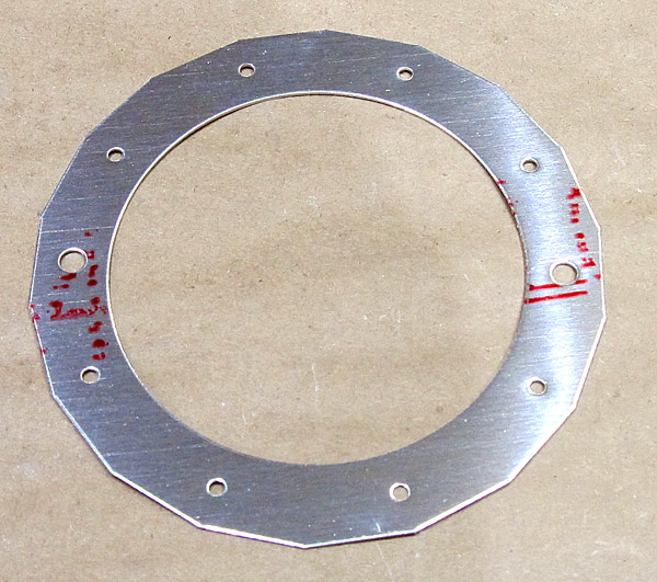
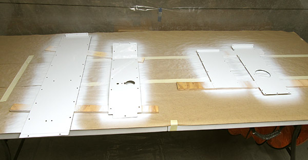
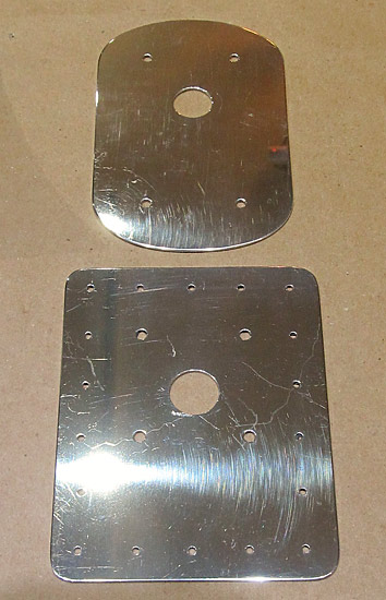
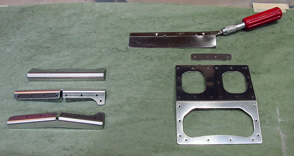
 I am deburring parts listed in Section 42: Miscellanea which are basically access panels that are located in the center of the fuselage cabin interior. |
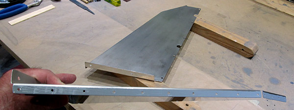
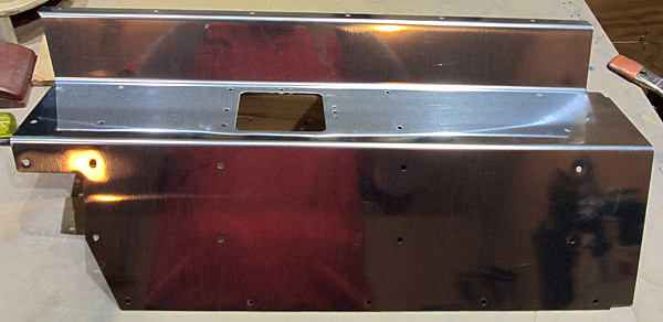
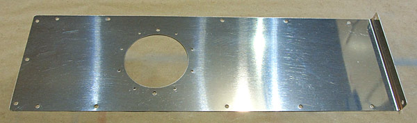
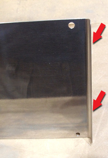
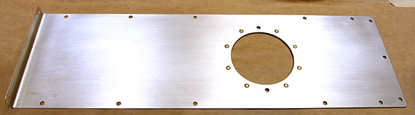
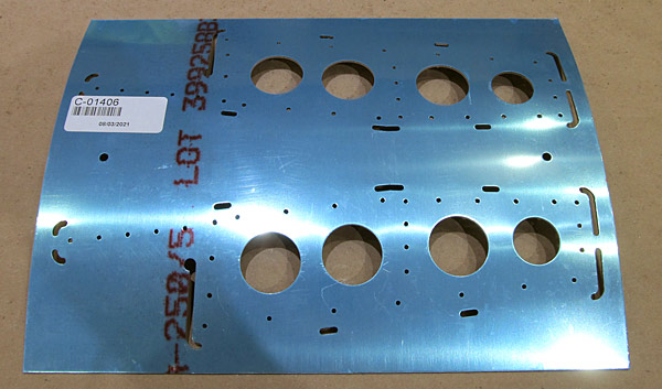
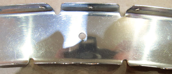
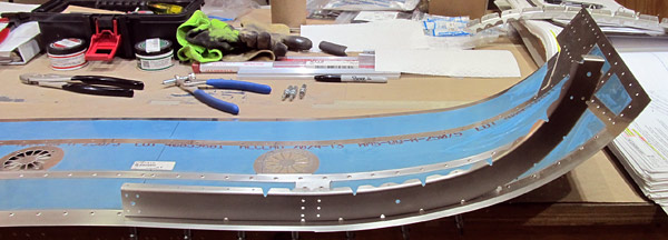
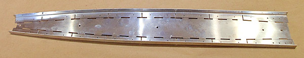
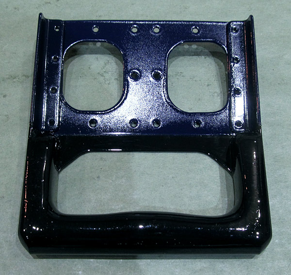
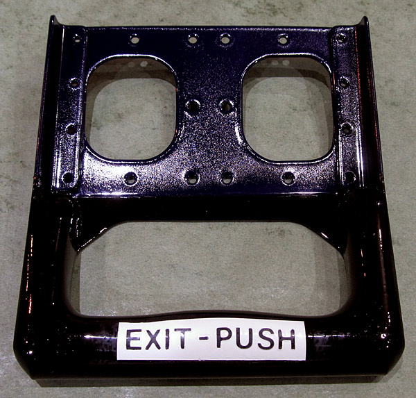
 This is the "door" that separates the baggage compartment from the aft section of the fuselage. |
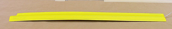
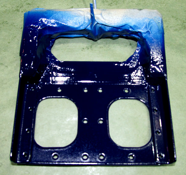
 After the (F-01406F) baggage bulkhead corrugation is painted, a placard to warn passengers as to the experimental nature of this aircraft, will be placed on it to comply with FAA regulations 45.23. |
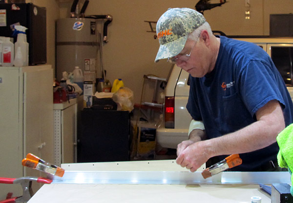 I like to use a hand file to debur the edges of parts first and follow up with sanding or polishing the edges with fine grit sand paper. It also helps to have the part clamped to the bench! |
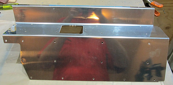
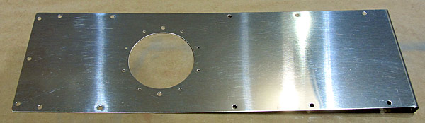
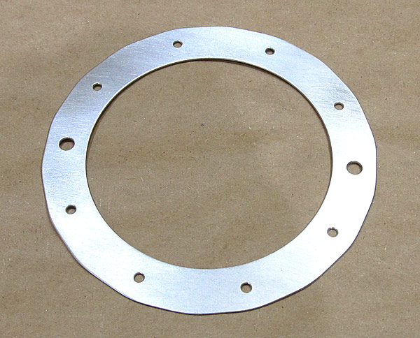
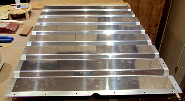
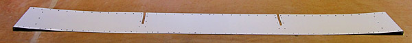
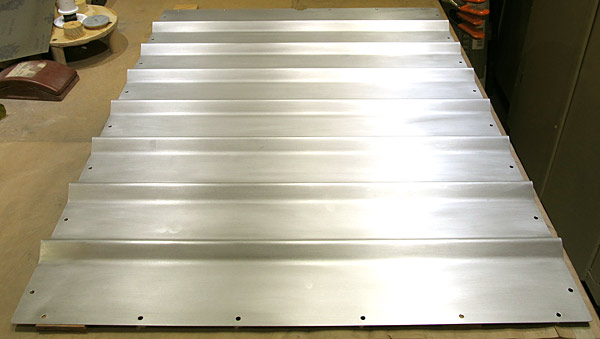 The debur process is done and now I have scuffed the front side with maroon Scotch-Brite™ pads in preparation for painting. |
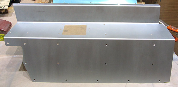
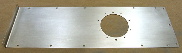
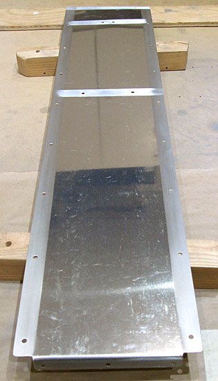
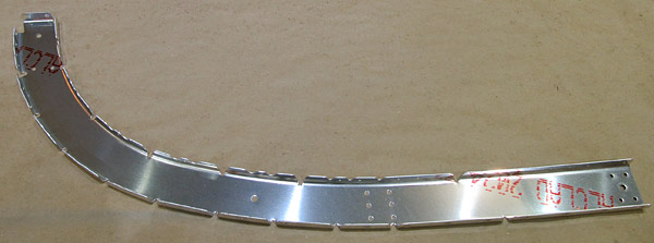
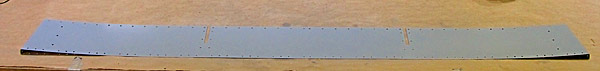
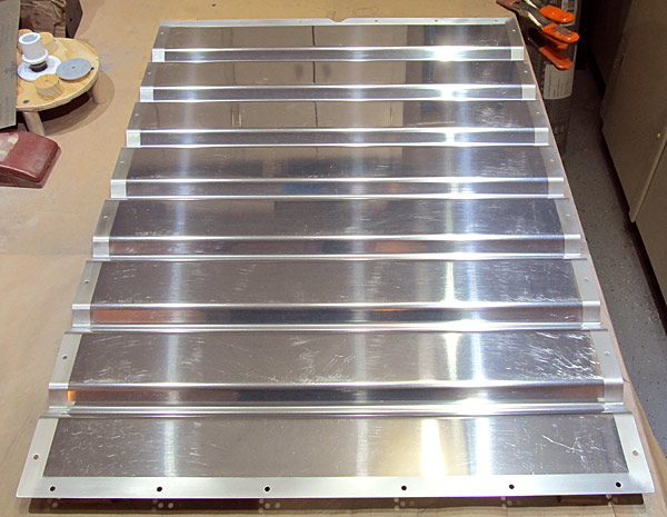 This is the aft side of the (F-01406F) baggage bulkhead corrugation. I am only going to paint the edges and the remainder will be the natural aluminum finish. |
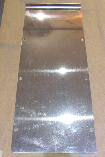
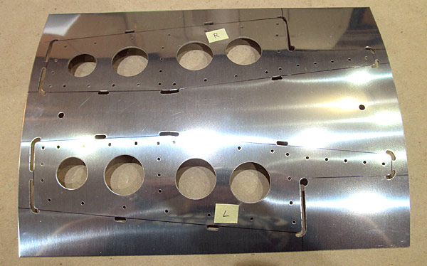
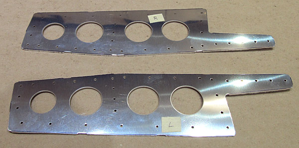
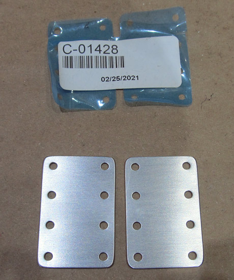
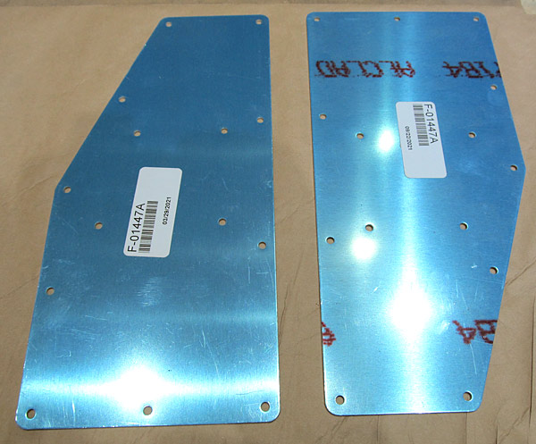 The next parts to be debuured are the (F-01447A) step access covers, there are two of them. These cover the baggage floor section where the aircraft steps are installed. |
 All of the edges of the (F-01447A) step access covers have been deburred and all of the holes have been deburred. |
 I scuffed the (F-01447A) step access floor covers with maroon Scotch-Brite™ pads in preparation for painting. |
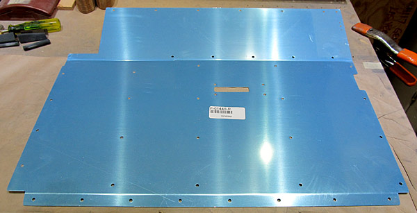
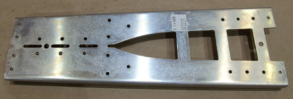
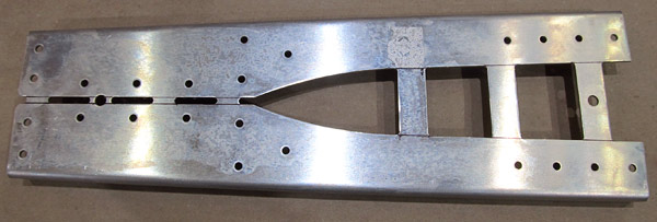
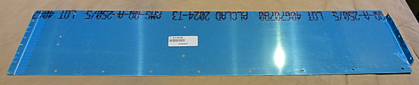 The (F-01446) baggage floor cover is next for deburring. |
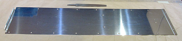 The edges of the (F-01446) baggage floor cover have been deburred and all of the holes have been deburred. |
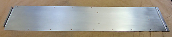 The outer surface of the (F-01446) baggage floor cover has been scuffed with a maroon Scotch-Brite™ pad in preparation for painting. |
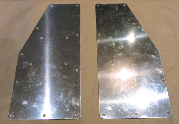
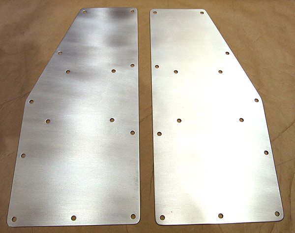
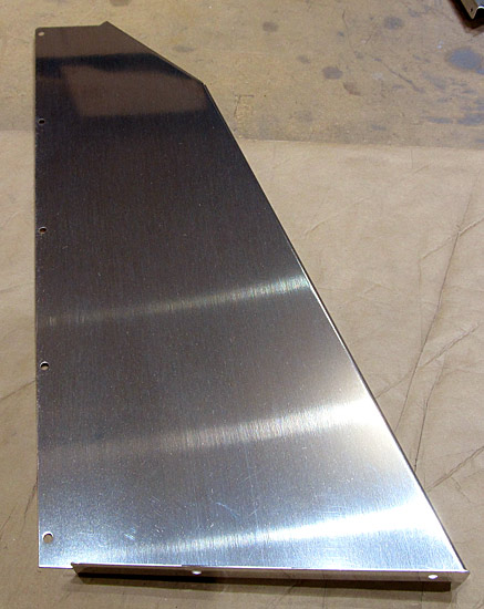
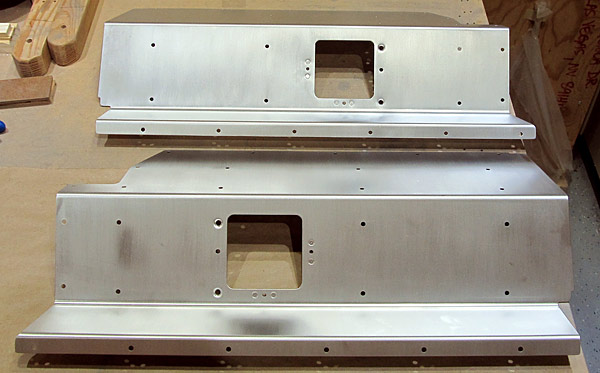
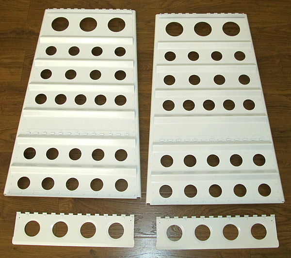
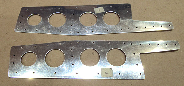
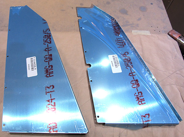 The (F-01445B-L and F-01445B-R) left and right flap motor cover sides are next to be deburred. |
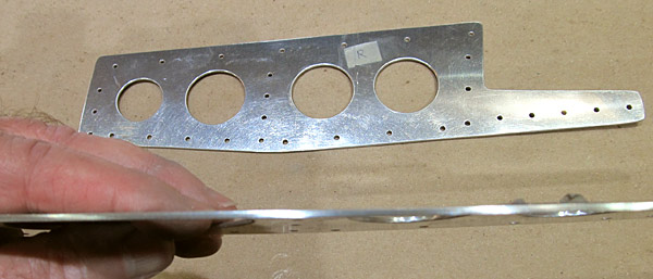
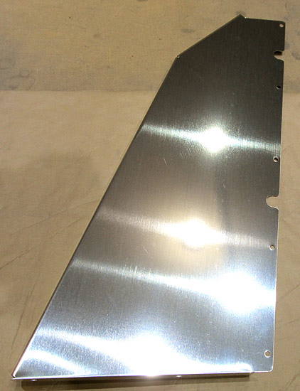 I started deburring the edges of the (F-01445B-R) right flap motor cover. The edges have been deburred here as well as all of the screw holes. |
 I scuffed the outer surface of the (F-01445B-R) flap motor cover with a maroon Scotch-Brite™ pad in preparation for painting. |
 I deburred the edges of the (F-01445B-L) flap motor cover and deburred all of the screw holes. |
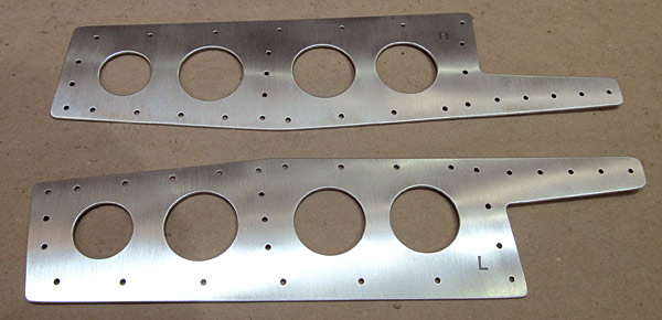
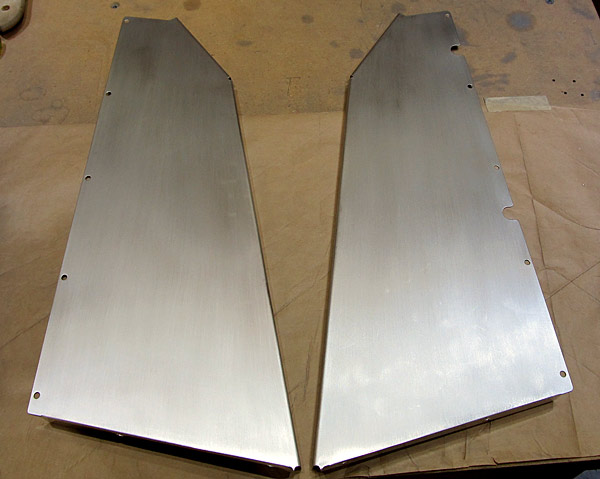 The outer surfaces of the (F-01445B-L and F-01445B-R) left and right flap motor covers with a maroon Scotch-Brite™ pad in preparation for painting. |
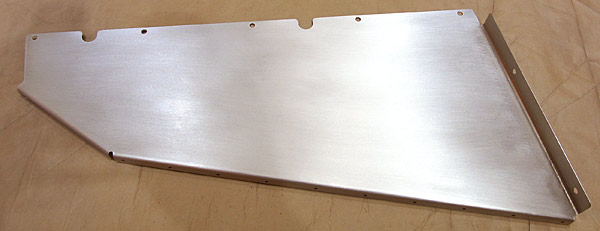
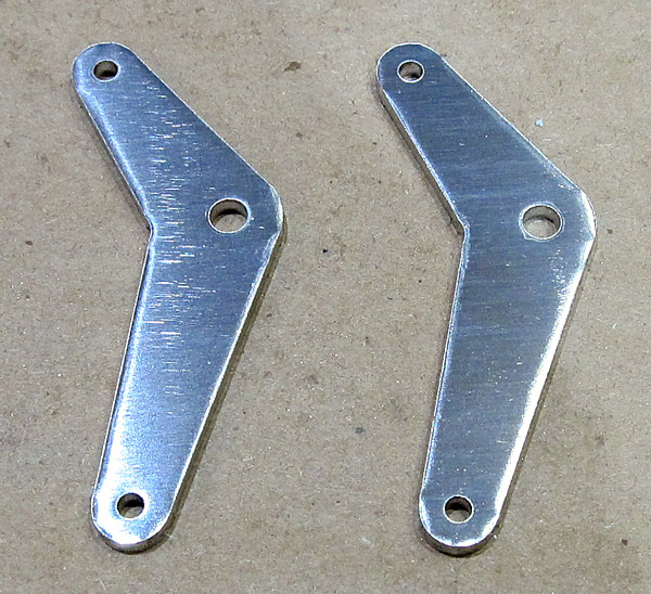
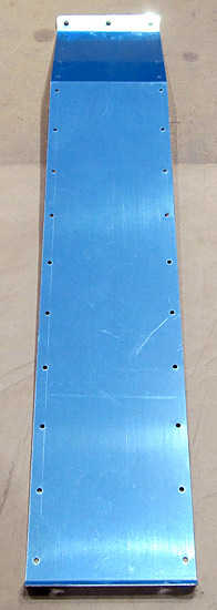 The (F-01445A) front flap motor cover is next to be deburred. |
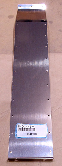 The (F-01445A) front flap motor cover edges have been deburred and all of the screw holes have been deburred. |
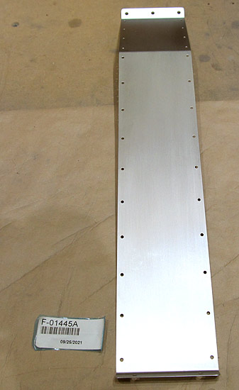 I scuffed the outer surface of the (F-01445A) flap motor cover with a maroon Scotch-Brite™ pad in preparation for painting. |
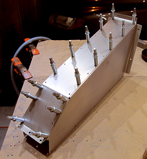
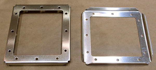
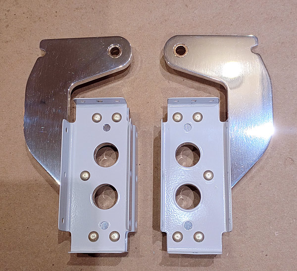
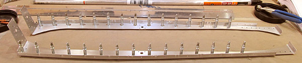
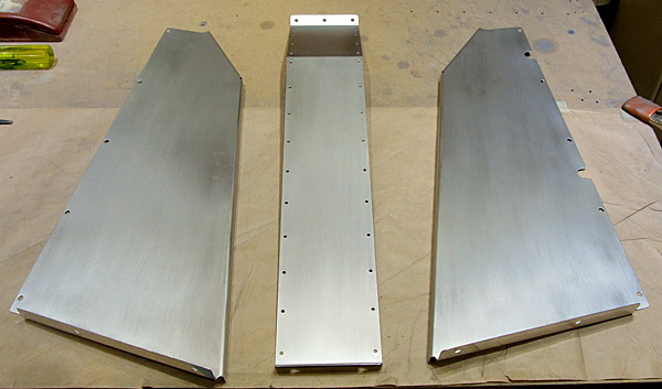 The flap motor cover assembly consists of three pieces, the (F-01445B-L and F-01445B-R) left and right flap motor cover sides, and the (F-01445A) flap motor cover front. |
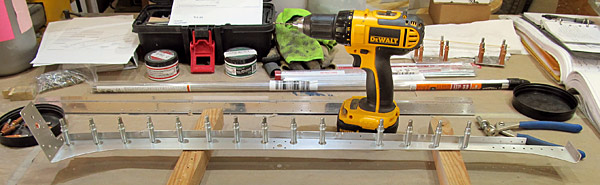
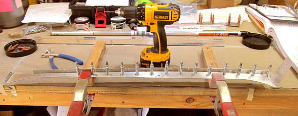
 I clecoed the (F-01445B-L and F-01445B-R) left and right flap motor cover sides to the (F-01445A) flap motor cover front. |
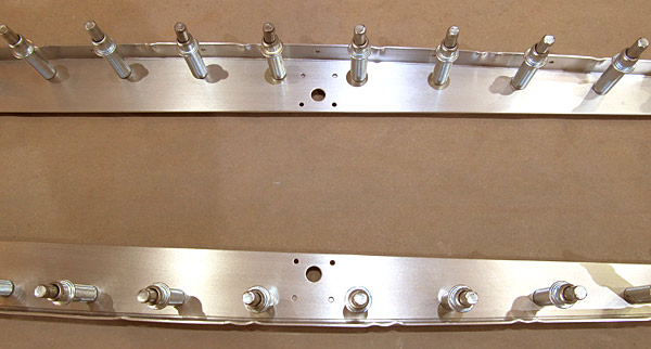
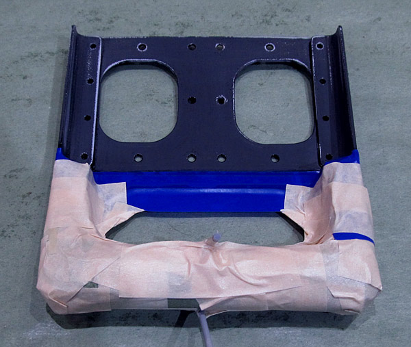
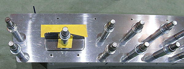
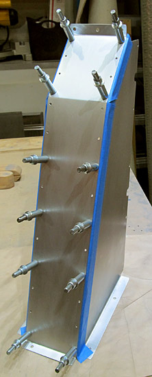 I am placing blue masking tape along the overlapping edges of the flap motor assembly so that when I disassemble the unit I can prime them. |
 I have disassembled the flap cover assembly and will prime the edges with SPI 6610-4 epoxy primer. |
 I just painted the edges with a coat of SPI 6610-4 epoxy primer using a brush, nothing fancy here; it will never be seen! |
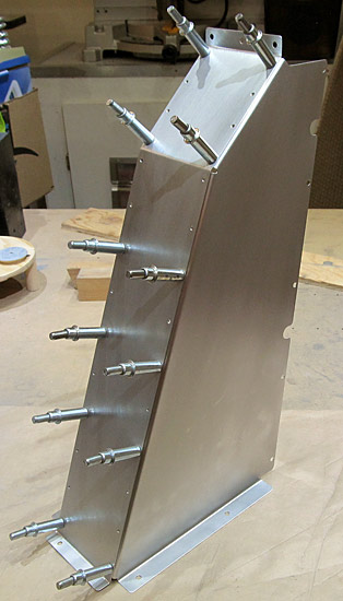
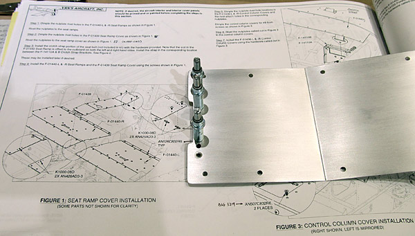
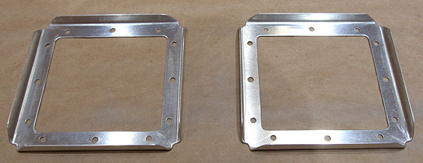
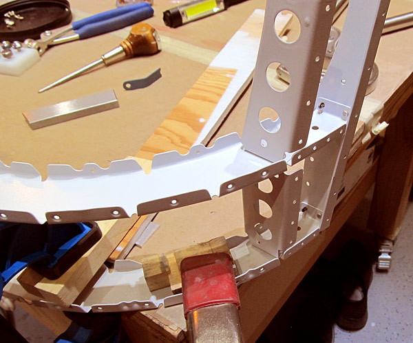
 As per step three, on page 42-03, referencing figure three, the (F-01445B-R, F-01445B-L, and F-01445A) flap motor covers were clecoed together and riveted using AN470AD3-3 rivets set with a rivet gun and tungsten bucking bar. |
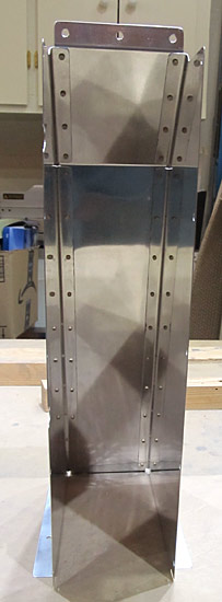 View of the inside of the flap motor cover assembly. |
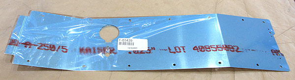 The (F-01439) seat ramp cover is next to be deburred. |
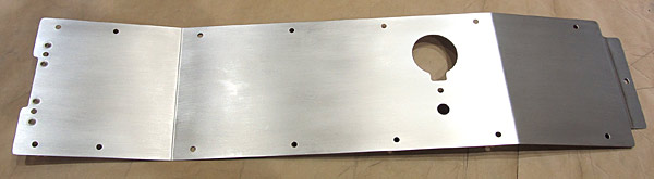
 The (F-01439) seat ramp cover edges have been deburred as were all of the screw holes. |
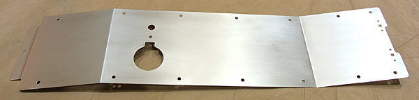 The outer surface of the (F-01439) seat ramp cover was scuffed with a maroon Scotch-Brite™ pad in preparation for painting. |
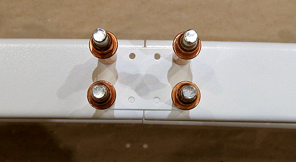
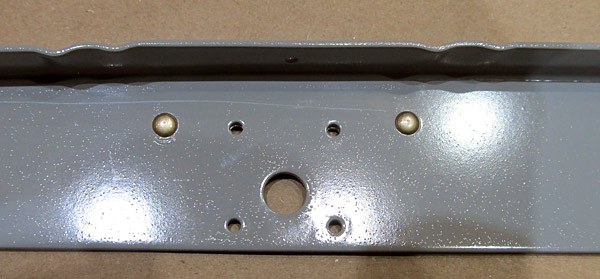
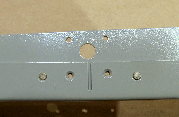
 As per step two, on page 42-02, referencing figure one, four nutplate rivet holes in the (F-01439) seat ramp cover were dimpled to receive AN426AD3-3 rivets. |
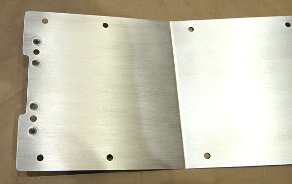 I used our DRDT2 dimple machine to dimple the holes with 3/32" dimple dies. |
 (K1000-08D) nutplates will be installed here. They are pre-dimpled in order to receive the (AN426AD3-3) rivets. |
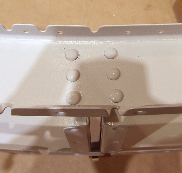
 As per step two, on page 42-02, the (K1000-08D) nutplates were installed using our hand squeezer. |
 Just a closer view. |
 View from the back side of the (F-01439) seat ramp cover nutplate installation. |
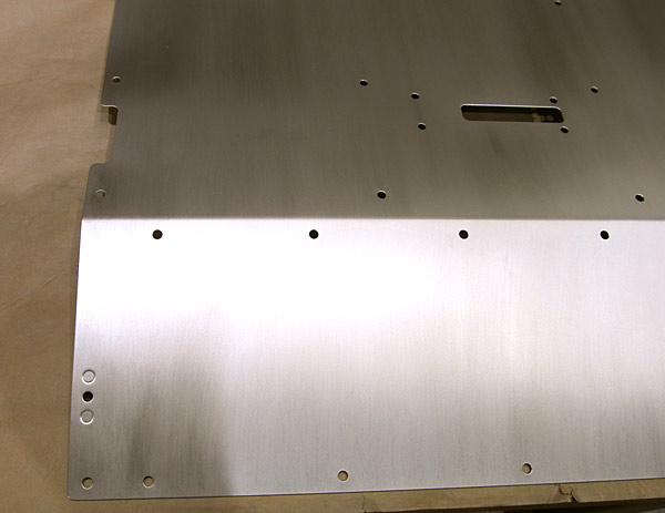
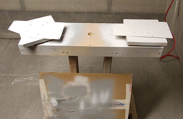
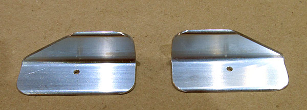
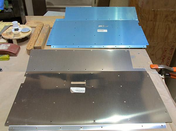 There are two seat ramps, (F-01440-L and F-01440-R). They are the at base of the front seats. |
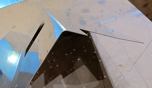
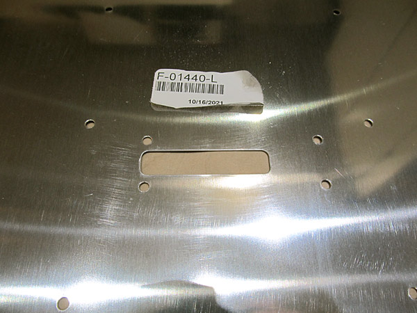 Since the crotch strap is passed through this slot, I made sure that the edges of the slot were rounded over so as to not have a point where abrasion could occur. |
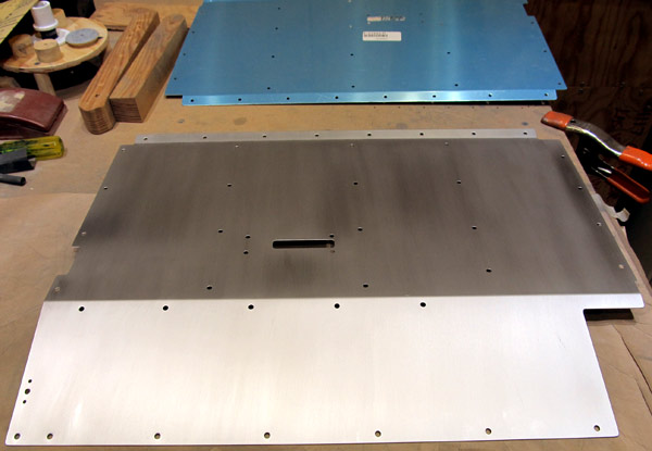 I scuffed the outer surface of the (F-01440-L) left seat ramp with a maroon Scotch-Brite™ pad in preparation for painting. |
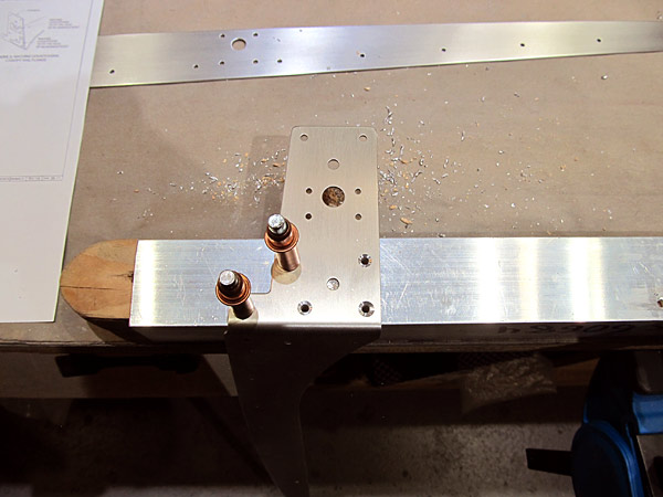
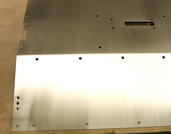 As per step one, on page 42-02, referencing figure one, the nutplate rivet holes in the (F-01440-L) left seat ramp were dimpled to accept AN426AD3-3 rivets. |
 The K1000-08D nutplate was riveted to the (F-01440-L) left seat ramp with AN426AD3-3 rivets set with our hand squeezer. |
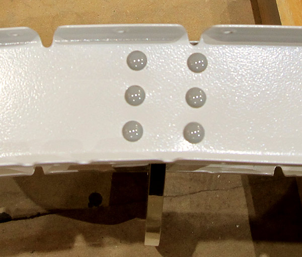
 Top view of nutplate rivets set on the (F-01440-L) left seat ramp. |
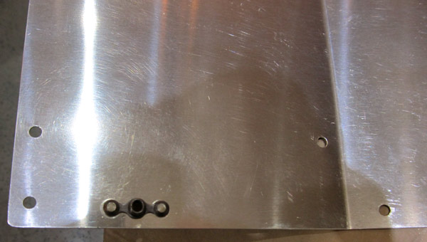 View of nutplate on the back side of the (F-01440-L) left seat ramp. |
 Next, on to the deburring process of the (F-01440-R) right seat ramp. Just like the left seat ramp, this panel is at the base of the seat on the right side of the aircraft. |
 The edges of the (F-01440-R) right seat ramp and all of the screw holes were deburred. |
 The edges were polished on this (F-01440-R) right seat ramp, (as they are on all of my deburring operations), using fine grit sandpaper. |
 I scuffed the outer surface of the (F-01440-R) right seat ramp with maroon and gray Scotch-Brite™ pads and washed all surfaces with acetone in preparation for painting. |
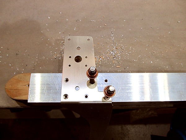
 As per step one, on page 42-02, referencing figure one, I dimpled the nutplate holes in the (F-01440-R) right seat ramp in order to receive AN426AD3-3 rivets using 3/32" dimple dies set with our DRDT2 dimple machine. |
 As per step one, on page 42-02, referencing figure one, I riveted the K1000-08D nutplates to the (F-01440-R) right seat ramp with AN426AD3-3 rivets using our hand squeezer. |
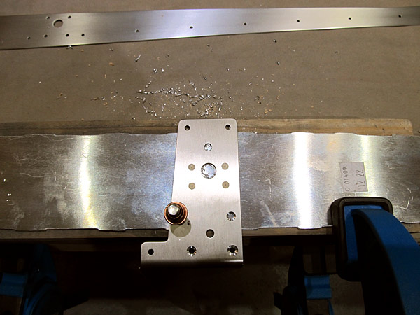
 Here is the view of the riveted K1000-08D nutplate on the back side of the (F-01440-R) right seat ramp. |
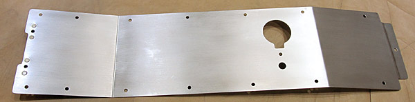
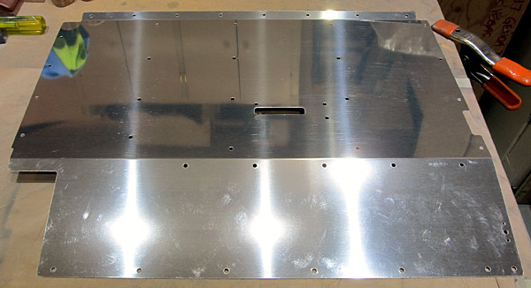
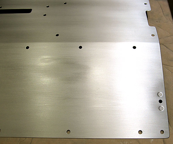
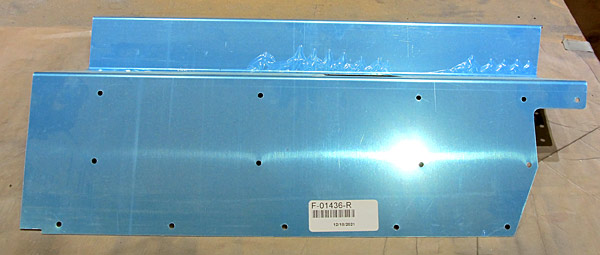
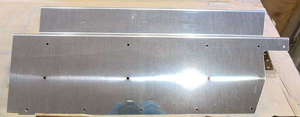
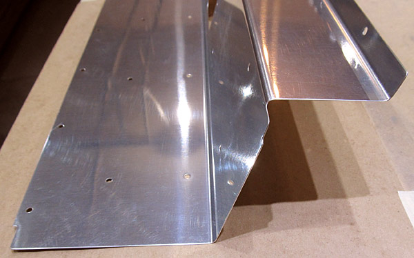
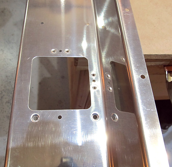
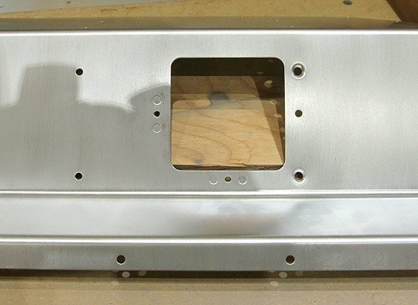
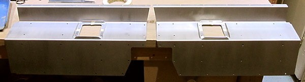
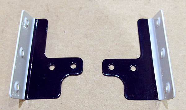
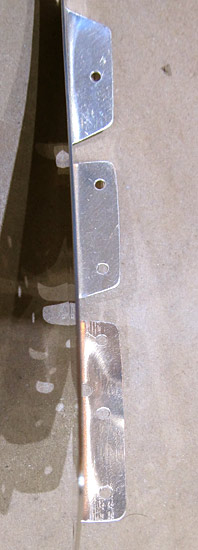
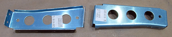
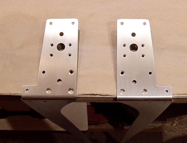
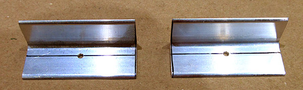
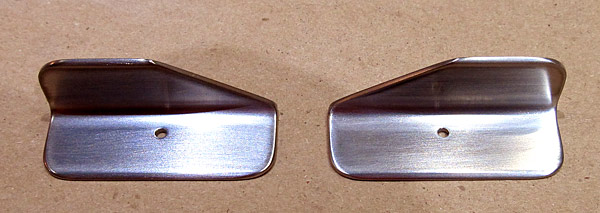
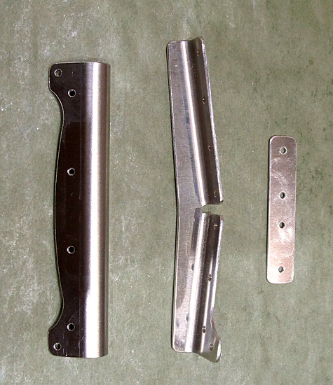
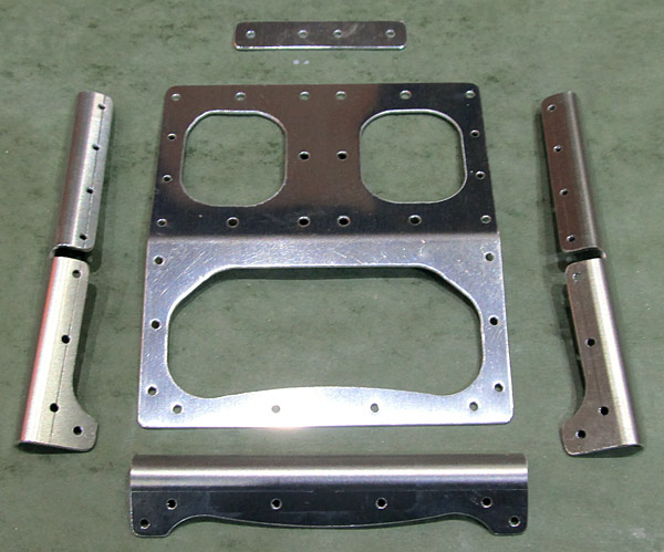
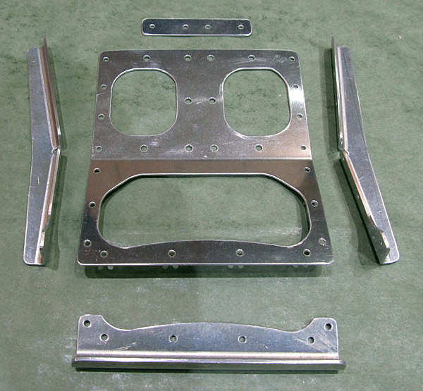
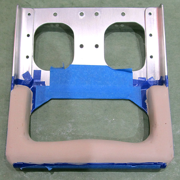
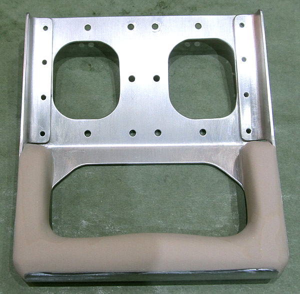
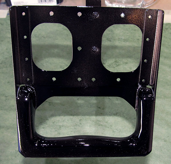
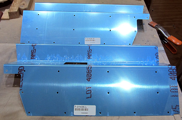 These are the (F-01436-L and F-01436-R) left and right control column covers. They are next for deburring. |
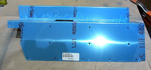 I am starting on the (F-01436-L) left control column cover. |
 I deburred the edges and all of the holes in the (F-01436-L) control column cover using a file. |
 After the file work is done I like to polish the edges of the pieces with fine grit sandpaper. I usually start with 220 grit sandpaper and finish with 600 grit. |
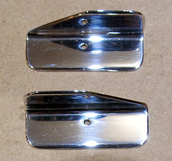
 Nice! |
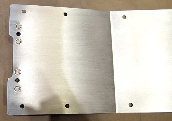
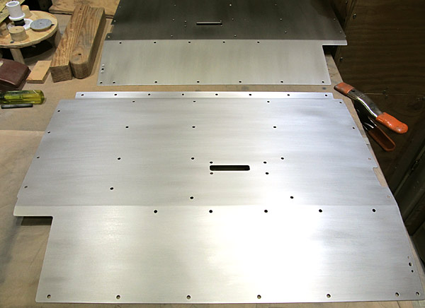
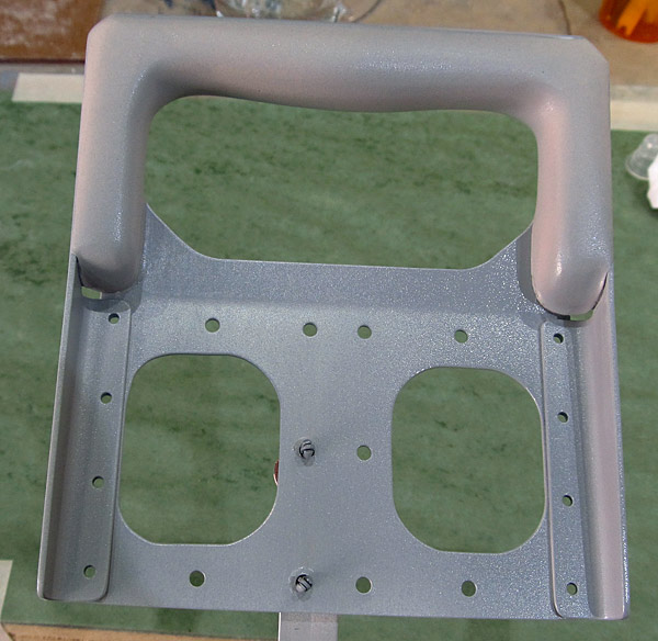
 I scuffed the outer surface of the (F-01436-L) left control column cover with maroon and gray Scotch-Brite™ pads in preparation for painting. |
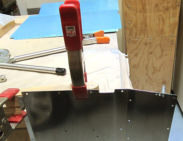
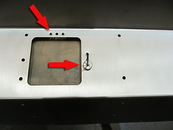
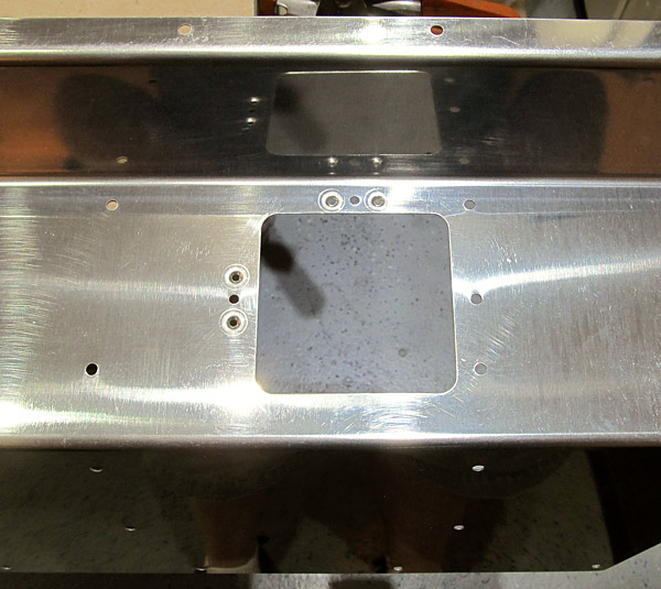
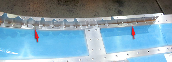
 This is the part where I am a little embarassed about....there are four holes that need to be dimpled in order to install nutplates. The "throw" on our hand squeezer is 3 inches and it will not reach the two holes located at the back of the (F-01436-L) left control column cover because of the bend (almost 90°) in the piece and I can't get it into the opening to get at the holes.....what am I going to do? |
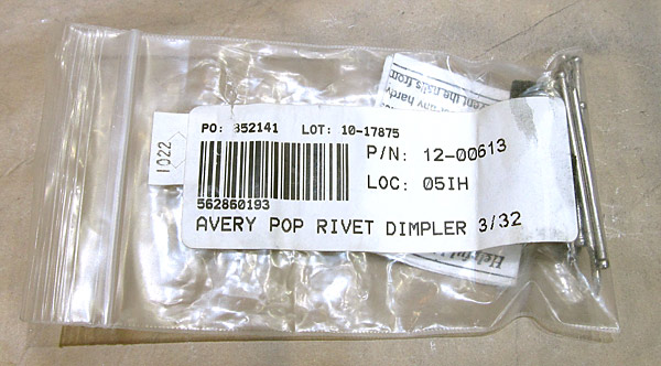
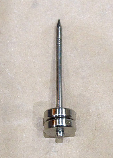 The Avery pop rivet dimpler has a male and female 3/32" dimple die set and uses a hardware nail (4D I think) as the mandrel that an ordinary pop rivet gun will use to make the dimple. |
 You just slip the female die and mandrel through the bottom of the metal that needs to be dimpled and the male dimple die will be placed over the mandrel on the opposite side. |
 Make sure everything is snug. |
 Now on the other side the male dimple die gets placed onto the nail mandrel. |
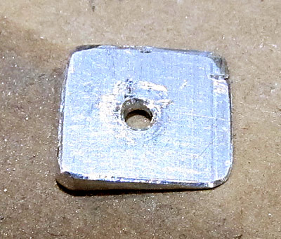
 As you can see, the dimples turn out nice. |
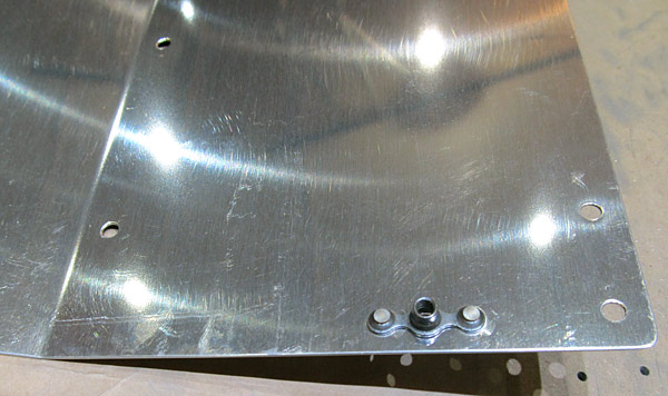
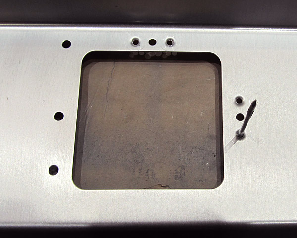
 As per step five, on page 42-02, referencing figure three, I dimpled the four rivet holes on the (F-01436-L) left control column cover that will receive AN426AD3-3 rivets using the Avery 3/32" pop rivet gun dimple tool. |
 Now the next hurdle....how do I dimple the #8 screw holes? I don't have a #8 pop rivet gun dimple tool, (I still haven't figured it out that I have a 1.5" yoke for the hand squeezer) that will easily do the job. |
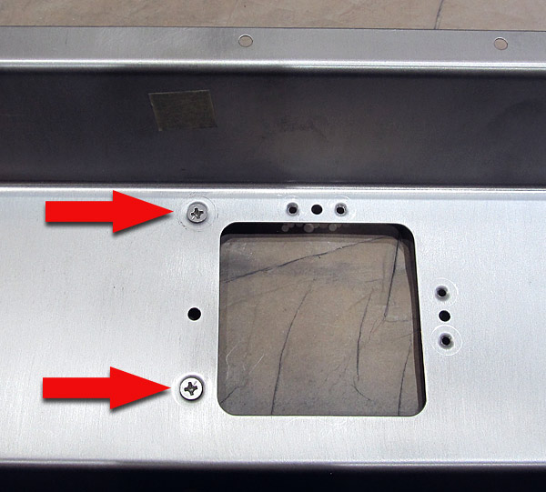
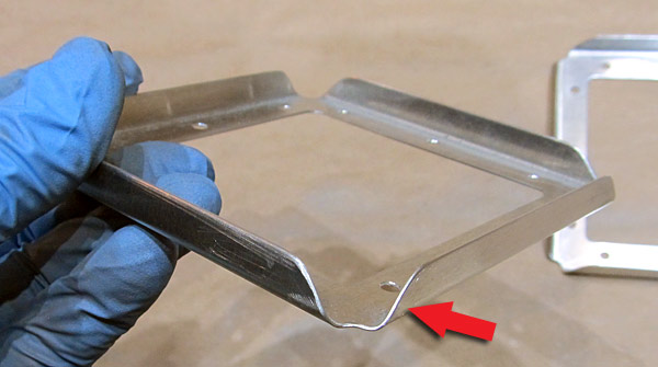
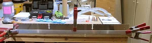
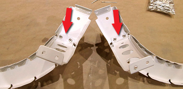
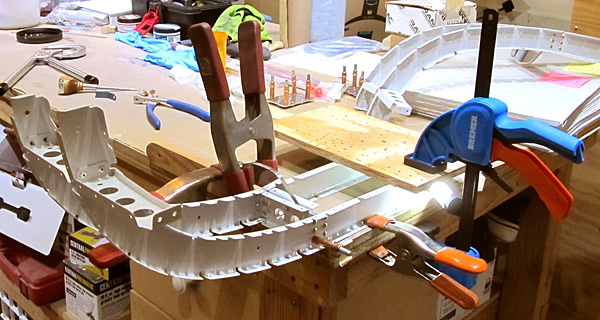
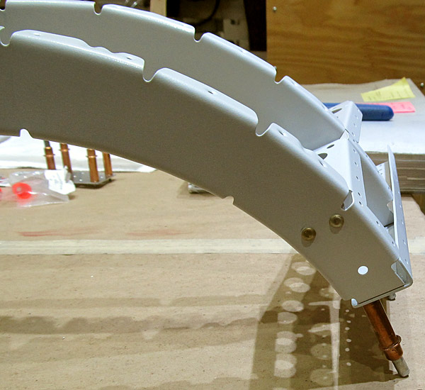
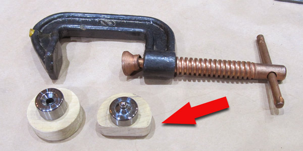 This is the apparatus that I constructed in order to dimple the #8 screw holes that are in the hard to reach areas of the (F-01436-L) left control column cover. |
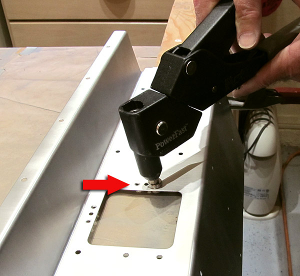
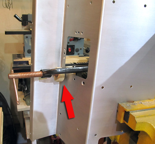 As per step five, on page 42-02, referencing figure three, I dimpled the remaining #8 screw hole on the (F-01436-L) left control coulmn cover with the "C" Clamp device. |
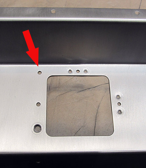
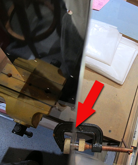 Here is what it looks like when viewing from above, you can also see why I made the one wood dimple die holder semi-circular because the edge does get a little close to the bend in the metal of the (F-01436-L) left control coulmn cover. |
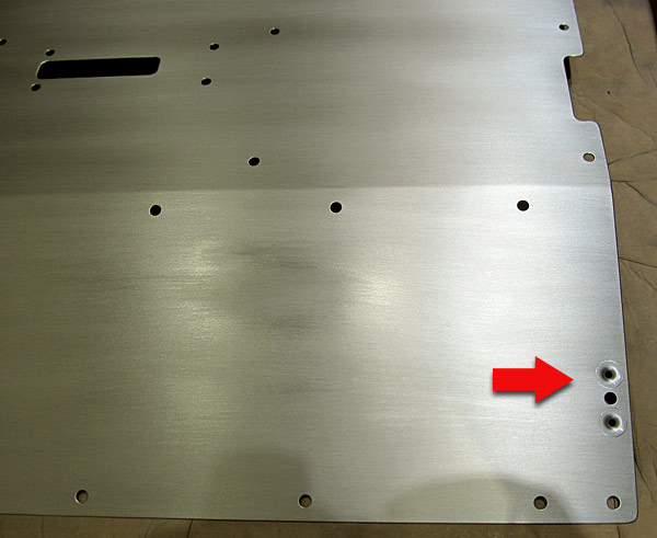
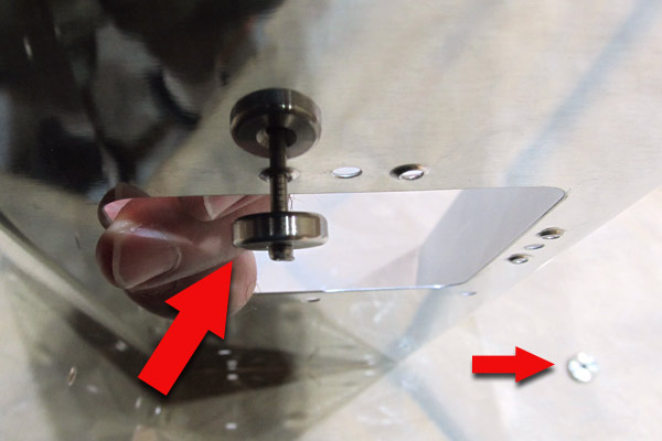
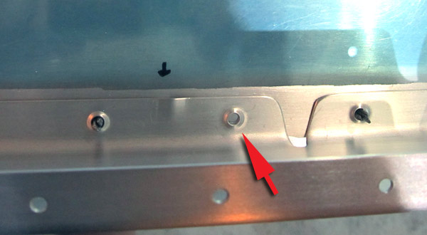
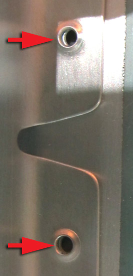
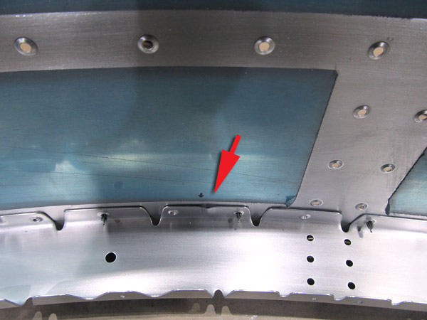
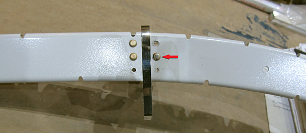
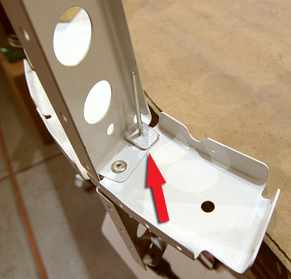
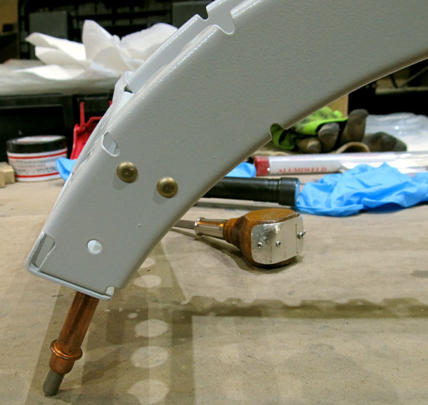
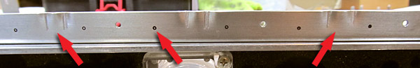
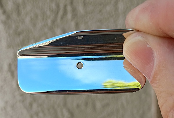
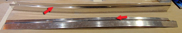
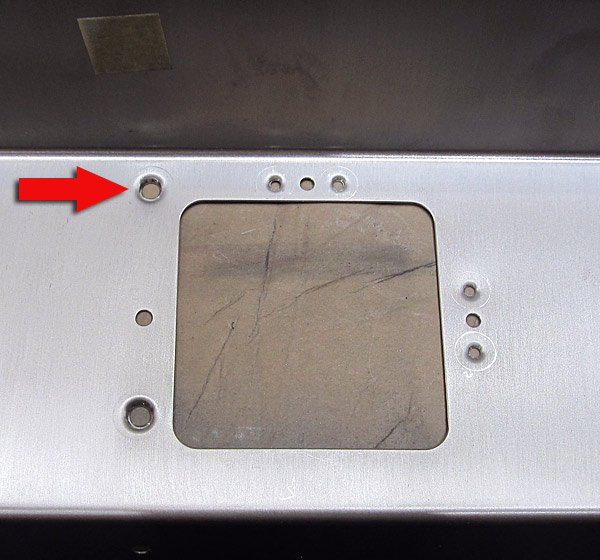 The "C" Clamp device did a nice job, the arrow points to the hole dimpled by the device and the hole at the bottom was done with our DRDT2 dimple machine. They are virtually the same in appearance! |
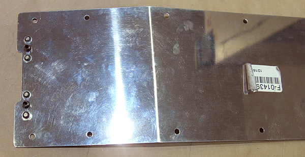
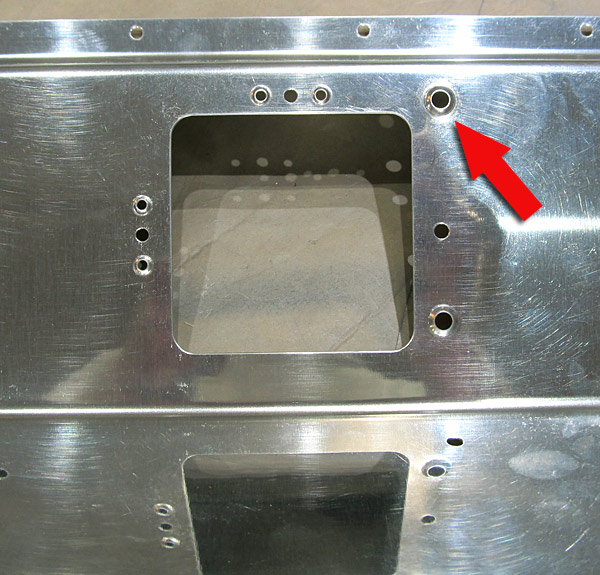 Here is what the "C" Clamp dimple looks like on the other side. |
 The #8 screws sit in the dimples nicely! |
 Now it's time to debur the edges on the (F-01436-R) right control column cover. |
 Back to the edge deburring.... |
 After the file work is done I like to polish the edges of the pieces with fine grit sandpaper. I usually start with 220 grit sandpaper and finish with 600 grit. |
 Nice! |
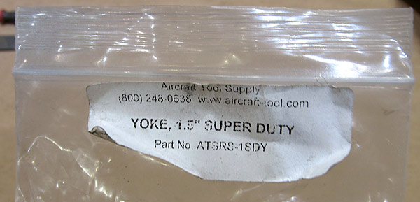 This is the 1.5" yoke for our hand held squeezer, I've had it for a long time but never needed to use it very much. |
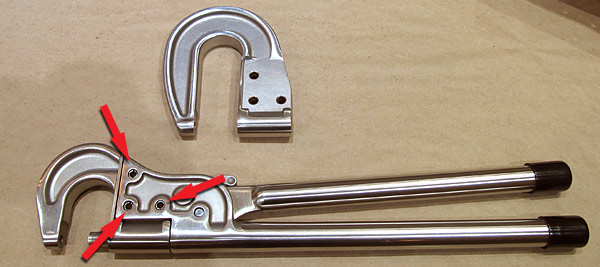 To change the yokes all you have to do is use a hammer and punch to remove the three roll pins and switch the yokes out. |
 The hand squeezer now has a 1.5" yoke installed! |
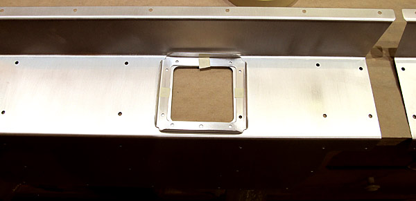
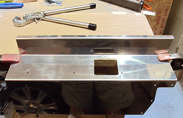 As per step five, on page 42-02, referencing figure three, I dimpled the nutplate holes in the (F-01436-R) right control column cover using our hand rivet squeezer equipped with a 1.5" yoke. |
 The dimpling process went a lot faster on this (F-01436-R) right control column cover because I changed over to the 1.5" yoke. There is plenty of room to get the yoke into the space through the rectangular opening. |
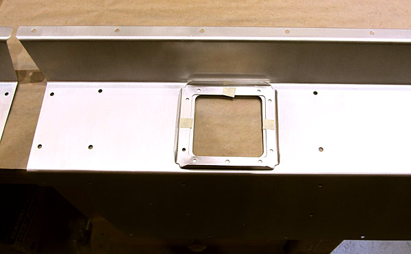
 As per step five, on page 42-02, referencing figure three, I dimpled the #8 screw holes in the (F-01436-R) right control column cover using the hand rivet squeezer equipped with #8 screw dimple dies. |
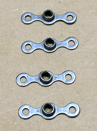 These four K1000-06 nutplates need to be dimpled. I will need to use a small diameter female 3/32" dimple die here because a regular sized one might be block by the center screw receiver post. |
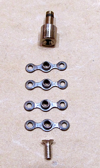 As per step five, on page 42-02, referencing figure three, the four K1000-06 nutplates were dimpled using our DRDT2 dimple machine equipped with one 3/32" male substructure dimple die set and one 3/32" small diameter female dimple die set. |
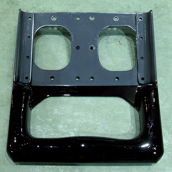
 As per step six, on page 42-02, referencing figure three, the K1000-06 nutplates were riveted to the (F-01436-L and F-01436-R) left and right control column covers with AN426AD3-3 rivets using our hand rivet squeezer. |
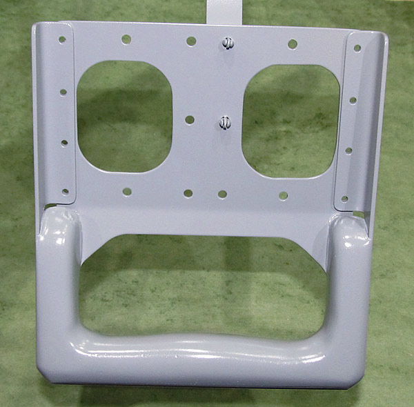
 I scuffed the (F-01436-R) right control column cover with maroon and gray Scotch-Brite™ pads in preparation for painting. |
 Here is a better picture of the scuffed (F-01436-R) right control column cover. Usually I do a quick wash of acetone to clean up the fine dust particles after the scuffing process. Later, just before painting, the piece will get a soap and water washing and degreased. |
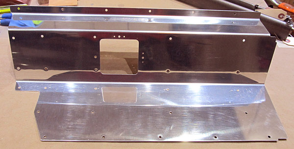
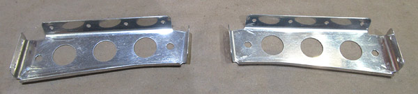
 Both of the (F-01436-L and F-01436-R) left and right control column covers have been scuffed. |
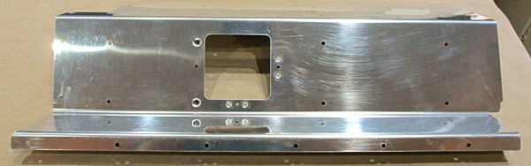
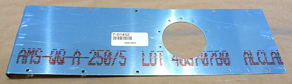 The (F-01452) aft tunnel cover is next in line for deburring. |
 I deburred the edges and all of the holes of the (F-01452) aft tunnel cover. |
 The edges of the (F-01452) aft tunnel cover were sanded and polished with various grits of sandpaper, starting with 220 grit and ending with 600 grit....I know, lots of extra work... |
 I scuffed the (F-01452) aft tunnel cover with maroon and gray Scotch-Brite™ pads in preparation for painting. |
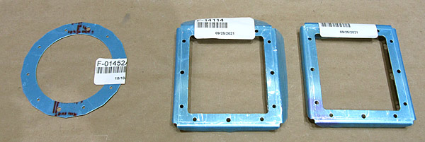 There are three small pieces that will be riveted in place on the different panels, the two (F-14114) control stick doublers, and the (F-01452A) aft tunnel cover doubler. |
 This is the (F-01452A) aft tunnel cover doubler. |
 I deburred the edges and all of the holes of the (F-01452A) aft tunnel cover doubler and scuffed all of the surfaces with maroon and gray Scotch-Brite™ pads in preparation for painting. |
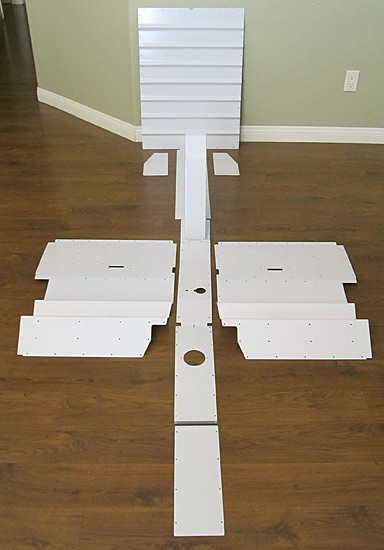
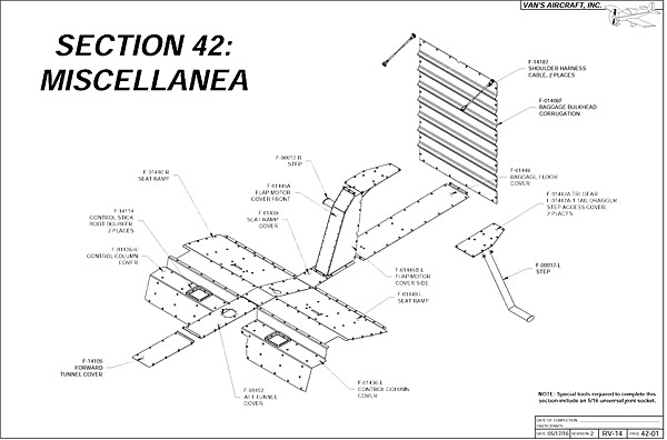 I just wanted to recap that I am in Section 42 called Miscellanea which is basically all of the access covers in the interior of the aircraft cabin plus the outside steps. |
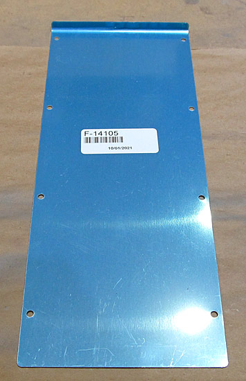 This is the (F-14105) forward tunnel cover. I start out with a file and debur the edges. |
 After I debur the edges I like to "polish" them with fine grit sandpaper. |
 All of the holes are deburred in the (F-14105) forward tunnel cover. |
 I scuffed the outer surface of the (F-14105) foward tunnel cover with maroon Scotch-Brite™ pads in preparation for priming. |
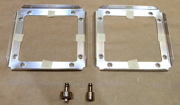
 These are the two (F-14114) control stick boot doublers. |
 The deburring process begins again starting with deburring the edges with a small file and all of the holes were deburred. |
 After deburring the edges and deburring all of the holes of the (F-14114) control stick boot doublers I polished the edges with fine grit sandpaper. |
 The surfaces of the two (F-14114) control stick boot doublers were scuffed with maroon Scotch-Brite™ pads in preparation for priming. |
 As per step one, on page 42-07, and referencing figure one, the instructions mention that the holes in the (F-14114) control stick boot doublers need to be dimpled on the bottom sides so that the stick boots (not included in the kit) can be attached with AACQ 4-3 rivets (also not included in the kit). The question is, which holes need to be dimpled? I set up the (F-01436-L and F-01436-R) left and right control column covers onto the bench and then placed the two (F-14114) control stick boot doublers into position to figure this out. |
 Remember that in step six, on page 42-02, and referencing figure three, nutplates were installed onto the (F-01436-L and F-01436-R) left and right control column covers so these holes had to remain open. Knowing that the (F-14114) control stick boot doublers were held in place by three MS35206-228 screws and these three holes had to remain open, placing the control stick boot doublers in the proper orientation is important. |
 This is the left control column cover. |
 As per step one, on page 42-07, referencing figure one, the two (F-14114) control stick boot doublers were dimpled in the appropriate holes, and from the bottom side, in order to receive (AACQ 4-3) rivets. |
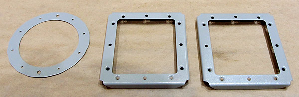 I primed the (F-01452A) aft tunnel cover doubler and the two (F-14114) control stick boot doublers with SPI (Southern Polyurethanes, Inc) 6610-4 gray epoxy primer. |
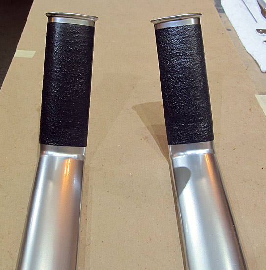
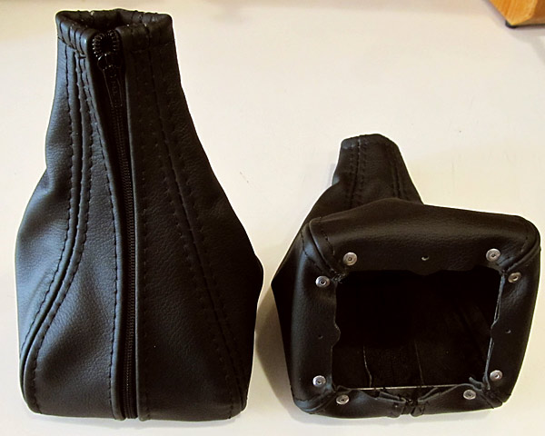 I ordered stick covers from Classic Aero Designs, located in Albany, Oregon and ironically if I had known that their stick covers came with the (F-14114) control stick boot doublers already attached, I would not have had to do all of the previous work on the stick boot doublers that came with the kit from Van's Aircraft. |
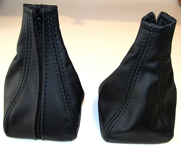 These stick covers are really nice and they are made of FAA approved leather. These are Orion/Raven colored, but you can order different colors from them. |
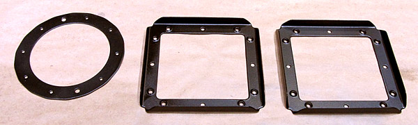
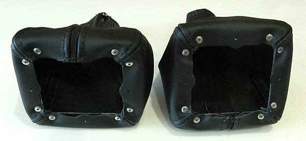 You can see the AACQ 4-3 rivets that hold the leather to the (F-14114) control stick boot doublers. |
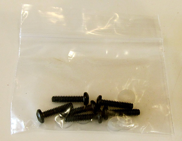 The MS35206-228 screws are included with the stick covers. |
 I painted the two (F-14114) control stick boot doublers and the (F-01452A) aft tunnel cover with Krylon Cover Maxx gloss black paint. |
 As per step one, on page 42-03 of the builder's manual and referencing figure one, I riveted the (F-01452A) aft tunnel cover doubler to the (F-01452) aft tunnel cover setting AN470AD3-3 rivets with our hand held squeezer. |
|
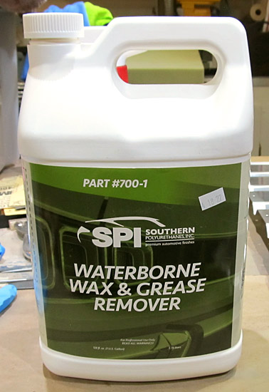 When I clean the bare metal parts in preparation for priming, I usually clean them with soap and water first and then use this SPI (Southern Polyurethanes, Inc.) waterborne wax and grease remover. |
 I cleaned and degreased the (F-01406F) baggage bulkhead corrugation with the SPI waterborne wax and grease remover in preparation for priming. |
 I cleaned and degreased the (F-01446) baggage floor cover with the SPI waterborne wax and grease remover in preparation for priming. |
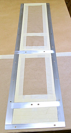 I masked the centers of the (F-01446) baggage floor cover and also the (F-01406F) baggage bulkhead corrugation, in order to expose the edges, in preparation for priming. |
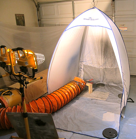
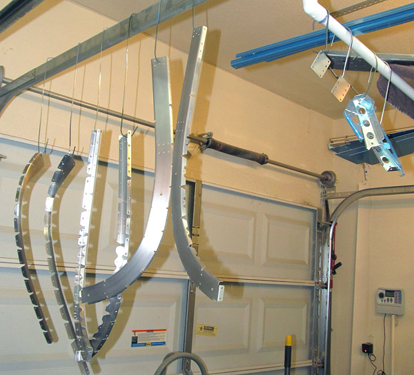
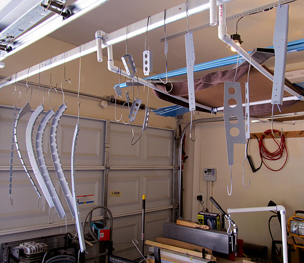
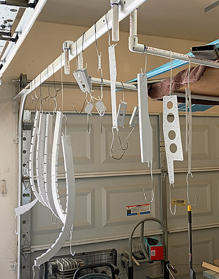
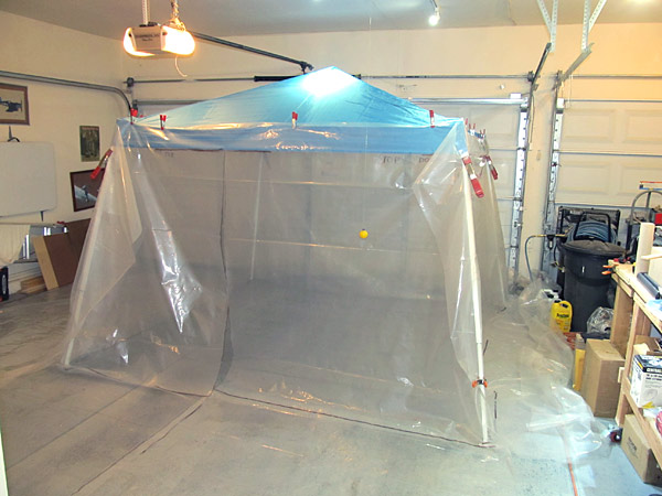 This is my large paint booth that I use in the garage to paint some of the medium sized parts. |
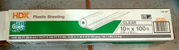 I clamp 6 mil plastic sheeting, that I bought from Home Depot, to cover the sides and bottoms in order to contain the overspray of paint. |
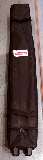 When I am done using the paint booth, I fold it up and it is stored in the wheeled storage bag that was included in the pop-up canopy kit. |
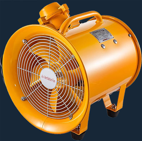 To exhaust the booth when I am painting, I use a Vevor 12 inch explosion proof fan. |
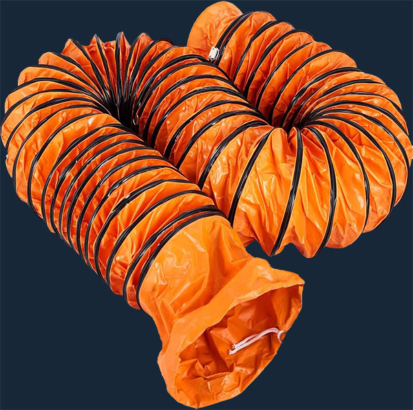 This is the 12 inch x 25 foot Vevor PVC flexible duct hosing that I am using to vent between the paint booth and the exhaust fan. |
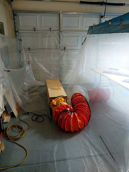 Here you can see the exhaust set up... |
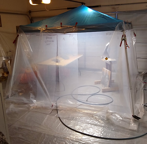 Here is the booth in use, I use a light unit from Harbor Freight to light the booth. |
 I primed the following parts with SPI (Southern Polyurethanes, Inc.) 6610-4 gray epoxy primer: |
 (F-01406F) front side of baggage bulkhead corrugation |
 All of the parts were sanded and scuffed before painting with Stewart Systems Ekocrylic waterborne E5301 smoke gray. |
 The seat back brace assemblies and the seatback assemblies were painted with Stewart Systems waterborne Ekocrylic E5301 smoke gray paint. |
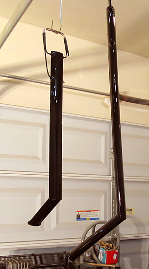
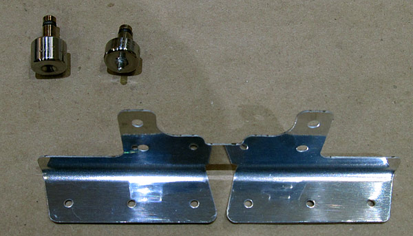
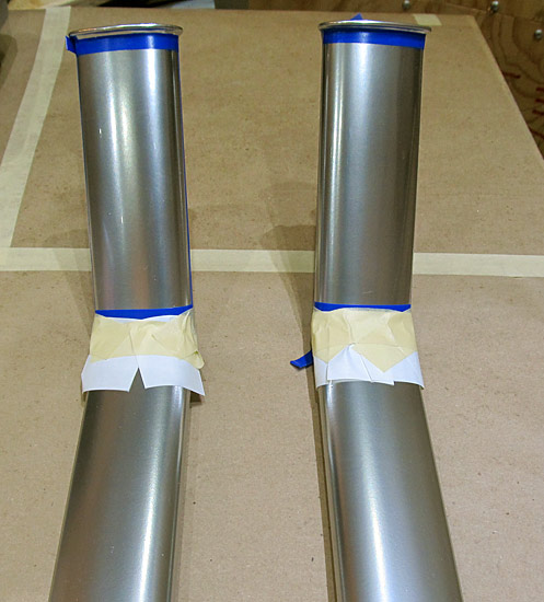
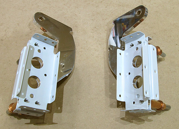
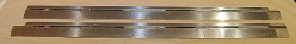
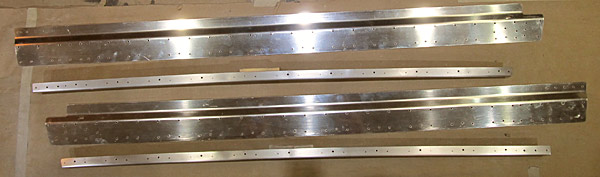
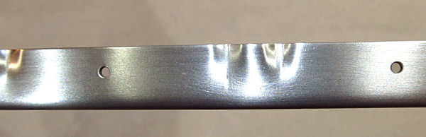
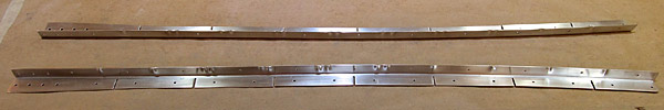
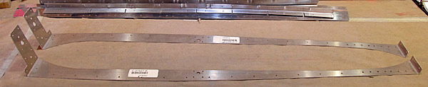
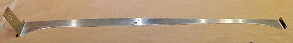
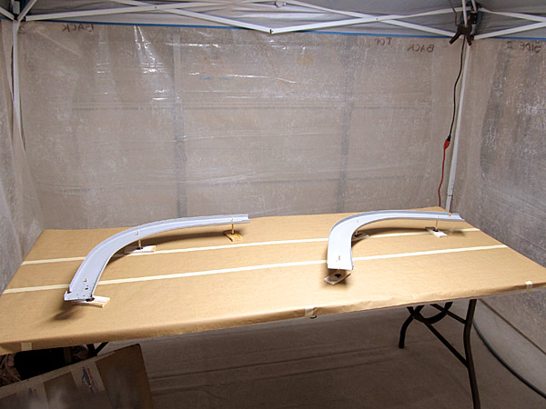
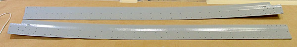
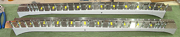
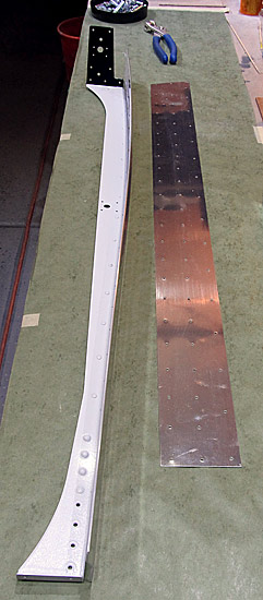
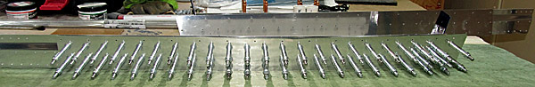
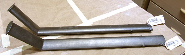 The (F-00017-L and F-00017-R) left and right steps are made of 4130 chromium molybdenum alloy steel. They are very hard and strong but the texture is grainy and rough. I want to sand and smooth them out in preparation for painting. I am using silicon carbide sandpaper so that I do not get dissimilar metal contamination. I am starting out with 150 grit sandpaper. |
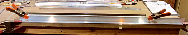
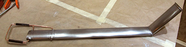 I sanded the (F-00017-L) left step first, starting out with 150 grit silicon carbide sandpaper and working up through the grits to at least 400 grit so that when I apply the primer and topcoat paints I'll get a super smooth finish....the idea is not to have to use any heavy fillers as well. I also fashioned a heavy copper wire rod to hold the step and manuever it as I paint it in the paint booth. |
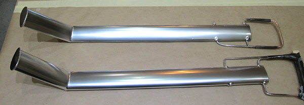
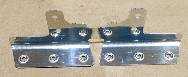
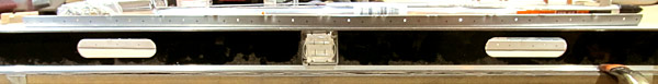
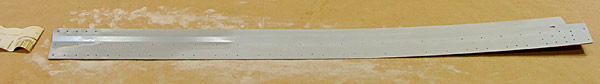
 Now to sand the (F-00017-R) right step. |
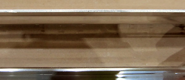
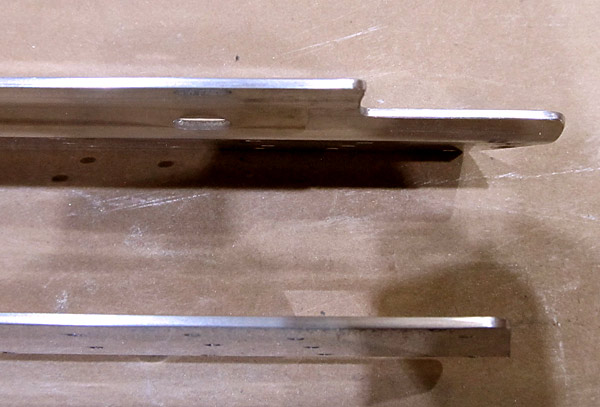
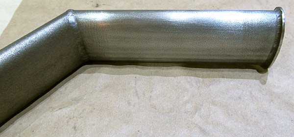 If you look closely, you can see the textured surface of the step, I still need to get this one a little smoother for painting. |
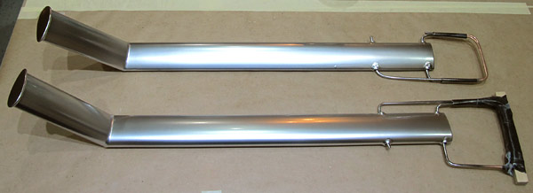
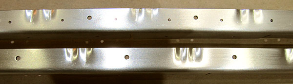
 I finished sanding the (F-00017-R) right step. Now it is time to clean the steps with soap and water and then wax and degrease them with the degreaser. |
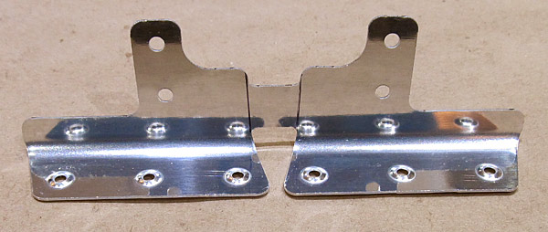
 I washed and degreased the two steps with SPI (Southern Polyurethanes, Inc.) 700-1 waterborne wax and grease remover. |
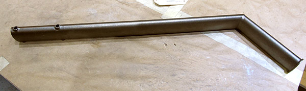
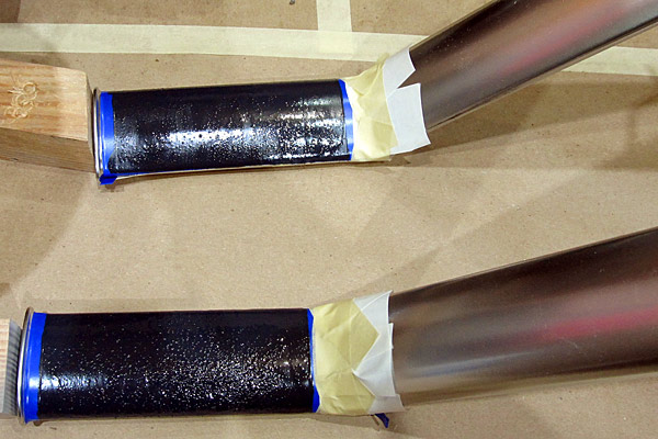
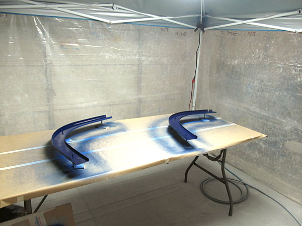
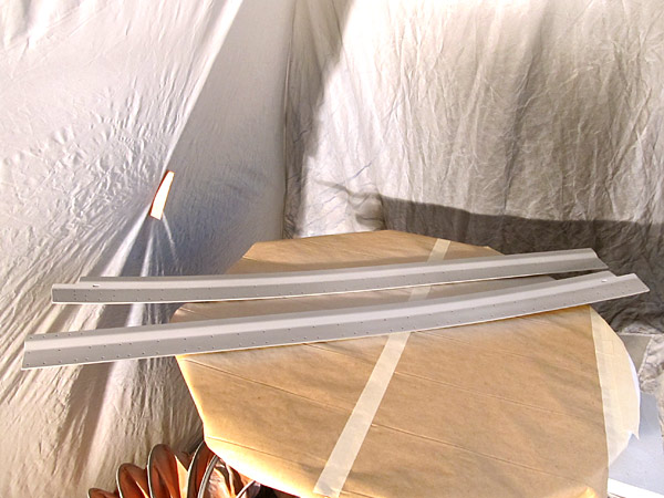
 I am priming the (F-00017-L and F-00017-R) left and right steps with SPI (Southern Polyurethanes, Inc.) 6610-4 gray epoxy primer. |
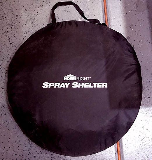 This spray booth folds up into a small carrying bag when not in use. |
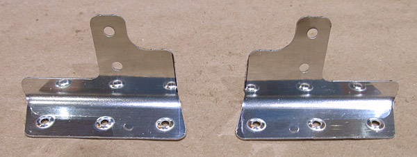
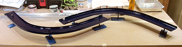
 I painted the (F-00017-L and F-00017-R) left and right steps with UTECH 500 gloss black paint. |
 I painted the (F-00017-L and F-00017-R) left and right steps with Alclad ALC 107 chrome. |
 In order to protect the finish I painted the (F-00017-L and F-00017-R) left and right steps with three coats of Alclad ALC 310 clear lacquer at 22 psi. |
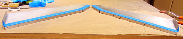
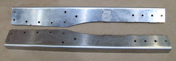
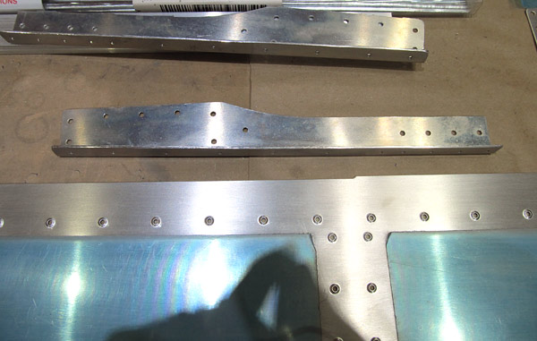
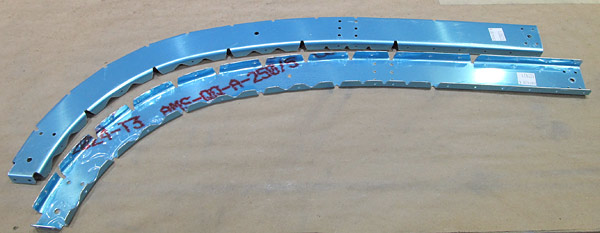
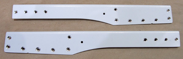
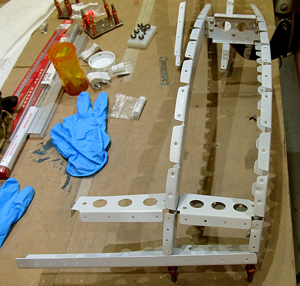
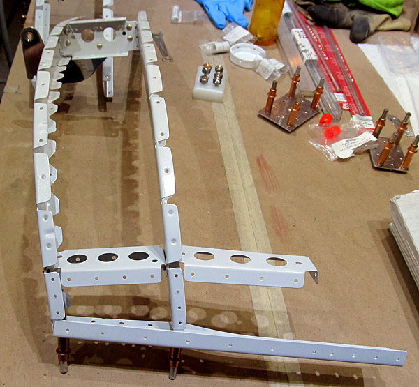
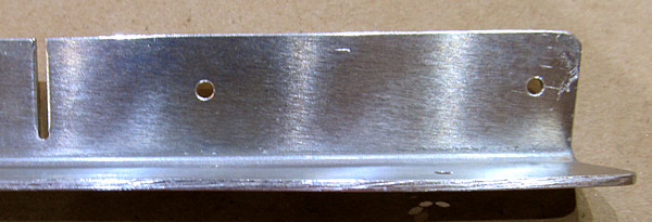
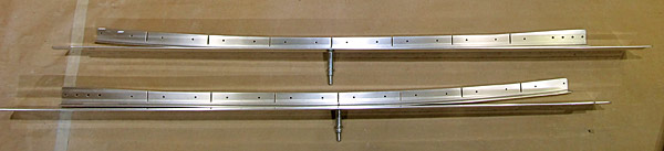
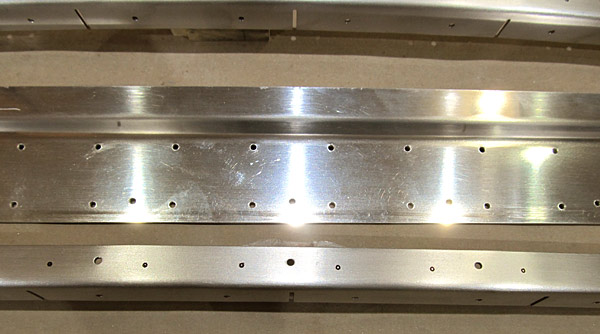
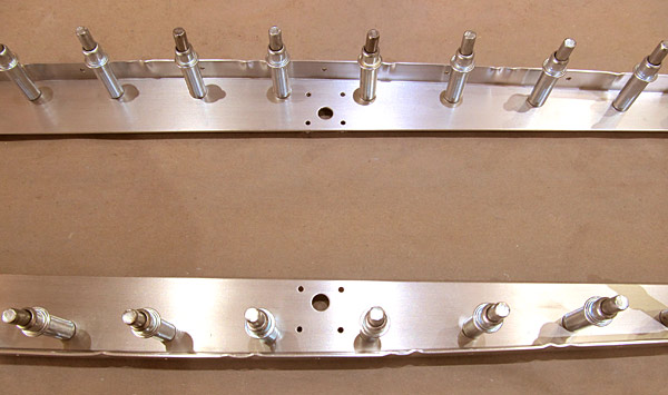
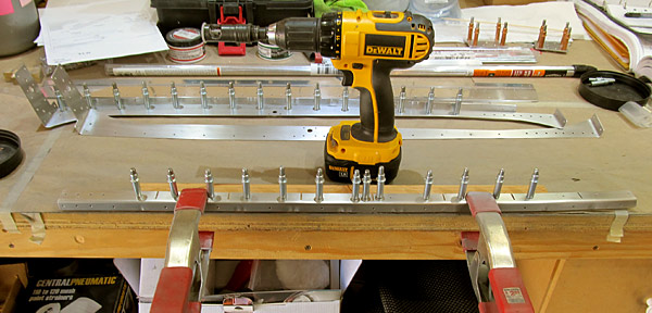
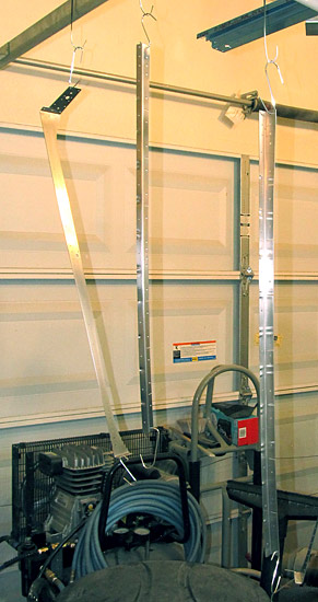
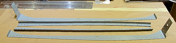
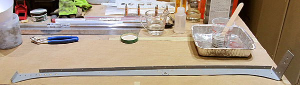
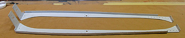
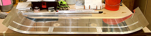
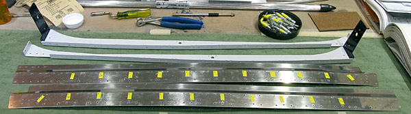
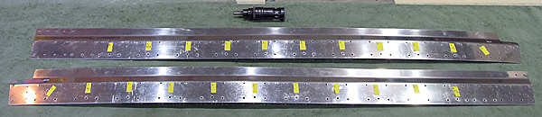
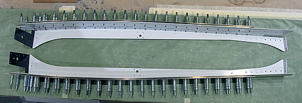
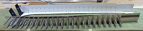
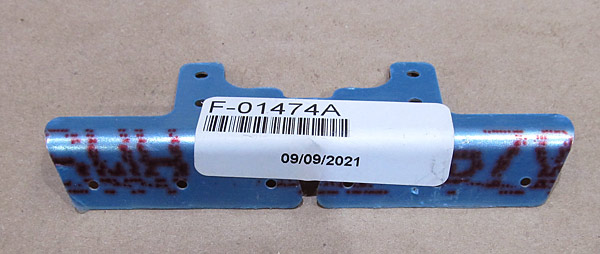 As per step one, on page 38-04, referencing figure one, the (F-01474A-L and F-01474A-R) left and right stiffener angles need to be dimpled to accept (AN426AD3-4) rivets. |
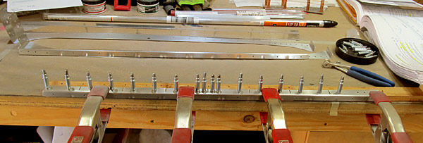
 I am using 3/32" dimple dies and our DRDT2 dimple machine to dimple the stiffeners. |
 *Make sure to reference figure one on page 38-04 so that the correct side of the (F-01474A-L and F-01474A-R) stiffener angles are dimpled. |
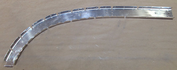
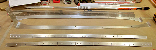
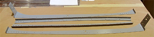
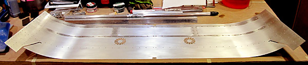
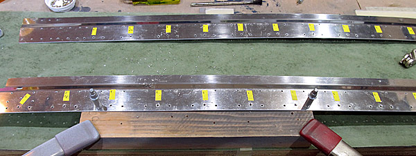
 I drew layout lines onto the (F-01474A-L and F-01474A-R) stiffener angles because in step two, on page 38-04, figure one, they need to be separated into two parts. |
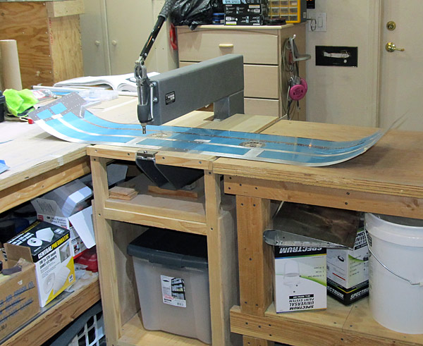
 I used a bandsaw to separate the (F-01474A-L and F-01474A-R) stiffener angles. |
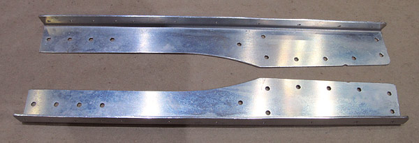
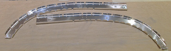
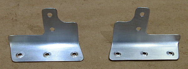 All of the holes and edges of the (F-01474A-L and F-01474A-R) left and right stiffener angles were deburred and the surfaces were scuffed with a maroon Scotch-Brite™ pad in preparation for painting. |
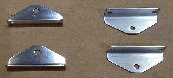
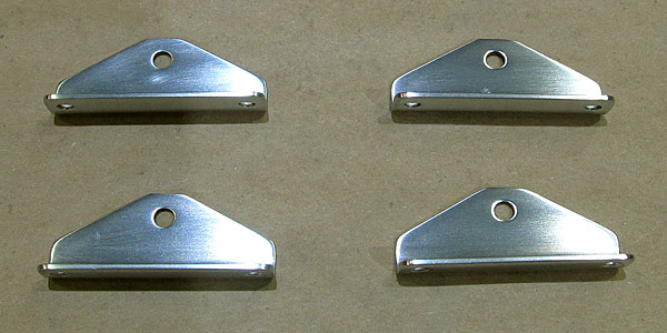
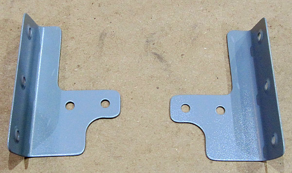
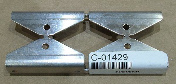 The (C-01429) latch bellcrank angles need to be separated next... |
 As per step ten, on page 38-04, figure three, I separated the (C-01429) latch bellcrank angles into four parts using our bandsaw. |
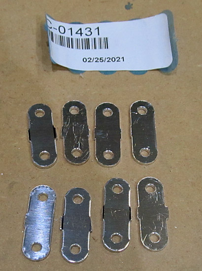
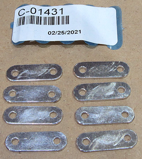
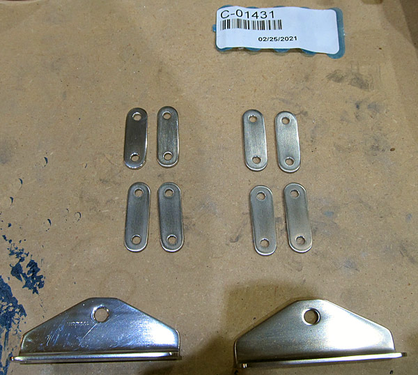
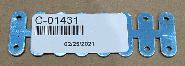 The (C-01431) latch links need to be separated. |
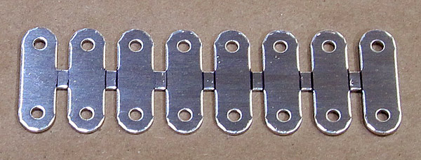 I drew layout lines onto the (C-01431) latch links to guide the cutting process on the bandsaw. |
 As per step eleven, on page 38-04, figure four, I separated the (C-01431) latch links into eight parts using our bandsaw. |
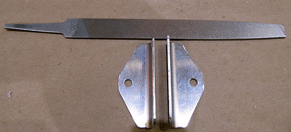 I am deburring the edges and holes of the (C-01429) latch bellcrank angles. I always start out with a small file and then finish off with sandpaper. |
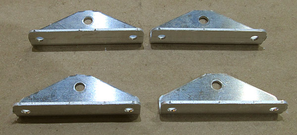
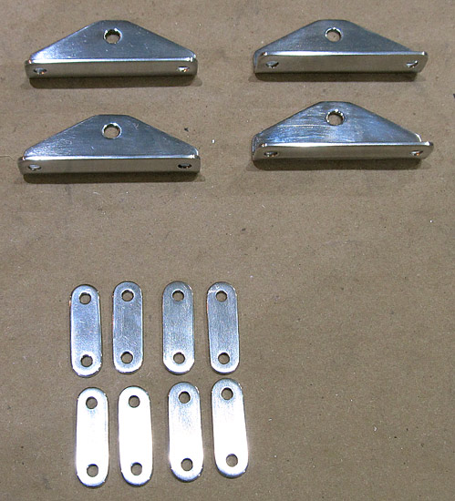
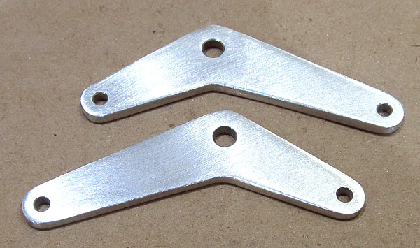
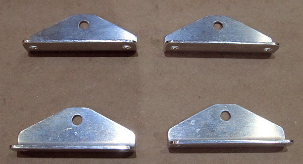 The edges of the four (C-01429) latch bellcrank angles that were separated in step ten, on page 38-04, figure three, and the holes, were deburred. |
 I am going to polish these four (C-01429) latch bellcrank angles because they will be visible in the cockpit area so it is going to start with sanding them smooth with fine grit sandpaper. |
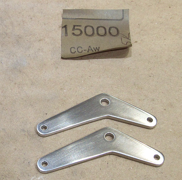
 The sanding process starts out with 320 grit sandpaper and continues up to 15000 grit sandpaper. |
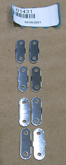
 The eight (C-01431) latch links are small so getting them ready to polish will be a challenge. I first start out with the small file to debur the edges and debur the holes. |
 The edges of the eight (C-01431) latch links have been deburred and sanded, and now comes the tedious task of polishing them. |
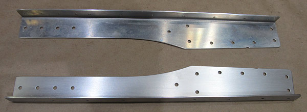
 I primed the (F-01474A-L and F-01474A-R) left and right stiffener angles with SPI 6610-4 gray epoxy primer. |
 The eight (C-01431) latch links that were separated in step eleven, on page 38-04, figure four, are in the sanding phase of being polished. |
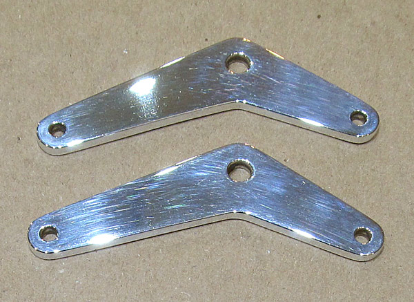
 The top four (C-01429) latch bellcrank angles have had some polishing done on the buffing wheel. |
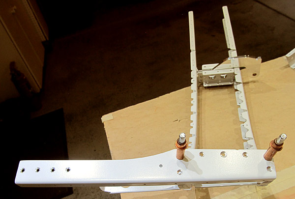
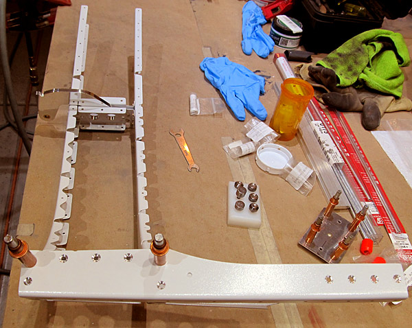
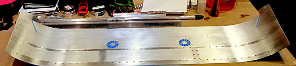
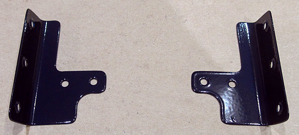 I painted the two (F-01474A-L and F-01474A-R) stiffener angles with Stewart Systems Ekocrylic E5465 Royal Blue, which is the same color that the roll bar assembly is painted. |
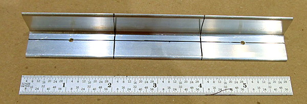
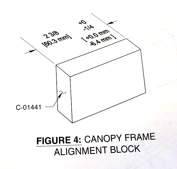 Since I had the miter saw out working on another project I thought I would jump ahead to step six, on page 38-19, figure four and fabricate the four (C-01441) canopy frame alignment blocks. |
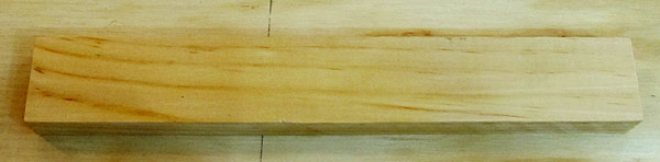 The (C-01441) canopy alignment blocks are cut out from one piece of wood supplied in the kit. This is what it looks like before cutting the blocks. |
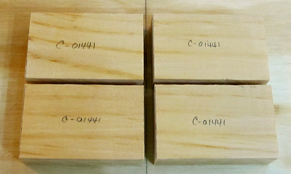 Four (C-01441) canopy frame alignment blocks! |
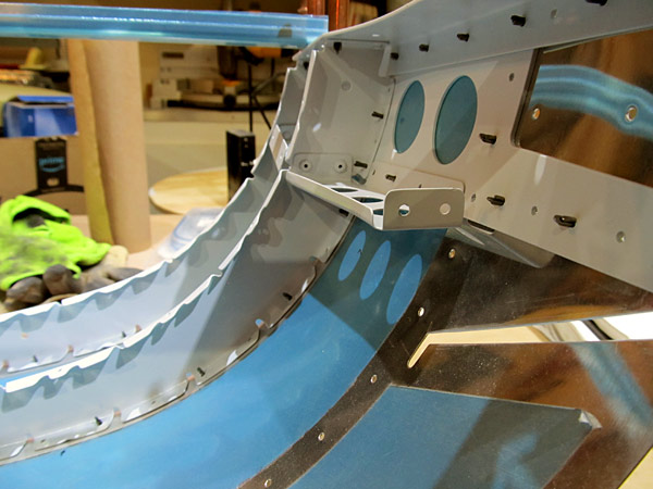
 The (F-01474A-L and F-01474A-R) left and right stiffener angles are positioned at the base of the roll bar assembly so part of the stiffener angle is painted royal blue, to match the roll bar color, and the other half of the stiffener angle is riveted onto the aft fuselage top side skins, which is smoke gray. |
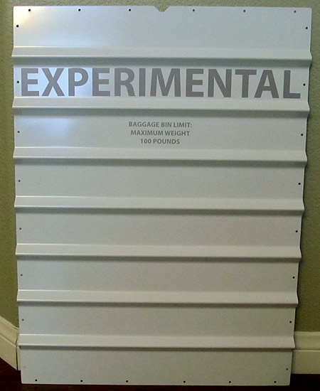 I applied the required "Experimental" placard to the (F-01406F) baggage bulkhead corrugation. |
 The second half of the two (F-01474A-L and F-01474A-R) left and right stiffener angles were painted with Stewart Systems E5301 Ekocrylic smoke gray paint. |
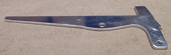
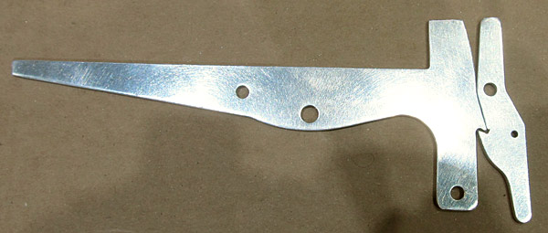
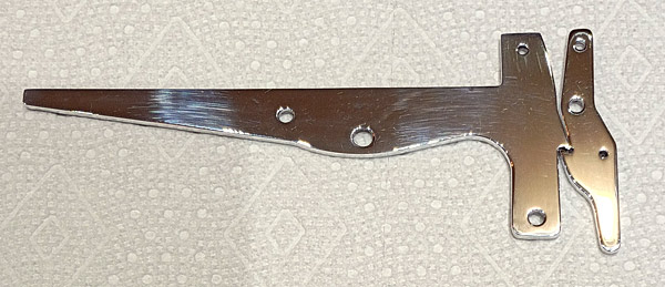
 As per step one, on page 38-05, I checked the flatness of the (C-607) latch handle. |
 As per step one, on page 38-05, I checked the flatness of the (C-609) canopy latch. |
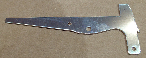 As per step two, on page 38-05, figure one, I am deburring the edges of the (C-607) latch handle. |
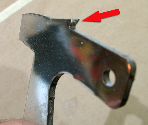 This (C-607) latch handle had a small chip in the catch; I was able to file it flat and was a little worried if the mechanism would function correctly but thankfully everything functions well! |
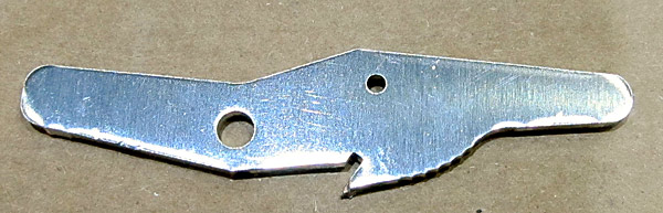 The (C-609) canopy latch is next for deburring. The edges on this is just as rough as the latch handle is.... |
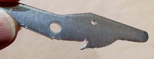 *Don't forget to inspect the notch on the (C-609) canopy latch, mine had a small chip in the notch also. |
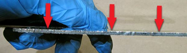
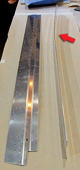
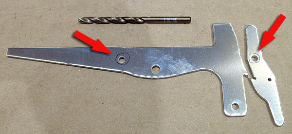 As per step three, on page 38-05, figure one, there are two holes on the (C-607 and C-609) latch handle and canopy latch that need to be final drilled #12 size. The photograph shows these holes circled with a sharpie pen. |
 Back to deburring the edges on the (C-607) latch handle.... |
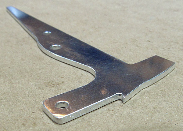 I deburred the edges of the (C-607) latch handle and am now starting to sand them smooth. |
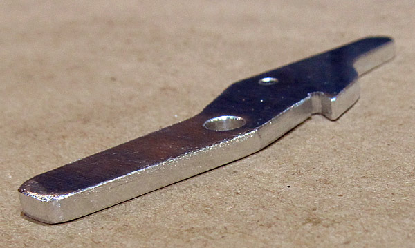 The edges and the holes have been deburred on the (C-609) canopy latch. |
 Remember the chips in the notches of the (C-607 and C-609) latch handle and canopy latch? |
 The edges on the (C-607) latch handle and the (C-609) canopy latch have been final sanded and polished. |
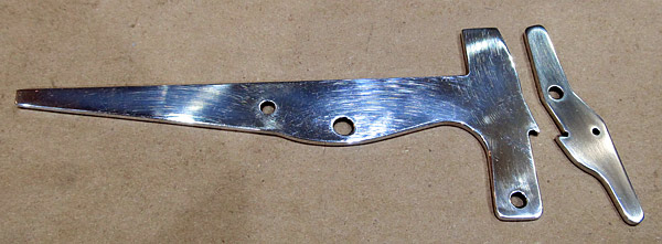 The surfaces on the (C-607) latch handle and the (C-609) canopy latch have been final sanded and ready to be polished. |
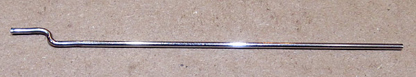 I polished the (SL-3) with Nuvite NuShine IIS, it is a final grade metal polishing compound. |
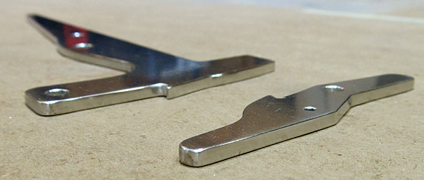
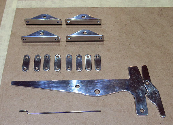 These are the canopy and door latching parts, they have been polished with Nuvite NuShine IIA polishing compound "grade A" which is a fine metal polishing compound used just before the final mirror finish compound Nuvite NuShine IIS. |
 The (C-607) latch handle and the (C-609) canopy latch have been polished with Nuvite NuShine IIS final metal polishing compound. |
 The (F00017-L and F-00017-R) left and right steps are masked off so that they can be painted with wing walk material. |
 I painted the treads on the (F00017-L and F-00017-R) left and right steps with Randolph's wingwalk paint. |
 This is what two coats of the Randolph's wingwalk mixture looks like when fully dried. |
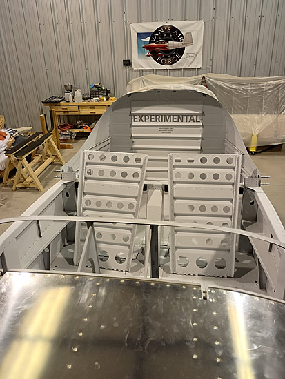 I temporarily installed the (F-01406F) baggage bulkhead corrugation after applying the "Experimental" placard to the aft portion of the baggage bin. |
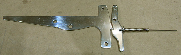
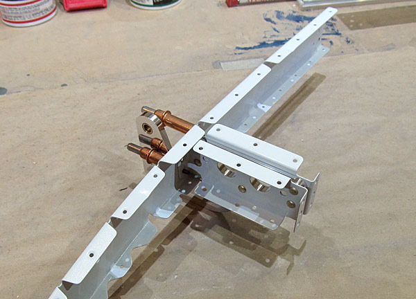
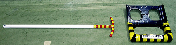
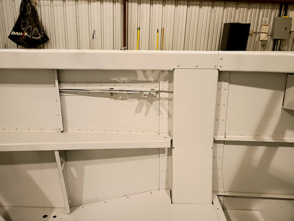 As per step eight, on page 38-05, figure one, I installed the door latch mechanism to the fuselage to check for fit and function. |
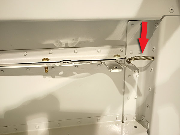 This is what I mean when I mention the flex of the (C-615) spring. There is supposed to be a modification that can take care of this and make everything work in a more "solid" action. |
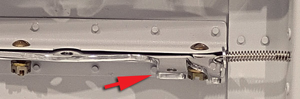
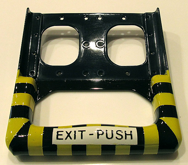
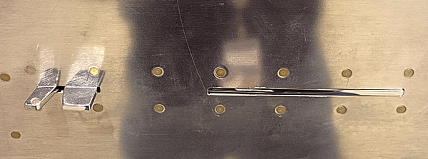 This is what the door latch mechanism looks like from the exterior of the fuselage. |
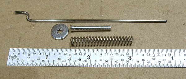
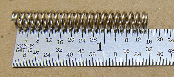 This is the (C-615) door latch spring. |
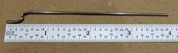 The (SL-3) rod is part of the latching mechanism, it connects to the (C-609) canopy latch through the (C-615) spring to a hole in the (F-01487-L) center section channel. The rod is more or less a guide to keep the mechanism in alignment. |
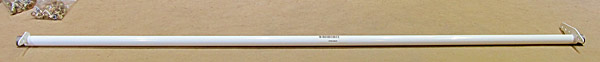
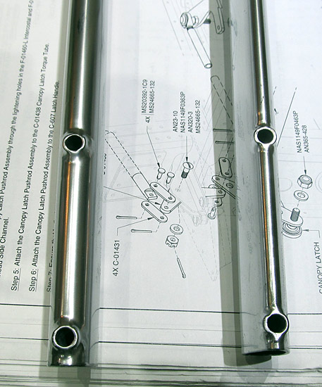
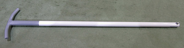
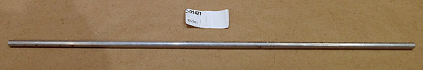 This is the (C-01421) canopy latch pushrod. It connects the door latch assembly to the canopy latch torque tube assembly which engages the canopy latch pins to lock the canopy when flying. |
 I polished the (C-01421) canopy latch pushrod with Nuvite NuShine IIS metal polishing compound. |
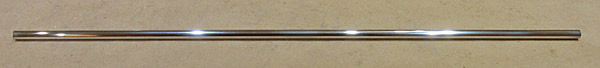
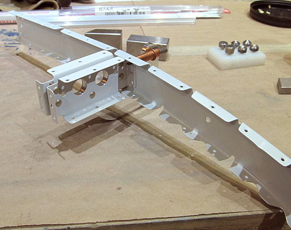
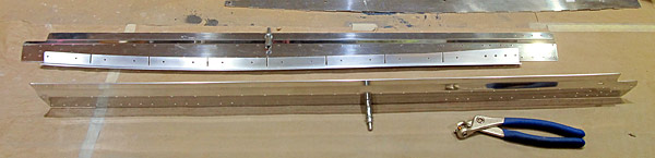
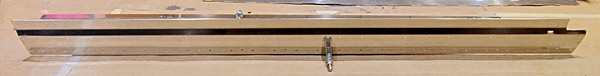
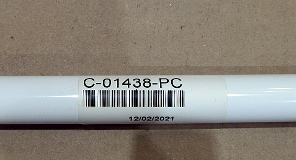 This is the (C-01438) canopy latch torque tube. |
 The (C-01438) canopy latch torque tube is 42 7/8" long. |
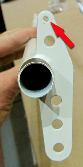 As per step ten, on page 38-05, figure three, the 1/8" hole on the (C-01438) canopy latch torque tube needs to be final #30 drilled. |
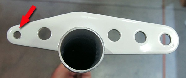 The 1/8" holes were final #30 drilled and deburred on each side of the (C-01438) canopy latch torque tube. |
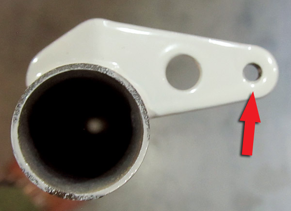 Additionally according to figure three, on page 38-05, there is a 1/4" hole that needs to be final drilled, it is only on the left side. |
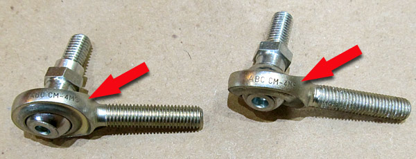 As per step thirteen, on page 38-05, figure four, there needs to be two (CM-4MS) bearings attached to the ()1421) canopy latch pushrod. |
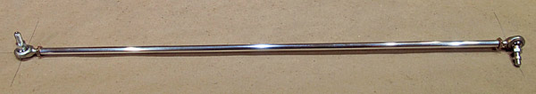 As per step thirteen, on page 38-05, figure four, the Canopy Latch Pushrod Assembly was fabricated by attaching the two (CM-4MS) angular bearings to the (C-01421) canopy latch pushrod and clocking them 90° from each other at a length of 20 13/16". |
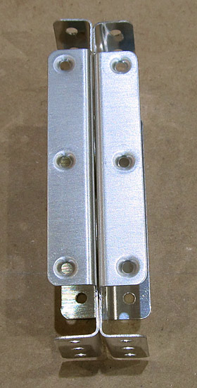
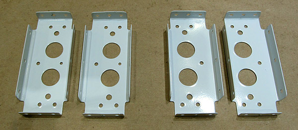
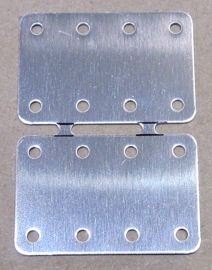
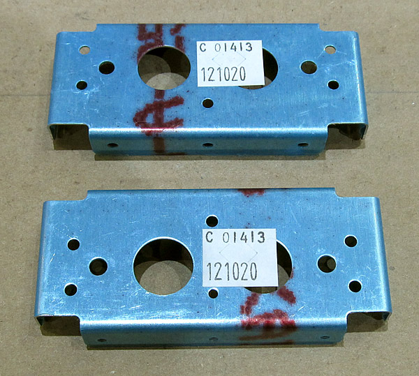 The edges and the holes need to be deburred on the (C-01413) inboard hinge intercostals. There are two of these. |
 The edges and the holes of the (C-01413) inboard hinge intercostals were deburred. |
 The surfaces of the (C-01413) inboard hinge intercostals were scuffed with maroon Scotch-Brite™ pads in preparation for priming. |
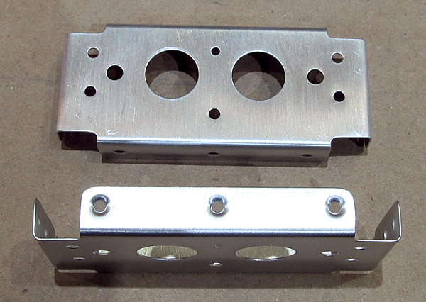 As per step eight, on page 38-06, figure two, the top flanges of the two (C-01413) inboard hinge intercostals, were dimpled with 3/32" reduced diameter female dimple die sets using our hand squeezer. |
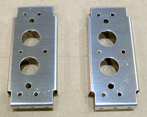
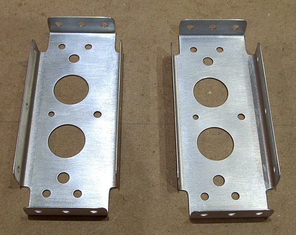
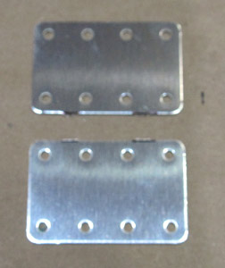
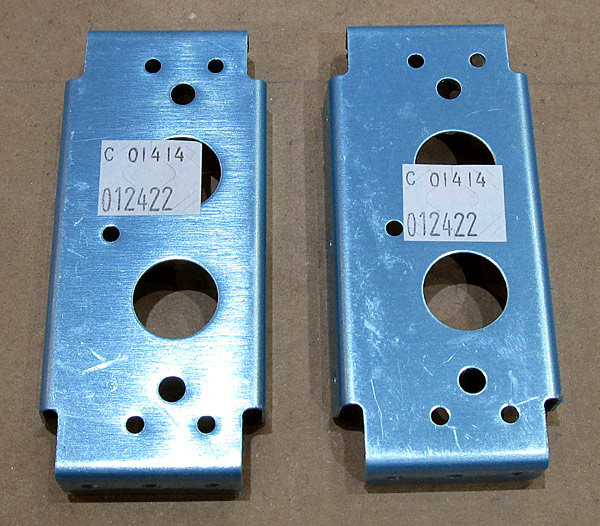 The two (C-01414) outboard hinge intercostals need to be deburred. |
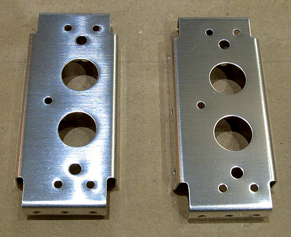 The edges and the holes were deburred. |
 As per step eight, on page 38-06, figure two, the top flanges of the (C-01414) outboard hinge intercostals were dimpled with 3/32" reduced diameter female dimple die sets using a hand squeezer. |
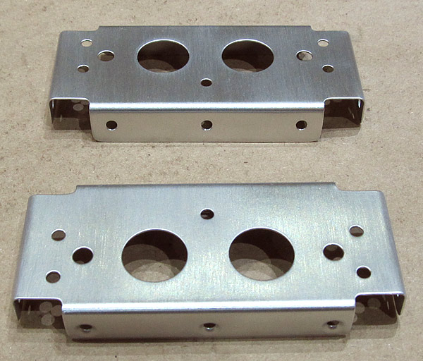 The surfaces of the (C-01414) outboard hinge intercostals were scuffed with maroon Scotch-Brite™ pads in preparation for priming. |
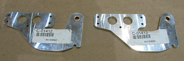 These are the two (C-01412) canopy hinges. They need to be deburred and I have elected to polish them to a mirror finish. |
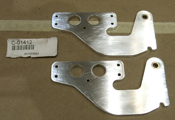 As I began to sand the surfaces for polishing I noticed that there was a shallow groove on each of the hinges (you can see them on the left part of the tab in this photograph). |
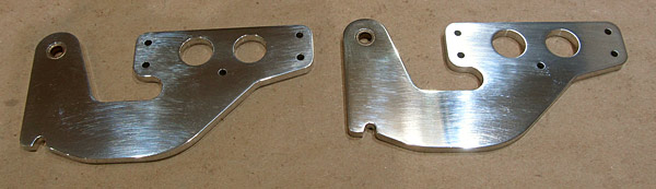 I start with 320 grit sandpaper and end with 15000 grit and then final polish with Nuvite NuShine IIS metal polish. This is about the 5000 grit portion of the sanding. |
 I primed the (C-01413 and C-01414) inoboard and outboard hinge intercostals with SPI 6610-4 gray epoxy primer. |
 The (C-01412) canopy hinges are still being sanded to 15000 grit sandpaper and will soon be ready to be polished with Nuvite NuShine IIA and IIS polishing compound. |
|
As I explained earlier I didn't like the way that the (C-615) spring "kinked" when it was in position in the canopy latch assembly. |
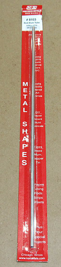 First I need to get some aluminum tubing, at first I thought that 5/32" diameter tubing would work but it was too wide so I ended up using 1/8" tubing which fit better inside the (C-615) spring. |
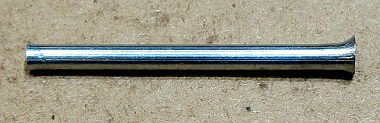 Next, one end of the tubing needs to be flared, I used a dowel rod to make the flare. The aluminum is soft enough to make the flare but it does take some effort to get the job done....not too hard, not to soft. |
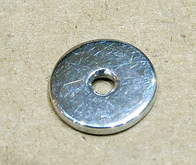 This is a stop washer that will prevent the flared aluminum tube to ride up over the (C-609) canopy latch. |
 These are all of the parts for the modification, everthing was polished with Nuvite NuShine IIS metal polish. |
 This is how everything goes together, I need to install it onto the airframe and check the function... |
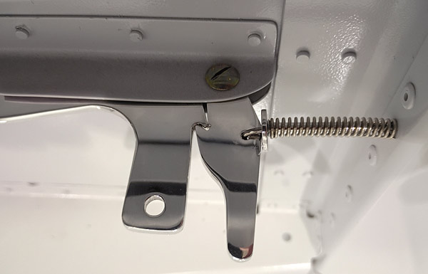 I reattached the canopy latch assembly with the new parts described above and the fit is much better. |
 This is another view of the canopy latch assembly with the new parts added. I haven't installed the (VA-104-1A) knob to the (C-607) latch handle yet. |
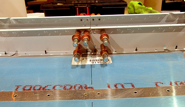
 As per step nine, on page 38-06, figures three and four, the (C-01413) inboard hinge intercostals and the (C-01414) outboard hinge intercostals were clecoed to the (C-01412) canopy hinges so that they could be riveted together with AN470AD4-8 rivets. |
 The smaller #40 hole defines the inside half of the canopy hinge assembly so double check how everything is clecoed together before riveting. |
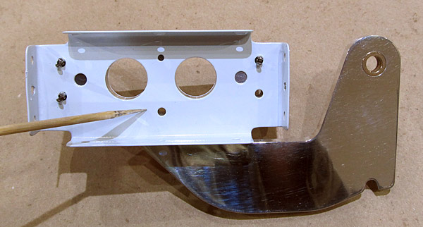
 Before I rivet the canopy hinge assemblies together I wanted to final size the holes in the (F-00017-L and F-00017-R) steps. |
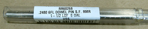
 The holes in the (F-00017-L and F-00017-R) steps were final sized using a .2480" ream on the drill press. |
 Back to the riveting... |
 This is the piece that the (C-01406) forward canopy rails are separated from. |
 I used a sharpie pen to lay out the cut lines and separated them using a bandsaw. |
 As per step one, on page 38-07, figure one the two pieces were separated. Now there is (C-01406-L) left foward canopy rail and a (C-01406-R) right forward canopy rail. |
 As you can see, the bandsaw cut needs to be filed and deburred and the material is thick. |
 The edges and all of the holes were deburred on the (C-01406-L) left forward canopy rail. I also used 220 grit sandpaper to smooth out the edges. |
 The (C-01406-R) right forward canopy rail is next to be deburred. As you can see, the edges are rough and when I cut them on the bandsaw I cut just a little wide of the line so there is plenty of file work to do at first. |
 The edges and all of the holes on the (C-01406-R) right forward canopy rail have been deburred and smoothed with 220 grit sandpaper. |
 I will probably sand the edges on the (C-01406-L and C-01406-R) left and right forward canopy rails up to 400 grit sandpaper. |
 The edges of the (C-01406-L and C-01406-R) left and right forward canopy rails were sanded and polished starting with 320 grit sandpaper and ending with 600 grit sandpaper. |
 I scuffed the surfaces of the (C-01406-L and C-01406-R) left and right forward canopy rails with maroon and gray Scotch-Brite™ pads in preparation for priming. |
 All of the holes in the (C-01430) latch bellcranks were deburred as well as the edges of the left latch bellcrank....the right bellcrank still has to have edges deburred. |
 I deburred the edges of the second (C-01430) latch bellcrank. |
 The goal is to sand the surfaces up to 15000 grit sandpaper and then begin the polish process, I am using Nuvite NuShine polishes for the final polishing of the surfaces. |
 I start out with Nuvite NuShine IIA (red label) and finish with Nuvite NuShine IIS (green label) polish. |
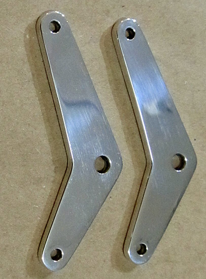 This is after the Nuvite NuShine IIS has been applied by hand, for better results a rotary buffer can be used but these parts are so small I prefer to just hand polish them. |
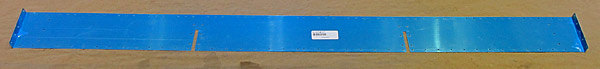
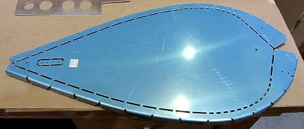 The (C-01404-L and C-01404-R) left and right support flanges and the (C-01404A) support flange splice need to be separated from this single piece of aluminum. The protective blue vinyl will be removed first. |
 The protective blue vinyl was removed from the edges and all of the holes were deburred first. |
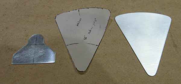 Since I was going to be using the bandsaw I thought it would be a good idea to cut out some of the contour templates that will be used later in the fiberglass portion of the canopy build, (see pages 38-25 and 38-41). |
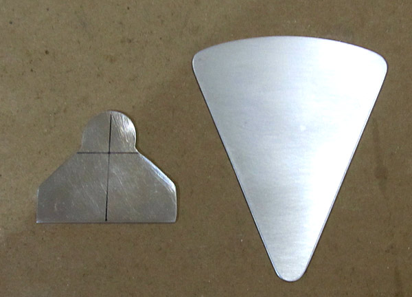 These are the two types of templates that will be used later in the fiberglass lay up of the canopy, they have been cut out using the bandsaw and then deburred and smoothed out with sandpaper. |
 Now it's time to separate the (C-01404-L and C-01404-R) support flanges and the (C-01404A) support flange splice. I did that using our bandsaw. |
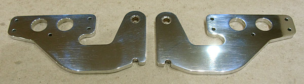
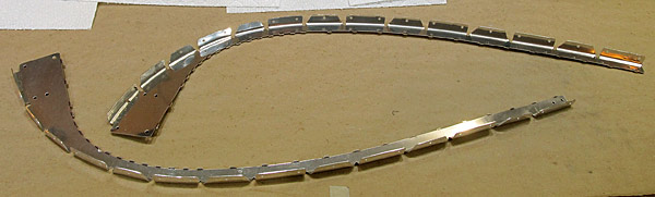 These are the (C-01404-L and C-01404-R) left and right support flanges. |
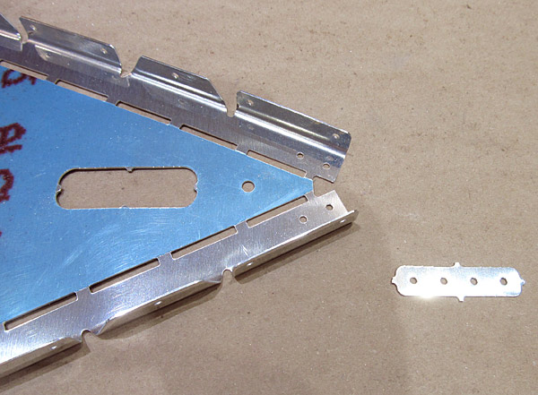 This is the (C-01404A) support flange splice. I separated it using a small metal cutting hand saw. |
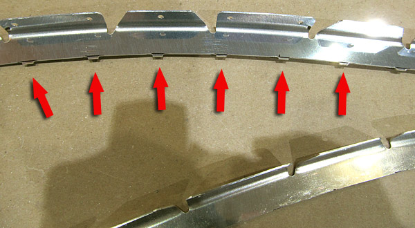 Now to debur the edges of the (C-01404-L and C-01404-R) left and right support flanges. As you can see the "nubs" that held these flanges onto the teardrop piece of aluminum are going to consume some deburring time with a small file. |
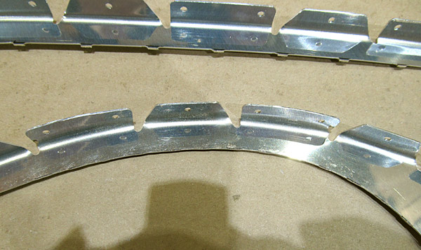 The (C-01404-L) left support flange has been deburred using a small file and the (C-01404-R) right support flange (above) has yet to be deburred. |
 Here is a better picture of the (C-01404-L) left support flange deburred. |
 Of course some of the hardest spots to be deburred are the little gaps between the individual flanges, I still use a small round file to get to those... |
 The (C-01404-L and C-01404-R) left and right support flanges and the (C-01404A) support flange splice have been deburred and the edges have been polished smooth with sandpaper. |
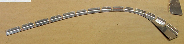
 I like to scuff the surfaces of the pieces that I know are going to be painted so now I am scuffing the (C-01404-L and C-01404-R) left and right support flanges with maroon and gray Scotch-Brite™ pads. This is the finished right support flange. |
 This is the (C-01404-L) left support flange, it has been finish scuffed with maroon and gray Scotch-Brite™ pads in preparation for painting. |
 The (C-01404-L and C-01404-R) left and right support flanges, and the (C-01404A) support flange splice have been scuffed and will be primed and painted after final fitting has been completed. |
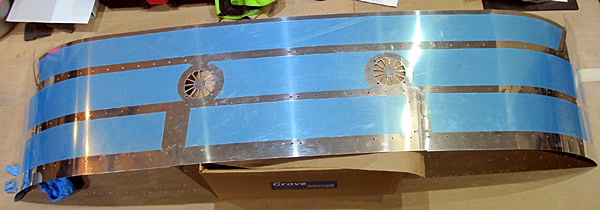
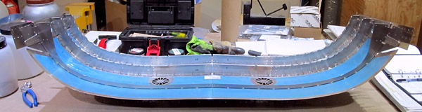
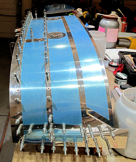
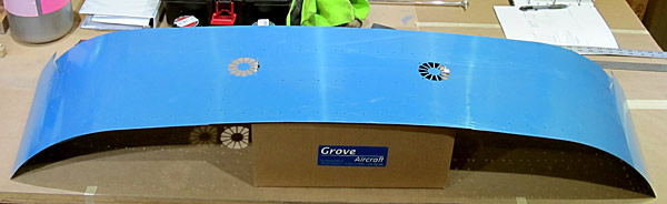 This is the (C-01418) tip up canopy skin. For now I only want to remove the protective blue vinyl in the places that will be riveted so that the majority of the skin can be protected from scratches as much as possible. |
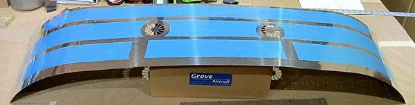 I used a small tipped soldering iron to remove the blue vinyl from the seams that will eventually be dimpled and riveted. |
 This is the bottom surface of the (C01418) canopy skin. |
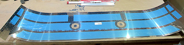
 I deburred all of the holes in the (C-01418) canopy skin and have deburred the edges, the slots in the cooling fan openings still have to be deburred. |
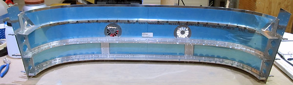
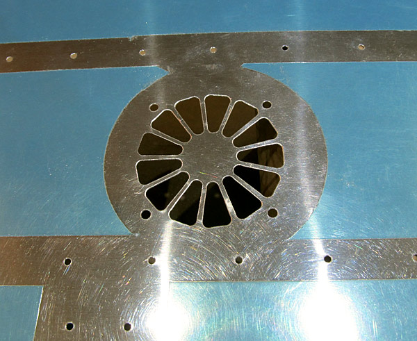 The fan slots in the (C-01418) canopy skin (right side) were deburred. These are deburred using a small round file....tight maneuvering! |
 Both sets of fan slots in the (C-01418) canopy skin were deburred, final sanding to go... |
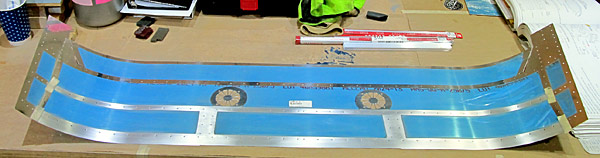 The edges of the (C-01418) canopy skin were sanded and polished smooth with sandpaper (up to 600 grit). The bare places on the skin that are going to be dimpled next were scuffed with maroon and gray Scotch-Brite™ pads; it's just easier to scuff the surfaces now then after they have been dimpled. |
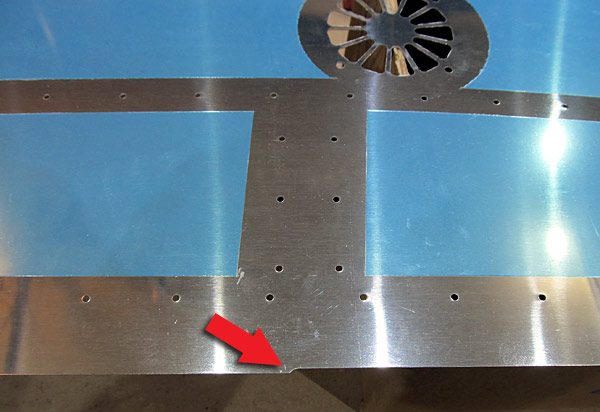
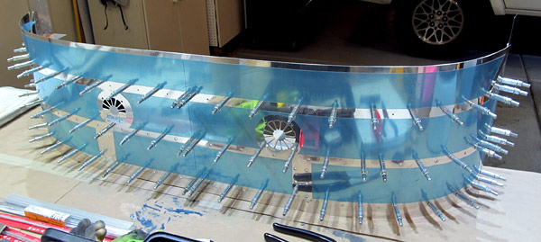
 As per step three, on page 38-07, figure three, there are indicated holes that need to be dimpled on the (C-01418) canopy skin at this time. |
 Make sure to start in the middle and work symmetrically outboard when dimpling and use plenty of support under the (C-01418) canopy skin. |
 These are the dimpled holes... |
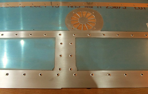
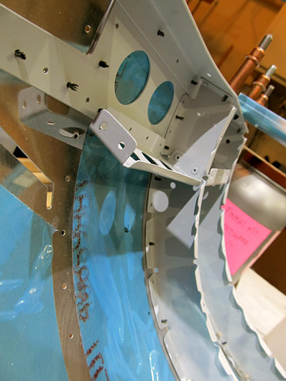
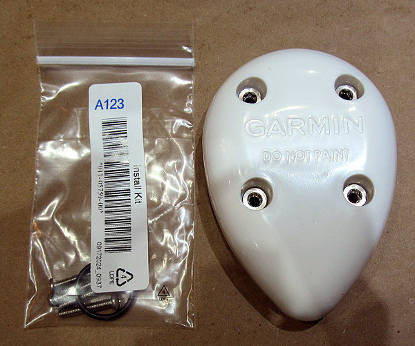 On a side note, I received a Garmin GA-35S WAAS GPS antenna and I need to fabricate a doubler for it so it can be mounted on the dorsal side of the fuselage just aft of the rear window. |
 This is the dorsal section of the fuselage where I intend to mpunt the GPS antennas. |
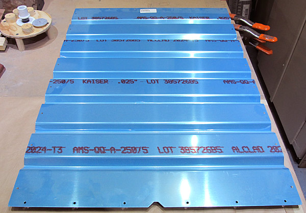
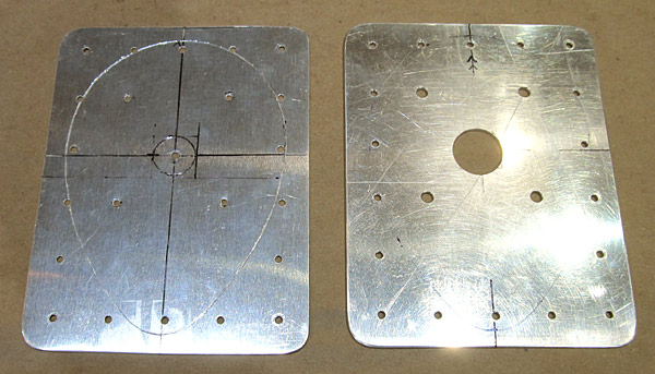
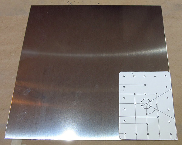 Garmin recommends using .063" 2024 T3 Alclad aluminum for the doubler so that is what the doubler will be fabricated from. |
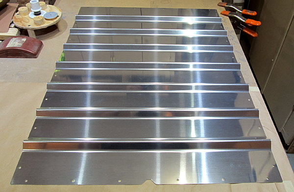
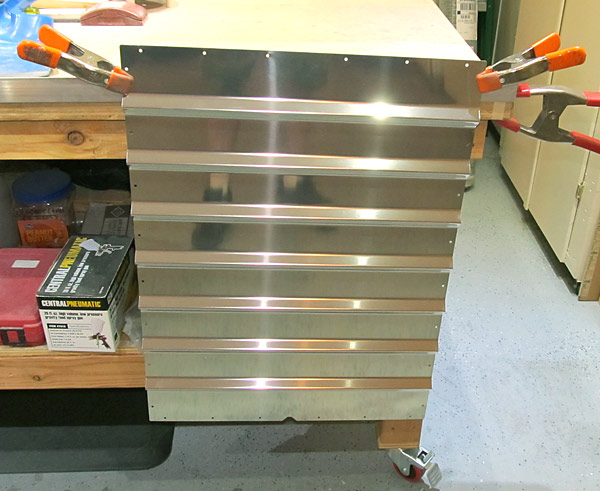
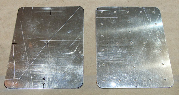 Using the template found online for the Garmin GA-35 WAAS GPS antenna doubler, I cut out two doublers from the .063" 2024 T3 Alclad aluminum using our bandsaw. |
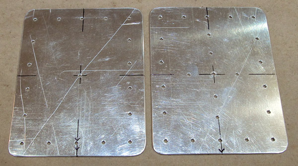 A Garmin GA-35S WAAS GPS antenna will not work with a doubler drilled out like this if you enlarge the center hole in the center position indicated, the result would be that the antenna sticks out a 1/4" past the edge of the doubler....ask me how I know! |
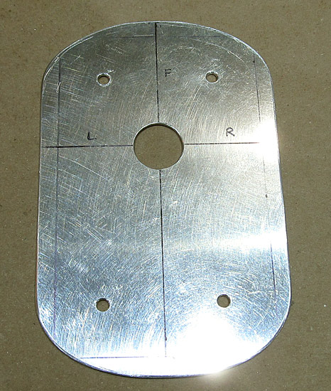
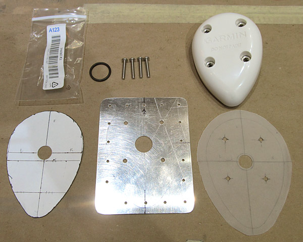 These are all of the parts and templates that I used to fabricate the doubler for the Garmin GA-35S WAAS gps antenna. |
 The template on the left of this photogragh is just a thin aluminum drilling guide that I will use to match drill the aircraft skin with. The holes are all #40 drill holes and after they are all drilled into the skin, I will final size them to fit the doubler. |
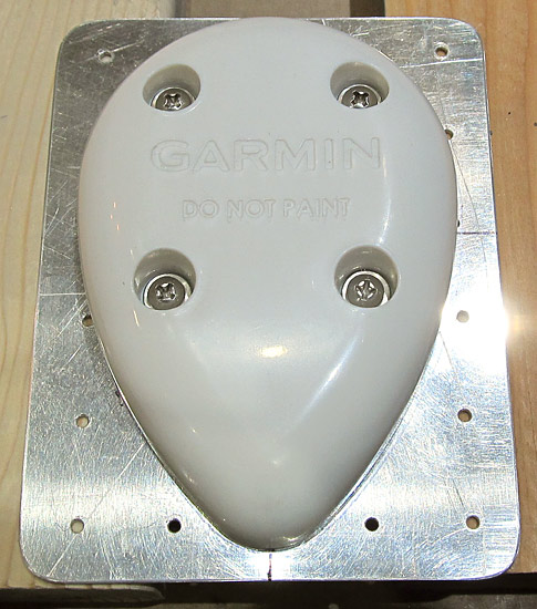 This is the final doubler with the Garmin GA-35S WAAS GPS antenna attached to it. The antenna will be attached to a Garmin navigator. |
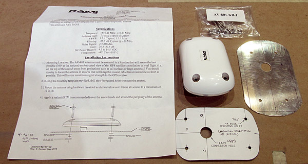 I am installing a second RAMI AV-801 WAAS GPS antenna to our airplane, it is going to be used by a panel mounted iPad system for pitot/static and independant AHRS PFD for the right side of our instrument panel. |
 I fabricated the doubler from .063" 2024 T3 alclad aluminum as well. The center hole is 11/16" in diameter but it can be as small as 5/8". The four mounting screws are #6-32 size. |
 These are the two GPS antenna doublers. |
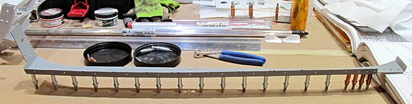
 There are six separate canopy frames that make up the core of the tip-up canopy section and each of them need to be deburred. The frames are left and right specific and are attached in the middle by splice plates; when assembled they span just a little over 46". |
 I am using a small file to debur the edges of the (C-01403-L) mid canopy frame and all of the holes have been deburred as well. |
 This is the (C-01403-R) right mid canopy frame. The protective blue vinyl has to be removed and the deburring process begins again. |
 I like to use small files to debur the edges of the material, but first I wash off the red ink with acetone. |
 This is what the edges look like after they have been deburred with the file. Later I will polish them with fine sandpaper. All of the holes have been deburred too. |
 As per step five, on page 38-08, figure two, the (C-01408) forward canopy rail bases need to be separated. |
 I used a fine line sharpy pen to lay out the cut lines before going over to the bandsaw to separate the pieces. |
 The (C-01408) forward canopy rail bases have been separted using the bandsaw and some heavy duty deburring needs to be done now! |
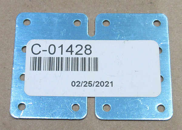 Since I have the bandsaw out, I might as well separate the (C-01428) canopy frame splices. |
 I removed the protective blue vinyl and laid out the cut lines with a fine line sharpy pen. |
 As per step six, on page 38-08, figure three, I separated the (C-01428) canopy frame splices on the bandsaw. |
 The edges of the (C-01428) canopy frame spices were deburred with a small file and then the edges were polished with fine sandpaper. All of the holes were deburred. |
 The edges of this (C-01408) forward canopy rail base was deburred with a small file and all of the holes were deburred. |
 I finished deburring the edges of the second (C-01408) forward canopy rail base and polished the edges of the two forward canopy rail bases with fine sandpaper. |
 I began scuffing the surfaces of the (C-01408) forward canopy rail bases with maroon and gray Scotch-Brite™ pads in preparation for priming. |
 Both of the (C-01408) forward canopy rail bases have been scuffed with maroon and gray Scotch-Brite™ pads. |
 Ready for paint! |
 I have begun polishing the edges of the (C-01403-L and C-01403-R) left and right mid canopy frames with fine sandpaper. |
 I scuffed the surfaces of the (C-01403-L and C-01403-R) left and right mid canopy frames with maroon and gray Scotch-Brite™ pads in preparation for priming. |
 These are the (C-01403-L and C-01403-R) left and right mid canopy frames laid out as they will be used in the tip up canopy. |
 There are three rows of canopy frames in the forward part of the tip up canopy. These are the (C-01402-L and C-01402-R) left and right forward canopy frames; they will be joined in the center with a (C-01428) canopy frame splice. |
 After the protective blue vinyl has been removed the edges of the canopy frames will be deburred first. |
 I started with the (C-01402-L) left forward canopy frame first and deburred the edges with a small file. All of the holes have been deburred as well. |
 This is what the edges look like after they have been deburred with the small files....polishing the edges with fine sandpaper comes next. |
 I deburred the edges of the (C-01402-R) right forward canopy frame, deburred all of the holes, and polished the edges with fine sandpaper. |
 I scuffed the surfaces of the (C-01402-L) left forward canopy frame with maroon and gray Scotch-Brite™ pads in preparation for priming. |
 I scuffed the surfaces of the (C-01402-R) right forward canopy frame with maroon and gray Scotch-Brite™ pads in preparation for priming. |
 There are three rows of canopy frames in the forward part of the tip up canopy. |
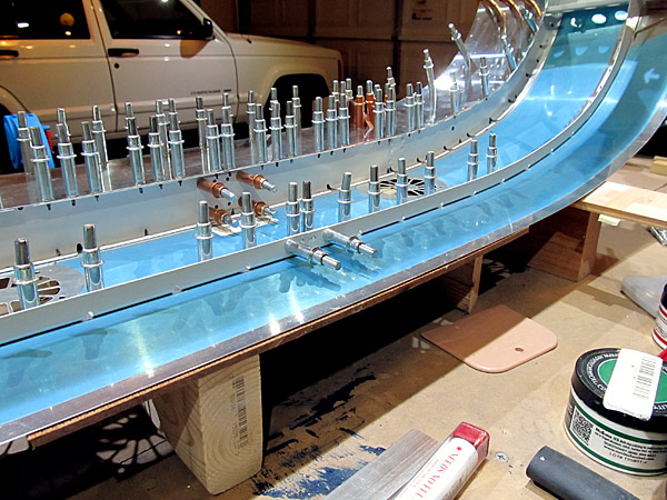
 As per steps one and two, on page 38-08, and referencing figure one, the (C-01402-L and C-01402-R) left and right forward canopy frames and the (C-01403-L and C-01403-R) left and right mid canopy frames need to be fluted so that the holes in the pre-dimpled frames match up to the holes in the (C-01418) canopy skin and also conform to the curvature of the skin. |
 This photogragh shows what the flutes look like. |
 If you look close at this photogragh you can see that the flange hole still isn't quite lined up with the canopy skin hole underneath. |
 Here is an even closer look at what I was talking about; the holes aren't lined up, you can see a small "sliver" of metal on the edges of the hole underneath so a flute is required. |
 Once the right forward frame was fluted it is time to flute the (C-01402-L) left forward canopy frame. Start clecoing every other hole from the center and work outwards. |
 Sometimes it helps to stand the canopy skin and frames on end so that the fluting progress can be checked not only for hole alignment but for gaps between the flanges and the canopy skin. |
 Here is a gap between the flange hole and the canopy skin. The dimpled skins are not nesting within each other just yet. A deeper flute or possibly a double flute might be required. |
 Time to start the fluting process again but this time it is the (C-01403-L and 01403-R) left and right mid canopy frames that need fluting. |
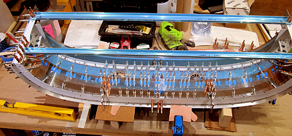
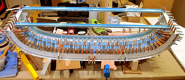
 I have all of the canopy frames clecoed to the canopy skin as well as the support flanges. The fluting is done, now it is time to check for gaps. |
 As per step three, on page 38-08, the flanges of the (C-01402-L and C-01402-R) and (C-01403-L and C-01403-R) canopy frames and the (C-01404-L and C-01404-R) support flanges were verified to lay flat against the (C-01418) canopy skin. |
 That's a lot of clecos! |
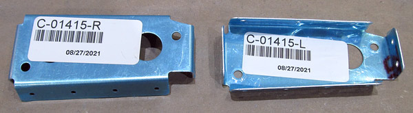 Time to remove the protective blue vinyl and debur the (C-01415-L and C-01415-R) left and right forward intercostals. |
 The edges of the (C-01415-L and C-01415-R) left and right forward intercostals were deburred with a small file and then polished with fine sandpaper. All of the holes were deburred as well. |
 Time to remove the protective blue vinyl and debur the (C-01416-L and C-01416-R) left and right aft intercostals. |
 The edges of the (C-01416-L and C-01416-R) left and right aft intercostals were deburred with a small file and then polished with fine sandpaper. All of the holes were deburred as well. |
 I cleaned all of the canopy parts with soap and water and then degreased them with Southern polyurethane Incorporated waterborne wax and grease remover in preparation for priming. |
 I primed all of the canopy parts with Southern polyurethane Incorporated 6610-4 two part, gray epoxy primer. |
 I finish coated all of the canopy parts with Stewart Systems E5301 EkoCrylic waterborne smoke gray paint. |
 These parts are finish coated with Stewart Systems E5301 EkoCrylic waterborne smoke gray paint. They will make up the tip-up canopy frame. |
 The left hinge assembly was clecoed to the (C-01402-L) left forward canopy frame to be riveted into place with AN470AD4-4 rivets. |
 The right hinge assembly was clecoed to the (C-01402-R) right forward canopy frame to be riveted into place with AN470AD4-4 rivets. |
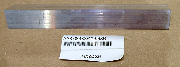
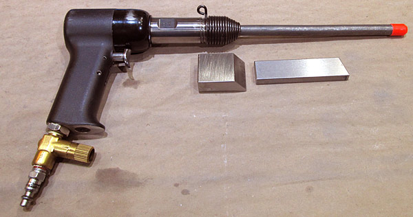 I am using our 3x rivet gun with a 1/8" cupped, 10 1/2" extension and a combination of 4" and 2" x 1 1/2" x 3/4" tungsten bucking bars to do the job. |
 It's been a while since I used the rivet gun last so I needed to drill this bad rivet "smiley" out and set it again.... |
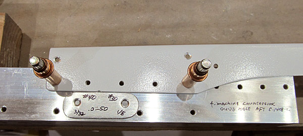 I skipped ahead just a little and machine countersunk the bottoms of the (C-01408-L and C-01408-R) left and right forward canopy rail bases. I did this because in step five, on page 38-09, referencing figure one, they will be rivited to the left and right forward canopy frame assemblies with AN426AD4-4 rivets. |
 This is the (C-01408-R) right forward canopy rail base and just like the left one it is being machine countersunk to receive a #30 dimpled .025" skin. I cleco the countersunk holes as I move along. |
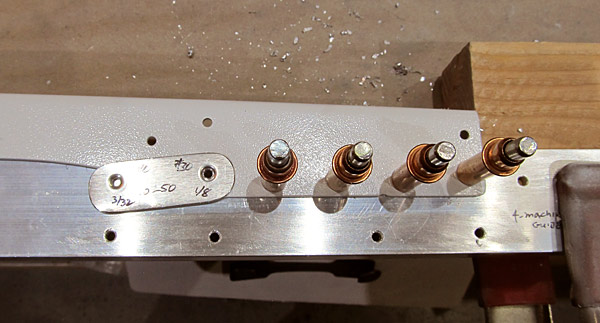
 The machine countersinking is progressing... |
 As per step ten, on page 38-16, referencing page 38-17 figure two, the bottoms of the (C-01408-L and C-01408-R) left and right forward canopy rail bases were machine countersunk to receive the head of AN426AD4-4 rivets and to receive a .025" dimpled skin. |
 As per step one, on page 38-09, referencing figure one, clecoed and then riveted the left and right hinge assemblies to the (C-01402-L and C-01402-R) left and right forward canopy frames using a 3x rivet gun equipped with a 10 1/2" inch, 1/8" cupped extension, setting AN470AD4-4 rivets making sure that the manufactured heads faced forward. |
 As per step two, on page 38-09, referencing figure one, clecoed the (C-01415-L and C-01415-R) left and right forward intercostals and the (C-01416-L and C-01416-R) left and right intercostals to the (C-01403-L and C-01403-R) left and right mid canopy frames. |
 I wanted to get started on deburring the (C-01417) canopy frame close-out before I riveted the intercostals to the mid canopy frames....(only because the rivets were at our hangar which is over twenty miles away). |
 After deburring all of the holes, I clamped the (C-01417) canopy frame close-out to the bench and deburred the edges with a small file. |
 After the filework was done I polished the edges of the (C-01417) canopy frame close-out with fine sandpaper. |
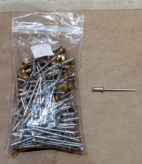 Remember the rivets that were at the hangar over twenty miles away? Well here they are bag 3218....LP4-3 rivets will be used to secure the intercostals to the mid canopy frames. |
 These little wedges are really handy when setting blind rivets in tight spaces. |
 That handy little rivet wedge offsets the rivet gun just enough to squarely set the rivet! |
 As per step two, on page 38-09, referencing figure one, the (C-01415-L and C-01415-R) left and right forward intercostals and the (C-01416-L and C-01416-R) left and right aft intercostals were riveted to the (C-01403-L and C-01403-R) left and right mid canopy frames with LP4-3 blind rivets using our hand rivet gun. |
 As per step three, on page 38-09, referencing figure one, clecoed the left canopy hinge assembly to the (C-01403-L) left mid canopy frame and then clamped this to the workbench so that they could be riveted together with AN470AD4-4 rivets which were set using our pneumatic squeezer. |
 As per step four, on page 38-09, referencing figure one, I clecoed the (C-01415-L and C-01415-R) left and right forward intercostals to the (C-01402-L and C-01402-R) left and right forward canopy frames and riveted them together with AN470AD4-4 rivets set with our pneumatic rivet squeezer. |
 This is the right forward canopy frame. |
 This is the side view of the right forward canopy frame. |
 This is the side view of the left forward canopy frame. |
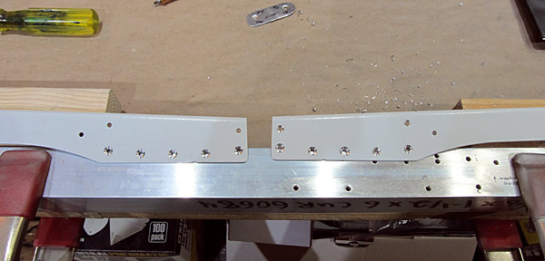
 As per step five, on page 38-09, referencing figure one, I clecoed the (C-01408-L and C-01408-R) left and right forward canopy rail bases to the (C-01402-L and C-01402-R) left and right forward canopy frames and to the (C-01403-L and C-01403-R) left and right mid canopy frames. |
 This is the Right Forward Canopy Frame Assembly. |
 This is just a inside view of the rivets that were set to attach the (C-01408-L) left forward canopy rail to the (C-01402-L) left forward canopy frame and the (C-01403-L) mid canopy frame, now collectively known as the Left Forward Canopy Frame Assembly. |
 I mixed up some SPI, Southern Polyurethanes Inc., (6610-4) gray epoxy primer to touch up the heads of the AN470AD4-4 rivets that were set. |
 I top coated the AN470AD4-4 rivets with Stewart Systems E5301 EkoCrylic smoke gray paint. |
 As per step six, on page 38-09, referencing figure one, I clecoed the (C-01428) frame splices to the left and right forward canopy frame assemblies. |
 There are two (C-01428) frame splices, this photograph shows them connected to the forward and mid canopy frames from overhead. |
 The joined left and right forward canopy frame assemblies are positioned on their backs for the next step.... |
 As per step seven, on page 38-09, referencing figure one, the (C-01442A) forward canopy fixture was clecoed to the (C-01408-L and C-01408-R) left and right forward canopy rail bases. |
 Here is what it all looks like when the (C-01442A and C-01442B) forward and mid canopy fixtures are clecoed in place. |
 The whole assembly was carefully flipped over and as per step eight, on page 38-09, referencing figure one, the (C-01406-L and C-01406-R) left and right forward canopy rails and the (C-01418) canopy skin was clecoed to the left and right forward canopy frame assemblies starting in the center and working symmetrically outboard clecoing every other hole. |
 Here is what it all looks like from the side.... |
 Once again the assembly was carefully flipped over and as per step nine, on page 38-09, adequate fluting was checked between the flanges of the (C-01402-L and C-01402-R) left and right forward canopy frame, the (C-01403-L and C-01403-R) left and right mid canopy frames, and the skin of the (C-01418) canopy skin. |
 No gaps here... |
 No gaps here... |
 No gaps here... |
 As per step one, on page 38-10, referencing figure one, the holes in the flanges of the (C-01417) canopy frame close-out were dimpled using a 1/8" dimple die set using our hand squeezer. |
 The canopy assembly has been on it's back and now has to leveled and stabilized so that the (C-01417) canopy frame close-out can be clecoed in place. |
 As per step five, on page 38-10, the (C-01417) canopy frame close-out was clecoed into position, clecos added to each available hole in the forward canopy frame assemblies. |
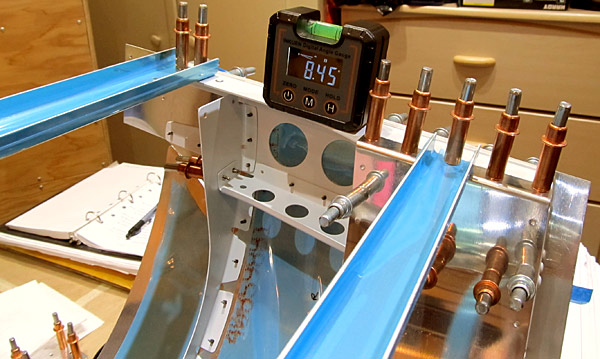 The canopy assembly was re-checked for level and stability and as per step seven, on page 38-10, a check was made for canopy twist using a digital level. |
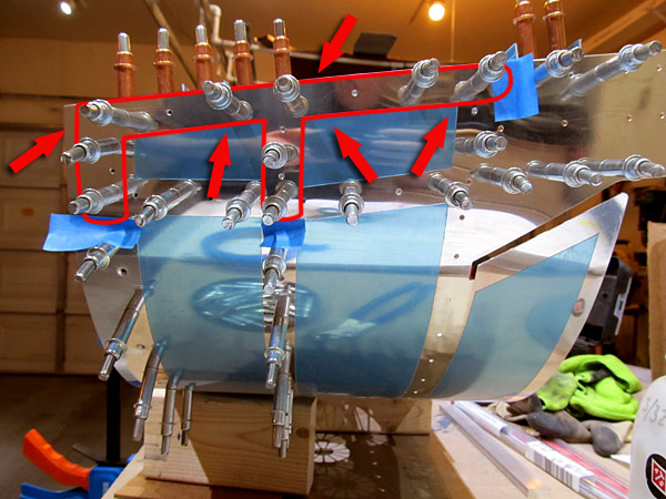 As per step eight, on page 38-10, referencing figure two, the holes outlined in red in this photograph were final #40 drilled and re-clecoed. |
 As per step nine, on page 38-10, referencing figure three, the (C-01404-L and C-01404-R) left and right support flanges were clecoed to the (C-01418) canopy skin and the (C-01416-L and C-01416-R) left and right aft intercostals. |
 As per step ten, on page 38-10, referencing figure three, the (C-01404A) small support flange splice was clecoed to the (C-01404-L and C-01404-R) left and right support flanges. |
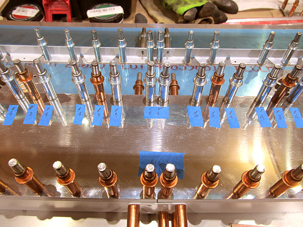
 As per step eleven, on page 38-10, double checked the canopy assembly for twist and made adjustments as necessary. The individual holes that needed to be drilled on the (C-01417) canopy frame close-out were marked to be drilled 1/8" or 3/32" according to detail A and figure three, using blue tape beside each hole. |
 As per step twelve, on page 38-10, referencing figure three and detail A, match and final drilled the holes in the (C-01417) canopy frame close-out, beginning in the center and working symmetrically outboard. |
 That's a lot of clecos! |
 As I stated earlier, it is hard to know when to paint the parts in section 38. When the tip up canopy is open everything will be seen so I feel that all needs to be painted but do you paint it after the frame is all put together, or do you paint the parts individually as the frame is being built? |
 I primed the (C-01417) canopy frame close-out with Southern Polyurethane Incorporated (SPI) 6610-4 gray epoxy primer. |
 I top coat painted the(C-01417) canopy frame close-out with Stewart Systems E5301 EkoCrylic smoke gray paint. |
 As per step one, on page 38-11, referencing figure one, the (C-01409) canopy rail angles were separated into two parts; (C-01409-L and C-01409-R) left and right canopy rail angles. |
 I used a bandsaw to separate the canopy rail angles but even with a fine toothed metal cutting blade it is still going to take a fair amount of filing to debur these pieces. |
 I edge deburred the (C-01409-L and C-01409-R) left and right canopy rail angles using a small file. |
 This is what the edges look like after deburring them with the small file. |
 All of the edges of the (C-01409-L and C-01409-R) left and right canopy rail angle edges have been sanded with fine sandpaper and polished. |
 The surfaces of the (C-01409-L and C-01409-R) left and right canopy rail angles have been scuffed with maroon and gray Scotch-Brite™ pads in preparation for priming. |
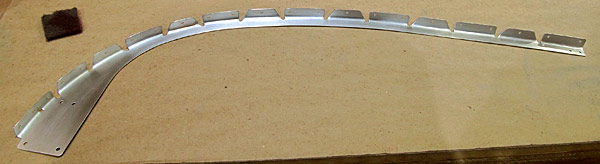
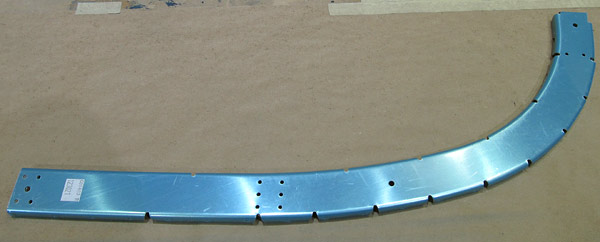
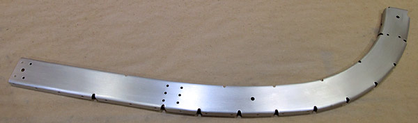
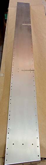
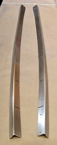
 The (C-01407-L and C-01407-R) left and right aft canopy rails are next to be deburred but first I have to remove the protective blue vinyl. |
 All of the holes were deburred in the (C-01407-L and C-01407-R) left and right aft canopy rails and the parts were washed with acetone to remove the red ink stamped on the back side. |
 I like to clamp the aft canopy rails to a piece of angle to make it easier to debur the edges first with a small fine toothed file. |
 Here you can see what the edges of the (C-01407-L) aft canopy rail looks like before and after it has been deburred with a small file. |
 After the file work is done I like to sand and polish the edges with fine sandpaper. |
 As per step two, on page 38-11, referencing figure one, I used a single cleco to attach the (C-01409-L and C-01409-R) left and right aft canopy rail angles to the (C-01407-L and C-01407-R) left and right aft canopy rails. |
 Here is an overhead view of the (C-01409-L and C-01409-R) left and right aft canopy angles attached to the (C-01407-L and C-01407-R) left and right aft canopy rails by single clecoes in the middle. |
 This is probably a better overhead shot...Take notice of the bend in the (C-01409-L and C-01409-R) left and right aft canopy rail angles. |
 As per step three, on page 38-11, referencing figure two, the purpose to having these parts single clecoed together is so that the location of the pre-punched holes in the (C-01407-L and C-01407-R) left and right aft canopy rails could be marked onto the (C-01409-L and C-01409-R) left and right aft canopy rail angles which I did using a Sharpie. you can see the small circles on the angle at the bottom of this photograph. |
 After the location of the pre-punched holes were marked onto the (C-01409-L and C-01409-R) left and right aft canopy rail angles, everything was taken apart (step four) so that the angles could be straightened. |
 As per step five, on page 38-11, referencing figure one, the (C-01409-L and C-01409-R) left and right aft canopy rail angles were fluted as required to reduce the bowed down angles due to the manufacturing process. The flanges should rest on a flat surface, in this case I am using a level for that flat surface. |
 In this photograph you can see the small reference holes drawn by the Sharpie pen and the flutes required to straighten the aft canopy rail angles. |
 When fluting the (C-01409-L and C-01409-R) left and right aft canopy rail angles, the fluting pliers can leave marks in the aluminum so I am sanding those marks out with 600 grit sandpaper in preparation for painting. |
 This looks a lot better! The flute marks are removed and should not be visible after painting. |
 The (C-01409-L and C-01409-R) left and right aft canopy rail angles are ready for priming. |
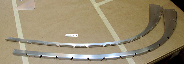
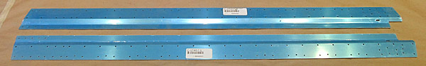
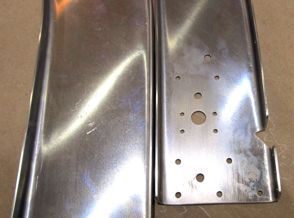
 These are the (C-01427-L and C-01427-R) left and right aft canopy rail flanges, they connect the front canopy section to the aft canopy frame. |
 The edges of the (C-01427-L) left aft canopy flange and all of the holes were deburred with a small file. Final sanding of the edges with up to 600 grit sandpaper will come next.... |
 The edges of the (C-01427-R) right aft canopy flange and all of the holes were deburred with a small file. Final sanding of the edges with up to 600 grit sandpaper will come next.... |
 The edges of the (C-01427-L and C-01427-R) left and right aft canopy rail flanges were polished with fine sandpaper in preparation for priming. |
 The surfaces of the (C-01427-L) left aft canopy rail flange were scuffed with a maroon Scotch-Brite™ pad. |
 The surfaces of the (C-01427-R) right aft canopy rail flange were scuffed with a maroon Scotch-Brite™ pad and then both of the (C-01427-L and C-01427-R) left and right aft canopy rail flanges were scuffed with a gray Scotch-Brite™ pad in preparation for priming. |
 As per step six, on page 38-11, referencing figure three, the three indicated holes were machine countersunk on the aft side of the (C-01427-L) left aft canopy rail flange to fit the head of a AN426AD4 rivet. |
 As per step six, on page 38-11, referencing figure three, the three indicated holes were machine countersunk on the aft side of the (C-01427-R) right aft canopy rail flange to fit the head of a AN426AD4 rivet. |
 Now it is time to machine countersink the four holes indicated in figure three to fit the head of a AN426AD3 rivet. |
 As per step six, on page 38-11, referencing figure three, all of the indicated holes have been machine countersunk on the aft side of the (C-01427-L and C-01427-R) left and right aft canopy rail flanges. |
 As per step one, on page 38-12, referencing figure one, the (C-01409-L and C-01409-R) left and right aft canopy rail angles are clecoed to the (C-01427-L and C-01427-R) left and right aft canopy rail flanges. |
 As per step two, on page 38-12, referencing figure one, final drilled #40 the holes common to the (C-01409-L) left aft canopy rail angle into the (C-01427-L) left right aft canopy rail flange. |
 As per step two, on page 38-12, referencing figure one, final drilled #40 the holes common to the (C-01409-R) right aft canopy rail angle into the (C-01427-R) right aft canopy rail flange. |
 As per step three, on page 38-12, referencing figure one, match drilled #40 the (additional) two holes in the (C-01427-L and C-01427-R) left and right aft canopy rail flanges into the (C-01409-L and C-01409-R) left and right aft canopy rail angles. |
 The additional two holes have been match drilled into the (C-01409-L and C-01409-R) left and right aft canopy rail angles. |
 As per step four, on page 38-12, referencing figure one, the bottom holes of the (C-01409-L and C-01409-R) left and right aft canopy rail angles need to be machine countersunk on the bottom sides to flush fit the heads of AN426AD3 or AN426AD4 rivets. |
 This is the (C-01409-L) left aft canopy rail angle. |
 After the holes in the (C-01409-L and C-01409-R) left and right aft canopy rail angles were machine countersunk, they were washed with soap and water and then rinsed. |
 The (C-01409-L and C-01409-R) left and right aft canopy rail angles are ready for priming.... |
 The (C-01409-L and C-01409-R) aft canopy rail angles and the (C-01427-L and C-01427-R) left and right aft canopy rail flanges were primed with Southern Polyurethanes Incorporated (SPI) 6610-4 gray epoxy primer. |
 I skipped ahead to step one, on page 38-13, referencing figure one, to begin fabricating the (C-01437-L and C-01437-R) left and right canopy handles. |
 I started out by laying out two, 2" lines in the aluminum angle to be cut out on the bandsaw. |
 The 2" pieces were cut out using our bandsaw. |
 Using a small file, the shape of the (C-01437-L and C-01437-R) left and right canopy handles were created based on the dimensions specified in figure one, on page 38-13. |
 I sanded the (C-01409-L and C-01409-R) left and right aft canopy rail angles and the (C-01427-L and C-01427-R) left and right aft canopy rail flanges with 600 grit sandpaper in preparation for topcoat painting. |
 As per step five, on page 38-12, referencing figure one, I clecoed (but did not rivet) the (C-01409-L and C-01409-R) left and right aft canopy rail angles to the (C-01427-L and C-01427-R) left and right aft canopy rail flanges in preparation for riveting.....(of course the rivets to be used are back at the hangar)...uuugggh!! |
 Back to the (C-01437-L and C-01437-R) left and right canopy handles, I am super fine sanding these so that they can be polished. |
 I am using Nuvite NuShine IIA repolish and touch up for the first application of polish and then Nuvite NuShine IIS mirror finish for the final stage of polishing. |
 This is the final polish using Nuvite NuShine IIS mirror finish. |
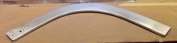
 As per step five, on page 38-12, referencing figure one, I riveted the (C-01409-L and C-01409-R) left and right aft canopy rail angles to the (C-01427-L and C-01427-R) left and right aft canopy rail flanges making sure that the dome heads of the AN470AD3 and AN470AD4 rivet types were on the upper side of the (C-01427-L and C-01427-R) left and right aft canopy rail flanges. |
 This is the upper side. |
 This is the bottom side. |
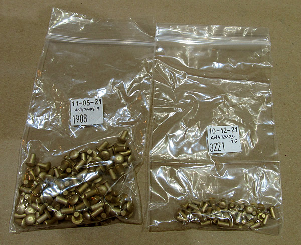 The rivets used were AN470AD3-3.5 and AN470AD4-4 |
 The (C-01409-L and C-01409-R) left and right aft canopy rail angles and the (C-01427-L and C-01427-R) left and right aft canopy rail flanges were re-primed to cover the newly set rivets. |
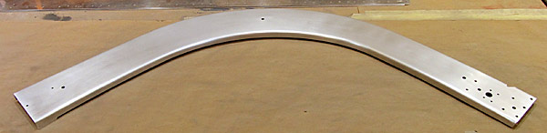
 The (C-01409-L and C-01409-R) left and right aft canopy rail angles and the (C-01427-L and C-01427-R) left and right aft canopy rail flanges were painted with Stewart Systems E5301 EkoCrylic smoke gray paint. |
 The protective blue vinyl was removed from the inner side of the (C-01418) canopy skin in preparation for priming. |
 The inner side of the (C-01418) canopy skin was scuffed with maroon and gray Scotch-Brite™ pads in preparation for priming. |
 After cleaning the top side half of the (C-01418) canopy skin with acetone and wiped down with Southern Polyurethanes Incorporated (SPI) 700-1 wax and grease remover, the top side half of the (C-01418) canopy skin was masked off in preparation for priming. |
 The aft ends of the (C-01409/ C-01427) assemblies were masked off and then painted with Stewart Systems E5465 EkoCrylic royal blue paint. |
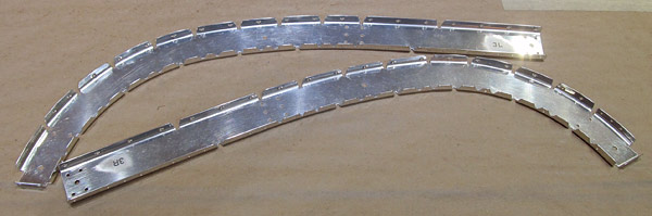
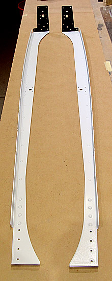
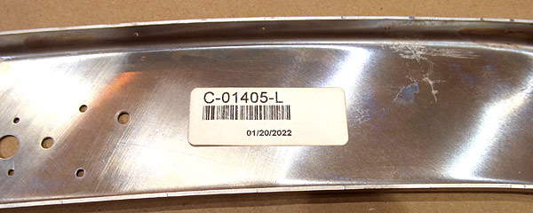
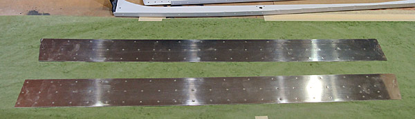
 Edge deburring begins on the (C-01405-L and C-01405-R) left and right aft canopy frames using a small file. |
 You can see that the edges are kind of rough... |
 The edges of the (C-01405-L and C-01405-R) left and right aft canopy frames have been deburred, as well as all of the holes. |
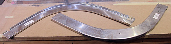
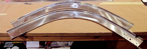
 I polished the edges of the (C-01405-L and C-01405-R) left and right aft canopy frames with fine sandpaper. This is how they will look when joined together with rivets. |
 Here is a closer look at the edges after they have been polished... |
 The surfaces of the (C-01405-R) right aft canopy frame have been scuffed with maroon and gray Scotch-Brite™ pads in preparation for priming. |
 The surfaces of the (C-01405-L) left aft canopy frame have been scuffed with maroon and gray Scotch-Brite™ pads in preparation for priming. |
 Here are both halves of the aft canopy frames scuffed with maroon and gray Scotch-Brite™ pads prepared for priming. |
 Here I am priming the inner side of the (C-01418) canopy skin with Southern Polyurethanes Incorporated (SPI) 6610-4 gray epoxy primer. |
 Here I am topcoating the inner side of the (C-01418) canopy skin with Stewart Systems E5301 EkoCrylic smoke gray paint. |
 Here I am priming the (C-01405-L and C-01405-R) left and right aft canopy frames with Southern Polyurethanes Incorporated (SPI) 6610-4 gray epoxy primer. |
 I am sanding the (C-01405-L and C-01405-R) left and right aft canopy frames with 600 grit sandpaper in preparation for topcoat paint. |
 The Stewart Systems EkoCrylic paints adhere a little better when the surfaces are sanded with 600 grit sandpaper, it's a mechanical bonding paint. |
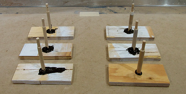 I fashioned these short mini paint stands to paint the aft canopy frames because I am going to paint the inner surfaces first and then the outer surfaces later. |
 This is how the stands will work when the frames are sitting on the table inside of the paint booth. |
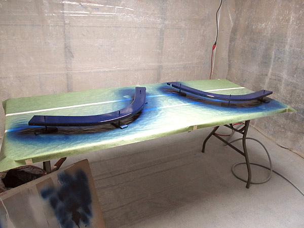
 I have the (C-01405-L and C-01405-R) left and right aft canopy frames sitting on the table in the paint booth on their mini stands ready to paint with Stewart Systems E5465 EkoCrylic royal blue paint. |
 This is the Stewart Systems E5465 EkoCrylic royal blue paint being applied to the inner halves only in this session. |
 The royal blue paint is the same color that I painted the main roll bar with. |
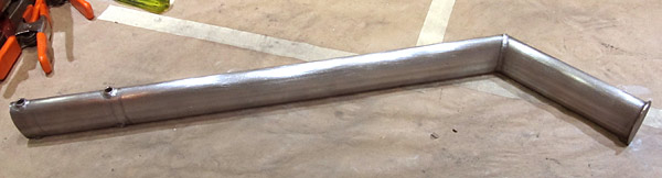
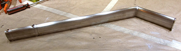
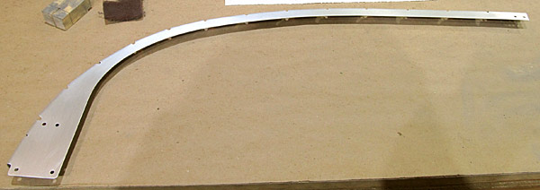
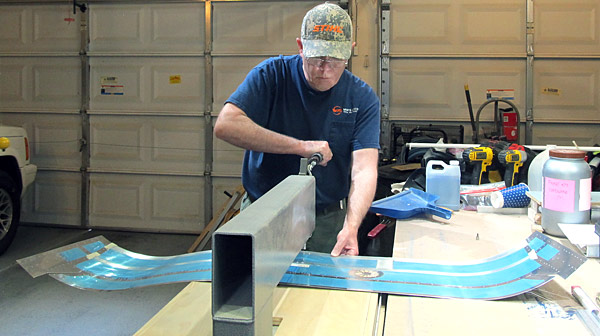
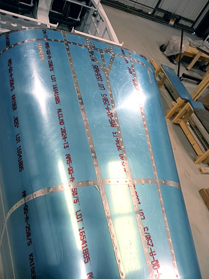
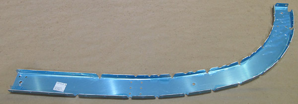
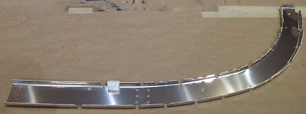
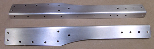
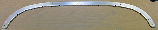
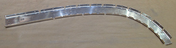
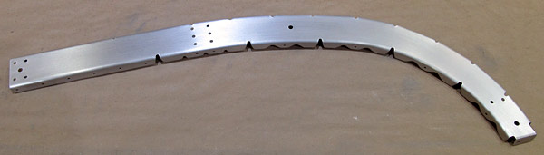
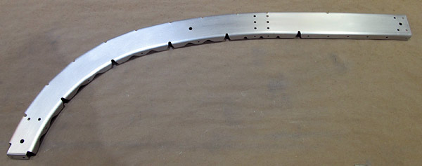
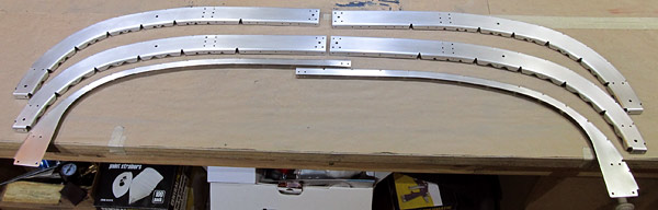
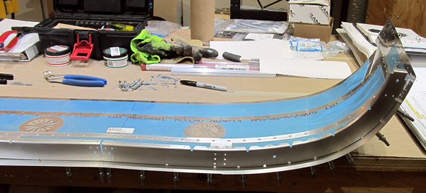
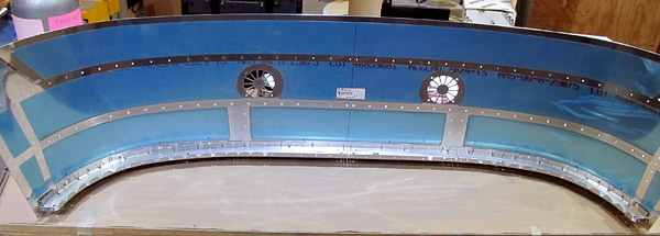
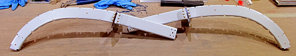
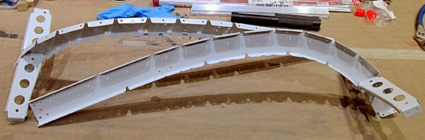
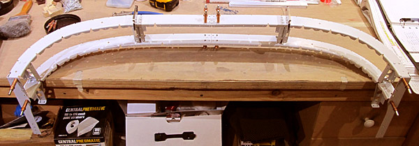
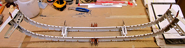
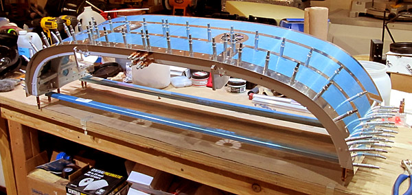
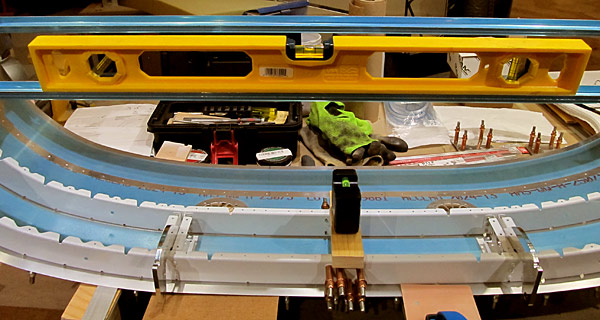
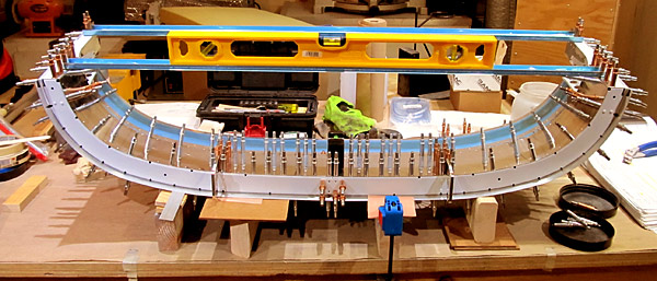
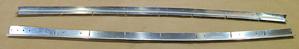
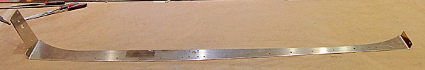
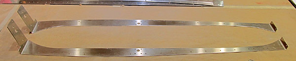
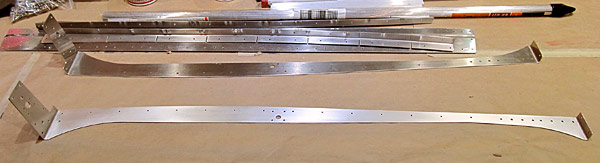
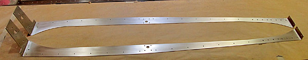
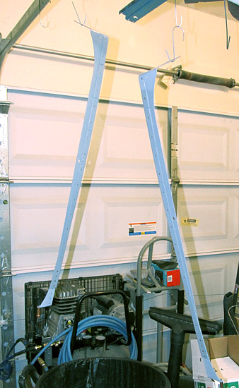
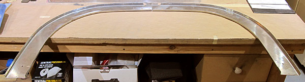
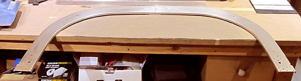
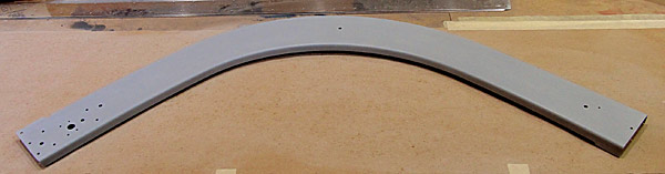
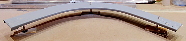
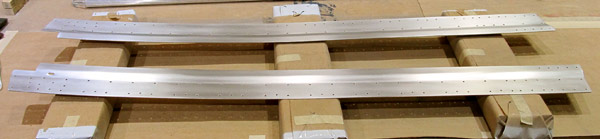
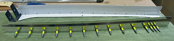
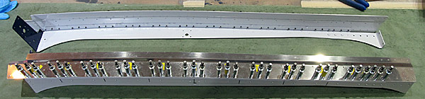
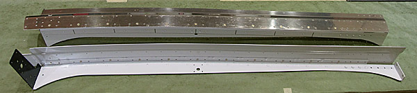
 As per step six, on page 38-12, the (C-01407-L and C-01407-R) left and right aft canopy rails were formed/ shaped to closely match the curve of the fuselage aft of the sixteen inch mark referenced in figure one. |
 Here's another view that shows how much the fuselage curves as you approach where the rollbar is. |
 This is the Stewart Systems E5465 EkoCrylic royal blue paint being applied to the (C-01405-L and C-01405-R) left and right aft canopy frames outer halves. |
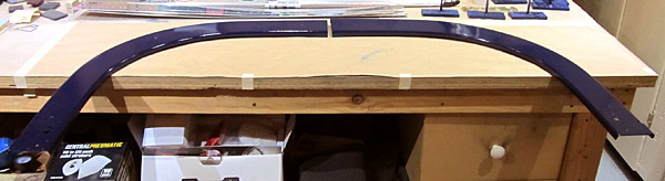 This is the (C-01405-L and C-01405-R) left and right aft canopy frames as they will appear when they are joined.... |
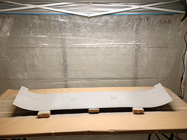
 The (C-01407-L and C-01407-R) left and right aft canopy rails were scuffed with maroon and gray Scotch-Brite™ pads in preparation for priming. |
 The outer surfaces of the (C-01407-L and C-01407-R) left and right aft canopy rails were masked off because the outside surfaces are not going to be painted. |
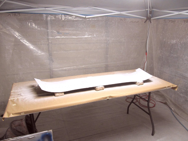
 The (C-01407-L and C-01407-R) left and right aft canopy rails are being primed with Southern Polyurethanes Incorporated (SPI) 6610-4 gray epoxy primer. |
 Here are the primed (C-01407-L and C-01407-R) left and right aft canopy rails. |
 Before I topcoat the (C-01407-L and C-01407-R) left and right aft canopy rails, I am sanding them with 600 grit sandpaper. |
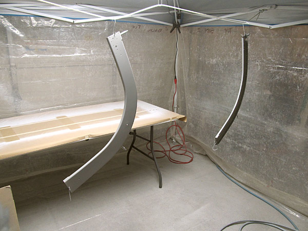
 The (C-01407-L and C-01407-R) left and right aft canopy rails were topcoated with Stewart Systems E5301 EkoCrylic smoke gray paint. |
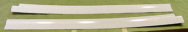
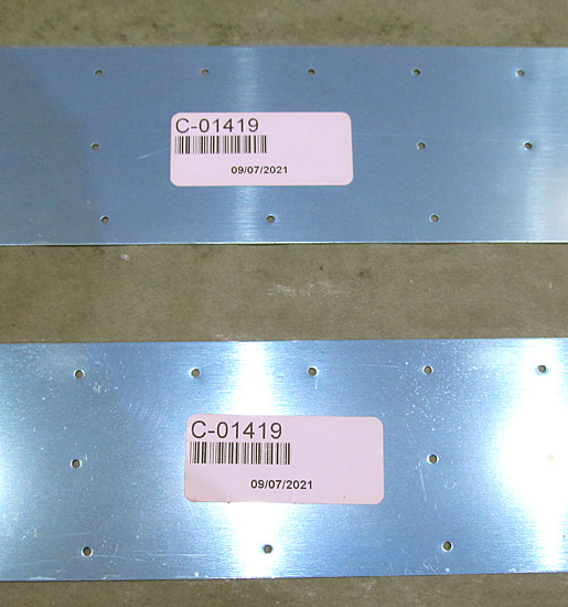 I began the debur process on the (C-01419-L and C-01419-R) left and right canopy side skins. Of course the first step is always to peel off the protective blue vinyl... |
 The edges and all of the holes were deburred and polished smooth with 600 grit sandpaper. |
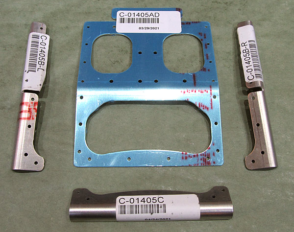 These are the parts that make up the Canopy Handle Assembly: |
 As per step one, on page 38-14, referencing figure one, I separated the (C-01405A) canopy handle web and the (C-01405D) aft canopy frame splice using a hand held saw. |
 All of the edges and holes of the canopy handle assembly were deburred using a small file. |
 My small round file makes deburring the inner "circles" of the (C-01405A) canopy handle web go easier of course as usual all of the edges will be polished soon... |
 The edges were polished with up to 600 grit sandpaper. |
 I clecoed the canopy handle assembly together so that I can scuff only the surfaces of the assembly that were going to be painted. |
 The parts were disassembled and then finish scuffed with Scotch-Brite™ maroon and gray pads. |
 As per step three, on page 38-14, referencing figure two, all of the canopy handle assembly parts were clecoed together again and riveted where indicated in figure two. |
 I have heard some stories about how uncomfortable the grip on the canopy handle assembly is so I decided to fabricate a custom grip for our canopy handle assembly. |
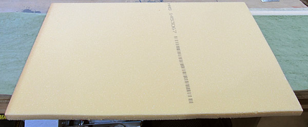
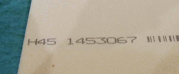 I bought the Type H45 Divinylcell foam at Aircraft Spruce. I ordered the 15"x26" sheet. |
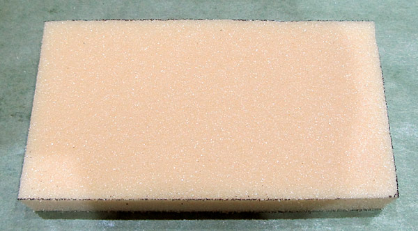 I cut a 4-3/4"x 2-9/16" block out to construct the grip from, the foam is firm but easily cut and will be easy to carve with a rasp or file. |
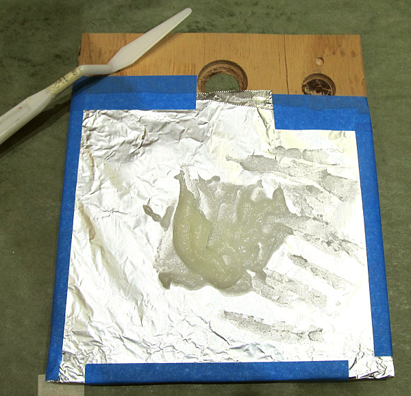
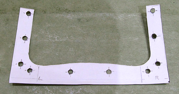 This is the template I used to form the grip shape into the Divinylcell with. |
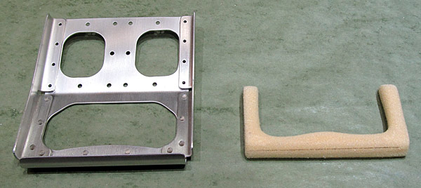 This is the shape of the canopy handle grip, it was easily shaped using a rasp, it is firm and not terribly fragile so it can take the handling without fear of breaking it. |
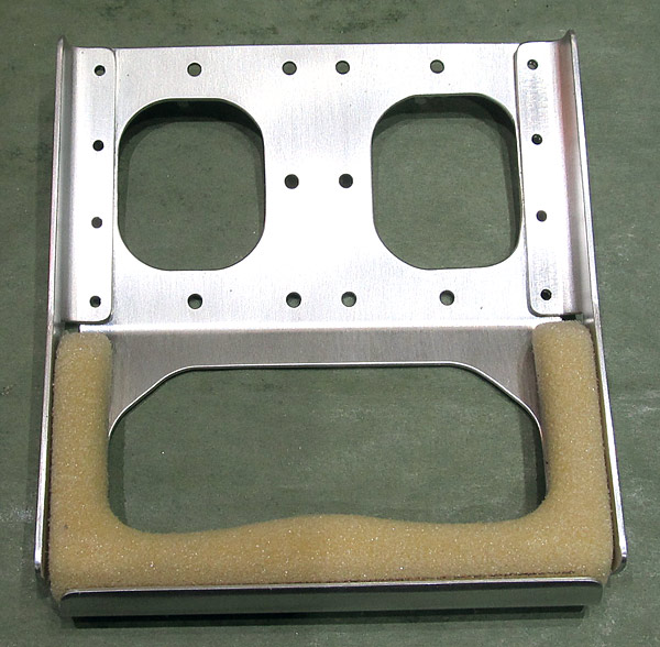 Here is the handle in place on the canopy handle assembly. Don't forget to allow for the addition of resin and microballoons which will come in the next steps of the fabrication process. |
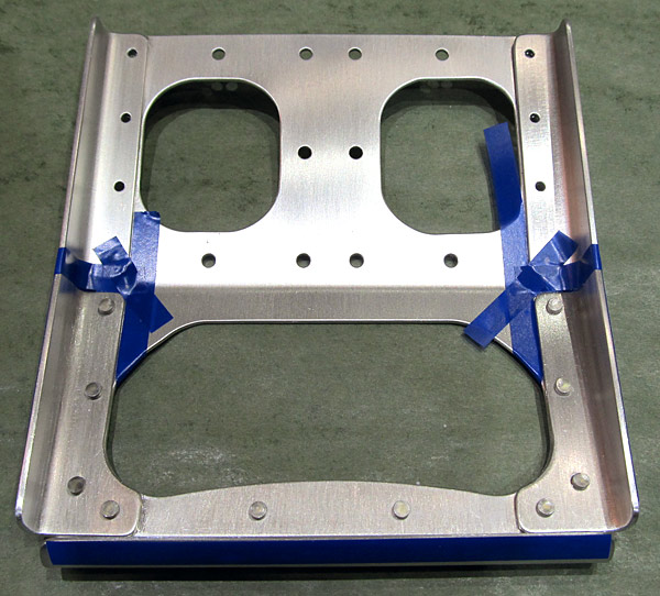 Next comes the messy part...I masked off the areas and edges of the canopy handle assembly that I didn't want the cotton flox/resin mix to stick to. |
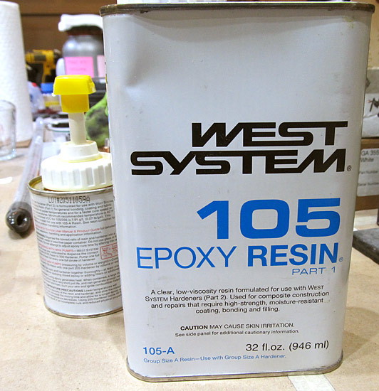 I used West Marine® 105 resin. I am going to mix this, plus the hardener, plus cotton flox to initially cover and set in place the divinylcell grip core. |
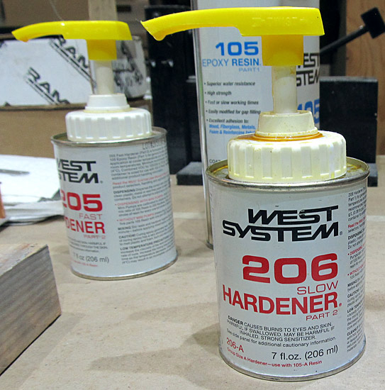 I used West Marine® 206 slow hardener so that I would have ample time to shape the cotton flox once it was applied. Cotton flox, I am told is pretty tough stuff once cured so hopefully doing some shaping while it is still "wet" might be a plus! |
 I mixed the resin and cotton flox to slightly thicker than toothpaste consistency. I am applying this to the canopy handle assembly with a pallette knife. |
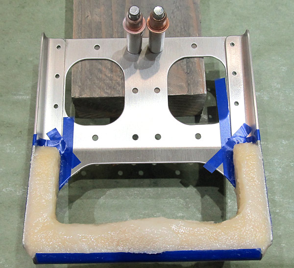 First, I laid down a bed of cotton flox mixture on the base and sides of the (C-01405B-L and C-01405B-L) left and right flange handles, and the (C-01405A) canopy handle web, for the divinylcell core to sit in, and then applied the cotton flox mixture to the remaining upper surfaces of the divinylcell grip core. |
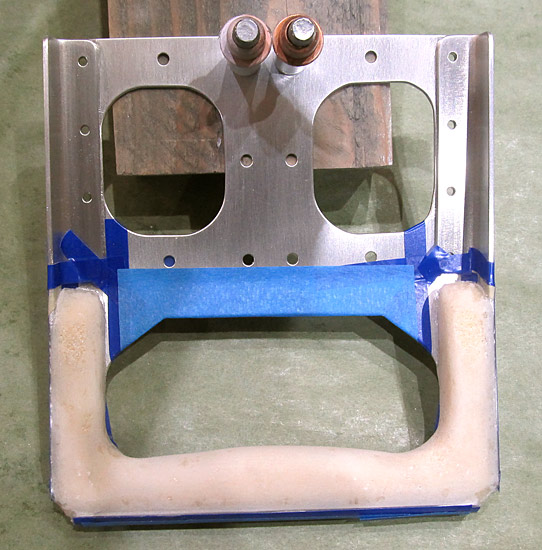 I sanded the cotton flox mixture that was applied to the canopy handle grip. It definitely is tough and requires course grip sandpaper (I used 100 grit) to get the grip sanded to where it would be ready for filling the surface with microballoons. |
 I mixed some West Marine® 105 resin, 205 hardener, and microballoons together and appiled it to the surface of the canopy handle grip. |
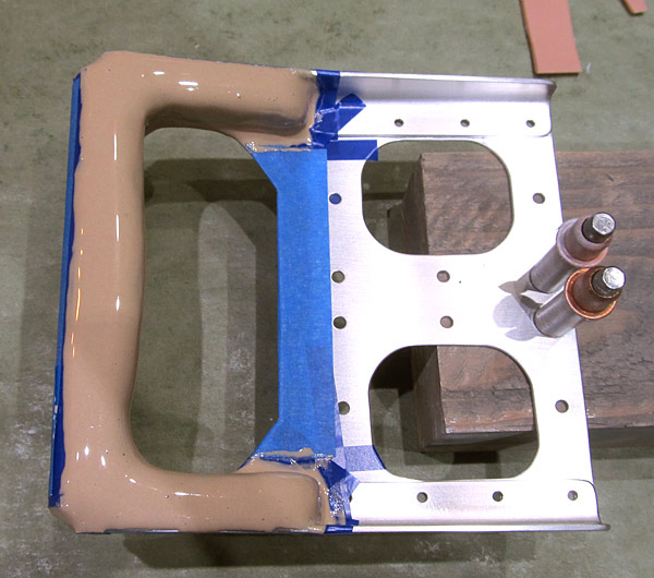
 I sanded the canopy handle grip with the microballoon filler with sandpaper starting with 220 grit sandpaper and stopped at 400 grit sandpaper. |
 I resanded the canopy handle grip for the second time, this time I finished with 600 grit sandpaper then wiped the canopy handle assembly with Southern Polyurethanes Incorporated (SPI) 700-1 wax and grease remover in preparation for priming. |
 I primed the canopy handle assembly with Southern Polyurethanes Incorporated (SPI) 6610-4 gray epoxy primer. |
 The canopy handle assembly was final sanded and wiped down in preparation for topcoat painting. |
 I topcoat painted the canopy handle assembly with U-Tech (U500) single stage gloss black paint. |
 I am sanding the top half of the canopy handle assembly so that it can be painted royal blue to match the color of the roll bar assembly. |
 I masked off the bottom half of the canopy handle assembly so that the top half can be painted royal blue. |
 The (C-01405D) aft canopy frame splice is ready to be painted royal blue. |
 The upper half of the canopy handle assembly and the (C-01405D) aft canopy frame splice were painted with Stewart Systems E5465 EkoCrylic royal blue paint. |
 I removed the masking tape from the canopy handle assembly after it was painted royal blue....yeah, there is some orange peel but that will be fixed soon! |
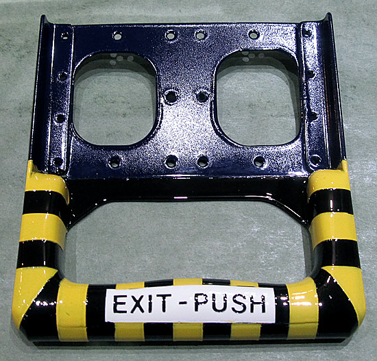
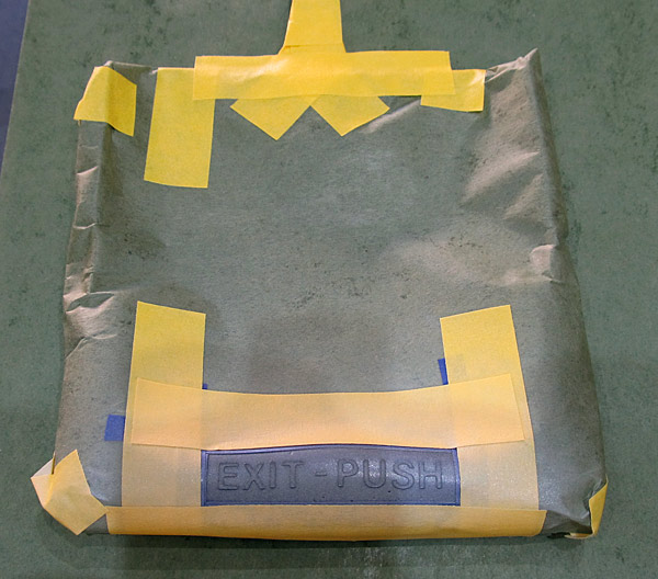 I masked off the canopy handle grip because I want to label it with a white strip with the instruction "EXIT-PUSH" which will be black lettered. |
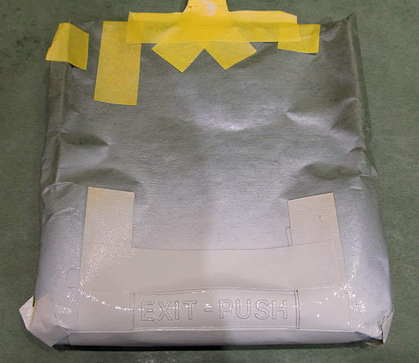 I painted the strip on the canopy handle grip with U-Tech(U500) single stage gloss white. |
 This is what the white strip with the instruction "EXIT-PUSH" looks like with the masking tape removed. |
 I masked off and primed the cockpit side of the (C-01444) canopy jettison handle with Southern Polyurethanes Incorporated (SPI) 6610-4 gray epoxy primer. |
 While the canopy jettison handle was drying as per step seven, on page 38-12, referencing figure one, I clecoed the (C-01407-L and C-01407-R) left and right aft canopy rails to the (C-01409-L and C-01409-R) left and right aft canopy rail angles. |
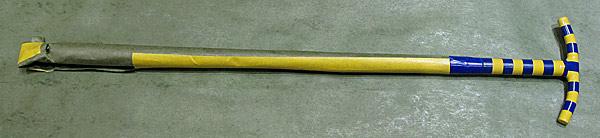
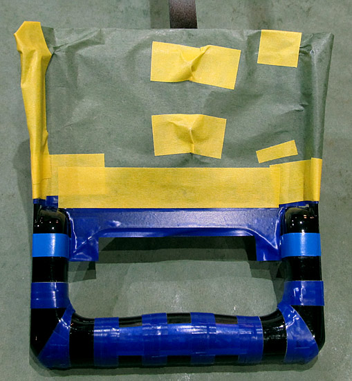 I masked off the canopy handle grip so that it would have stripes which will be painted yellow. |
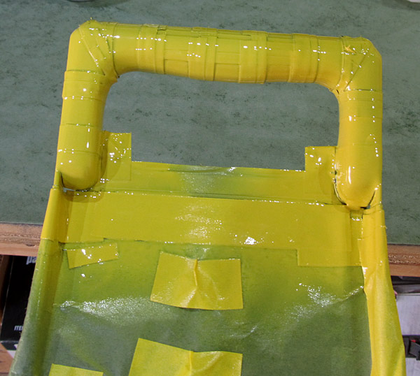 I painted the (C-01444) canopy ejection handle and this canopy handle grip with Krylon 1934 high gloss (urethane) tractor yellow paint. |
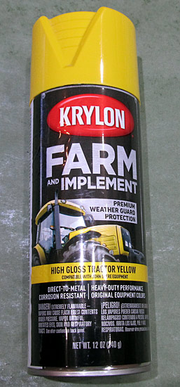 This is the Krylon 1934 high gloss (urethane) tractor yellow paint that I used. It is a very thin paint so it took a lot of coats to cover the black paint of the canopy handle grip and several coats to cover the gray primer paint on the canopy ejection handle too. |
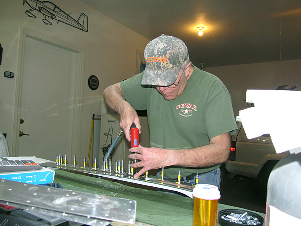 As per step eight, on page 38-12, referencing figure one, starting at the middle and working forward and aft equally, I match drilled #40 holes, and clecoed as drilling progressed, in the (C-01407-L and C-01407-R) left and right aft canopy rails into the (C-01409-L and C-01409-R) left and right aft canopy rail angles. |
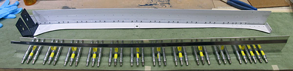 I removed the marked clecos from step seven and final #40 drilled them as well. |
|
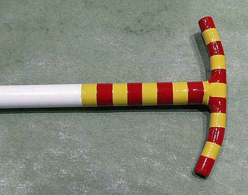
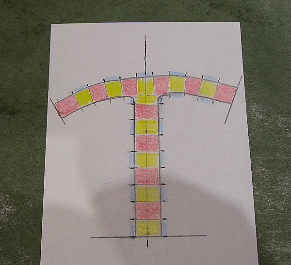 I want to paint red stripes onto the cockpit side of the (C-01444) canopy ejection handle so I made a template to help me lay out the lines onto the handle. |
 I masked off the stripes for the (C-01444) canopy ejection handle. |
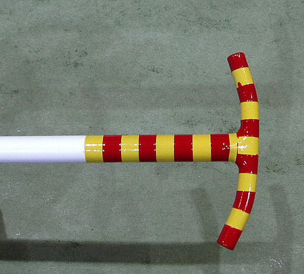 I painted the red stripes onto the (C-01444) canopy ejection handle. The Krylon 2720 high gloss (urethane) red pepper paint is also thin and I am going to have to clean up some areas that the paint seaped under the masking tape. |
 This is the Krylon 2720 high gloss (urethane) red pepper paint that I painted the stripes with. |
 As per step nine, on page 38-12, referencing figure one, removed the clecoed (C-01407-L and C-01407-R) left and right aft canopy rails from the (C-01409-L and C-01409-R) left and right aft canopy rail angles and deburred all holes. |
 As per step ten, on page 38-12, referencing figure one, machine countersunk the #40 sized holes that are marked (circled in figure one) into the (C-01407-L and C-01407-R) left and right aft canopy rails to fit the head of a AN426AD3-4 rivet. |
 I mounted the aft canopy rails to a block of wood which had holes pre-drilled in it that corresponded to the location of the marked holes that were to be countersunk. |
 As per step eleven, on page 38-12, referencing figure one, I re-clecoed the (C-01407-L and C-01407-R) left and right aft canopy rails to the (C-01409-L and C-01409-R) left and right aft canopy rail angles and inserted (but did not set) AN426AD3-4.5 rivets into the holes machine countersunk in step nine. (Circled holes in figure one.) |
 As per step twelve, on page 38-12, referencing figure one, the rivets were set joining the (C-01407-L and C-01407-R) left and right aft canopy rails to the (C-01409-L and C-01409-R) left and right aft canopy rail angles. |
 The canopy handle assembly custom grip was clear coat painted with SprayMax 2K Clear Glamour paint. |
 The (C-01444) canopy ejection handle was clear coat painted with SprayMax 2K Clear Glamour paint. |
|
 The upper half of the canopy handle assembly was sanded with 1500 grit sandpaper and buffed to remove orange peel in the royal blue paint. |
 As per step two, on page 38-14, the centerline of the (C-01405D) aft canopy frame splice was marked. |
 As per step two, on page 38-13, referencing figure two, the (C-01419-L and C-01419-R) left and right canopy side skins need to be clecoed to the left and right canopy rail assemblies. |
 As per step two, on page 38-13, referencing figure two, the (C-01419-L and C-01419-R) left and right canopy side skins were clecoed to the left and right canopy rail assemblies, clecoing every hole common to the canopy side skins and the canopy rail assemblies. |
 That's a lot of clecos! |
 Forty Nine Clecos per side! |
 As per step three, on page 38-13, referencing figure two, using the pilot hole in the (C-01437-L and C-01437-R) left and right canopy handles, they were clecoed to the left and right canopy rail assemblies. |
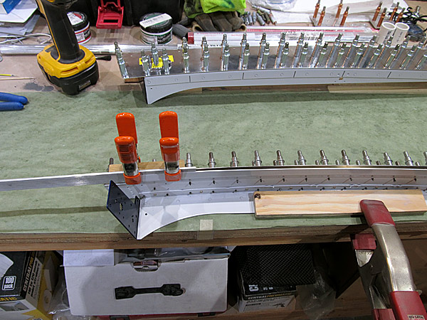 As per step four, on page 38-13, #40 holes were match drilled from the back side of the left and right canopy rail assemblies into the (C-01373-L and C-01437-R) left and right canopy handles, clecoing each hole as drilling progressed. |
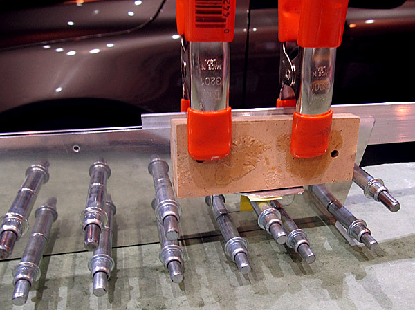 Here's a better view of the wood blocks keeping the canopy handles from rotating while being drilled. |
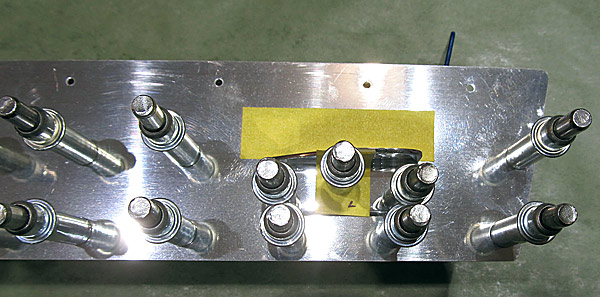 The canopy handle holes have been final #40 drilled. |
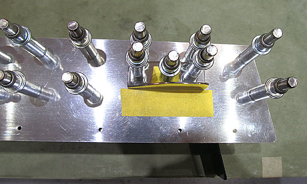 This is the right side. |
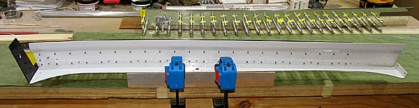 As per step five, on page 38-13, referencing figure two, final #40 drilled all the holes common to the (C-01419-L and C-01419-R) left and right canopy side skins and the left and right canopy rail assemblies. |
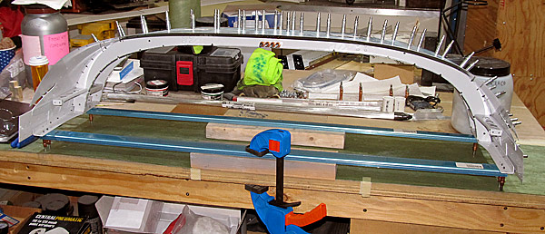 In anticipation of the next steps on page 38-13, the entire canopy frame assemblies were re-assembled using pages 38-09 and 38-10 as guides. |
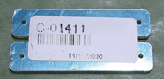 The (C-01411) canopy rail shim needs to be separated into two pieces. |
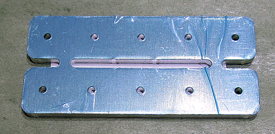 Here is the view from the back. |
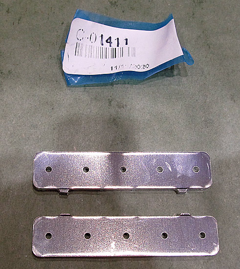 I separated this with a small bladed saw. |
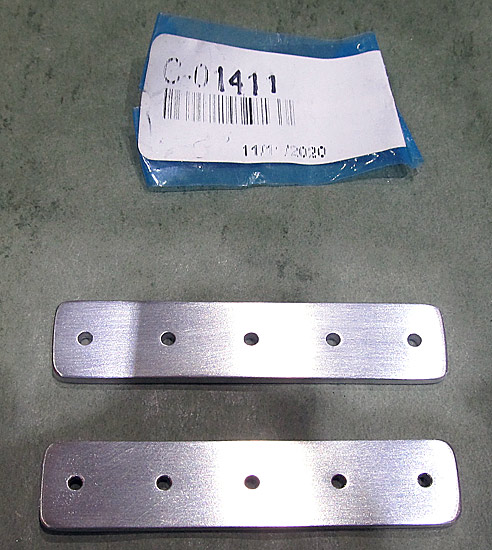 The (C-01411-L and C-01411-R) left and right canopy shims were edge deburred as well as were all the holes. |
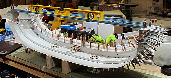 The canopy assembly was checked for twist, none was found. |
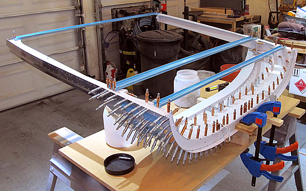 As per step seven, on page 38-13, the (C-01442B) mid canopy fixture was removed from the canopy assembly and then as per step, eight, on page 38-13, referencing figure three, the left and right canopy rail assemblies were slid between the (C-01406-L and C-01406-R) left and right forward canopy rails and the (C-01408-L and C-01408-R) left and right forward canopy rail bases as shown in figure three. |
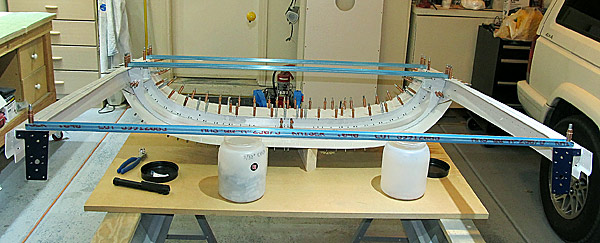 As per step nine, on page 38-13, referencing figure three, the (C-01442C) aft canopy fixture was clecoed to the canopy assembly. |
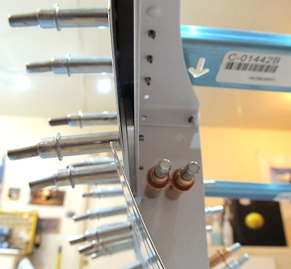 As per step ten, on page 38-13, referencing figure three, the (C-01411-L and C-01411-R) left and right canopy rail shims were slid and clecoed into place between the (C-01406-L and C-01406-R) left and right canopy rails and the left and right canopy rail assemblies. |
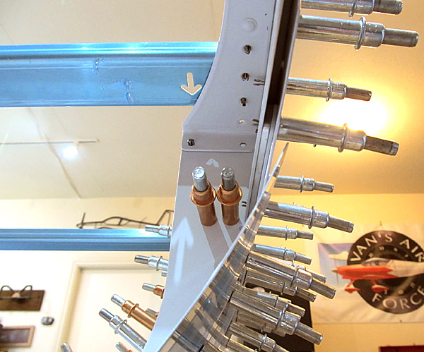 As per step ten, on page 38-13, referencing figure three, the (C-01411-L and C-01411-R) left and right canopy rail shims were slid and clecoed into place between the (C-01406-L and C-01406-R) left and right canopy rails and the left and right canopy rail assemblies. |
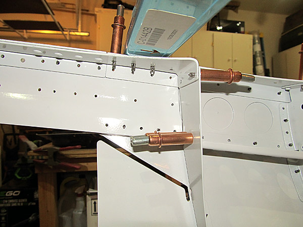 As per step eleven, on page 38-13, referencing figure three, final #40 drilled the holes in the canopy assembly called out in figure three, clecoing each as drilling progressed. |
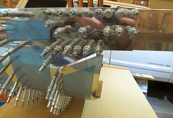 These are the clecoed #40 holes that were final drilled through the (C-01411-L and C-01411-R) left and right canopy rail shims and the (C-01406-L and C-01406-R) left and right canopy rails and the left and right canopy rail assemblies. |
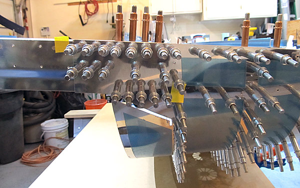 This is the left side of the canopy assembly. |
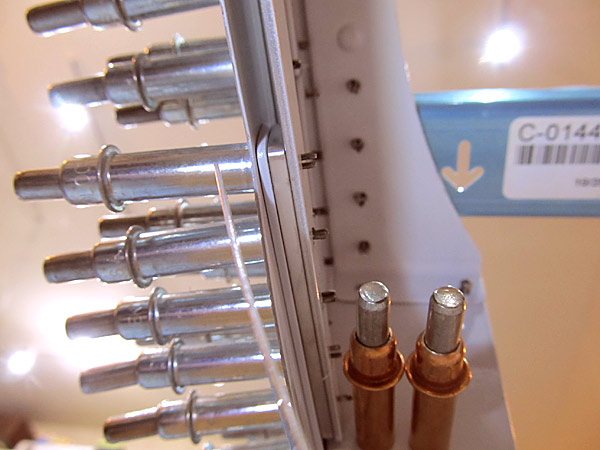 This is a close up view of the #40 drilled and clecoed (C-01411-R) right canopy rail shim. |
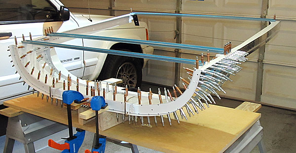 As per step twelve, on page 38-13, the canopy assembly will be disassembled and all holes drilled were deburred. |
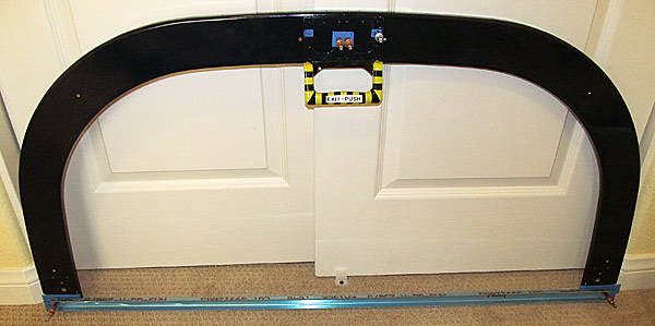 This is the first attempt to assemble all of the parts for the aft canopy frame as described in step four, on page 38-14, but there are some alignment issues. |
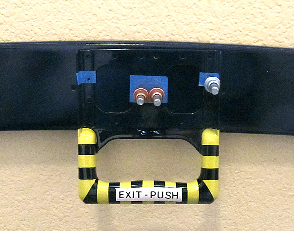 This is what I mean when I say not all of the holes in the canopy handle assembly are aligned. The open hole seen here will not allow a cleco to be installed. |
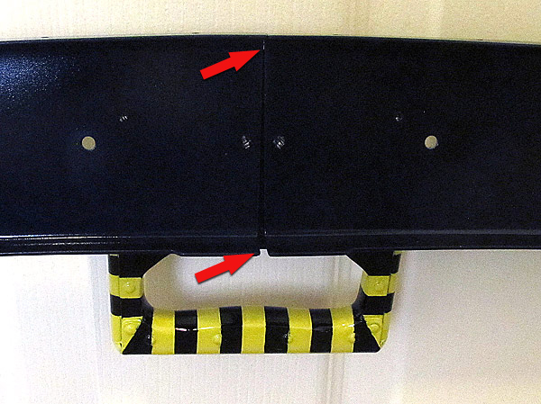 Take a look at how much of a gap there is on the back side view of the aft canopy frame joints. I need to go place this frame on the fuselage and custom fit it! |
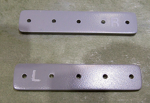 I primed the (C-01411-L and C-01411-R) left and right canopy rail shims with Southern Polyurethanes Incorporated (SPI) 6610-4 gray epoxy primer. |
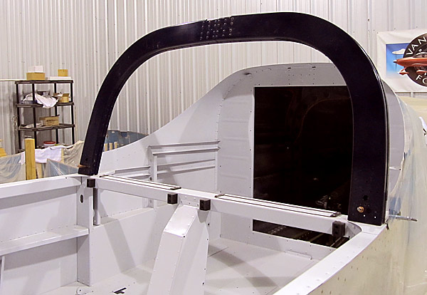 Well, I've been holding off installing the roll bar assembly for awhile so that I could have access to the aft tailcone section but I'm going to install it now so that I can move forward on the canopy frame assembly. |
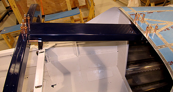 I clecoed the (F-01432A) roll bar brace to the roll bar assembly and to the (F-01406C) bulkhead assembly per figure one on page 37-07. |
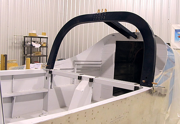 This is what it looks like before the riveting starts... |
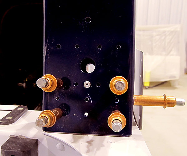 As per step five, on page 37-06, referencing figure one I riveted one CS4-4 rivet per side to the roll bar assembly as shown in figure one. |
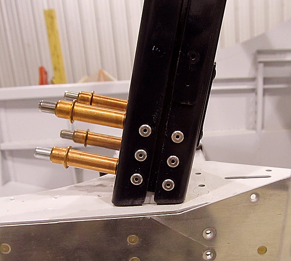 As per step six, on page 37-06, referencing figure one, I riveted the side flanges of the roll bar assembly to the (F-01431D) roll bar base with LP4-5 rivets. |
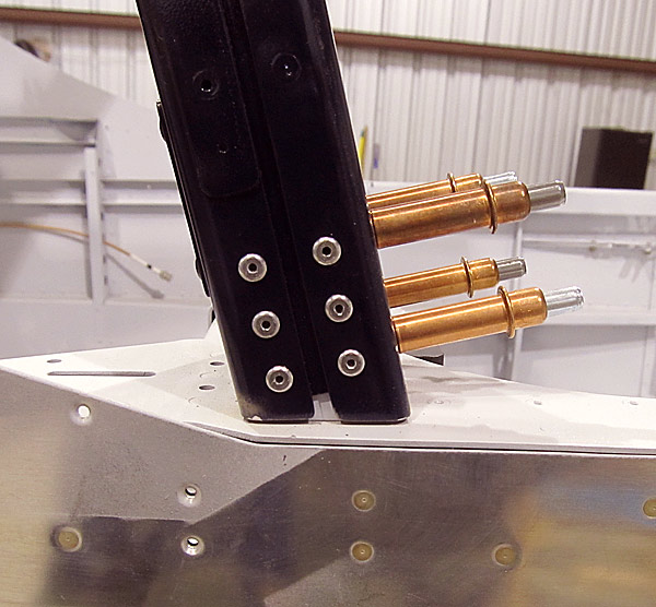 This is the right outboard side. |
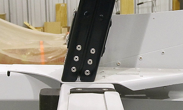 This is the right inboard side. |
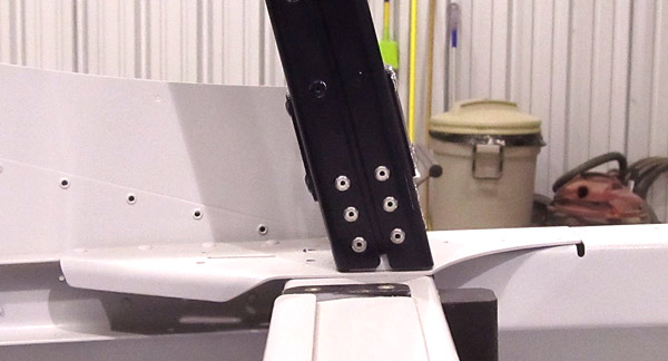 This is the left inboard side. |
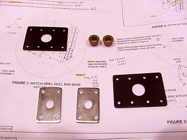 As per step seven, on page 37-06, referencing figure one, I riveted the (C-01432) bushing doublers to the roll bar assembly and the (F-01431D) roll bar base with LP4-3 and LP4-5 rivets as shown in figure two. |
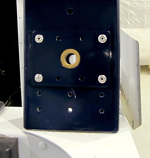 Here the four rivets are in place on the left side of the roll bar assembly. |
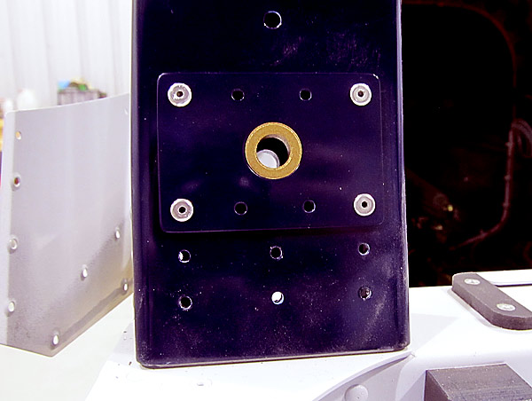 Same thing goes for the right side of the roll bar assembly... |
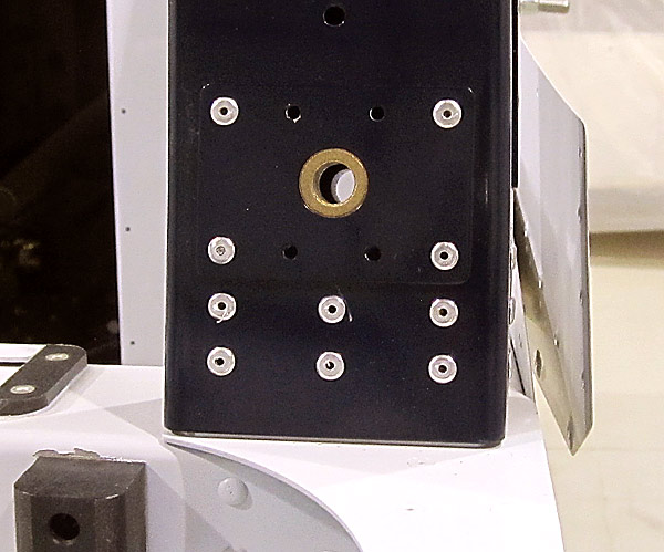 The remaining six holes in each side of the forward face of the roll bar assembly recieve LP4-3 rivets as shown in figure two. |
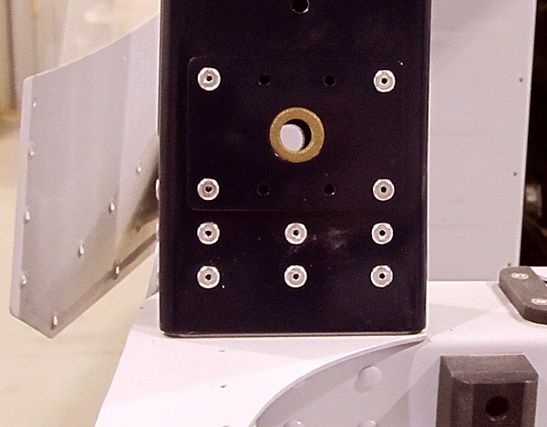 This is the right side of the roll bar assembly. |
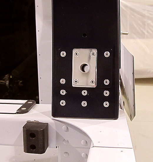 As per step eight, on page 37-06, referencing figure three, the (BUSHFBZ.502x.377x.375) flange bushings have been installed and in step nine, on page 37-06, the (C-01433) bushing covers have been installed with LP4-3 rivets on the top half and LP4-5 rivets set on the bottom half of the (C-01433) bushing covers. |
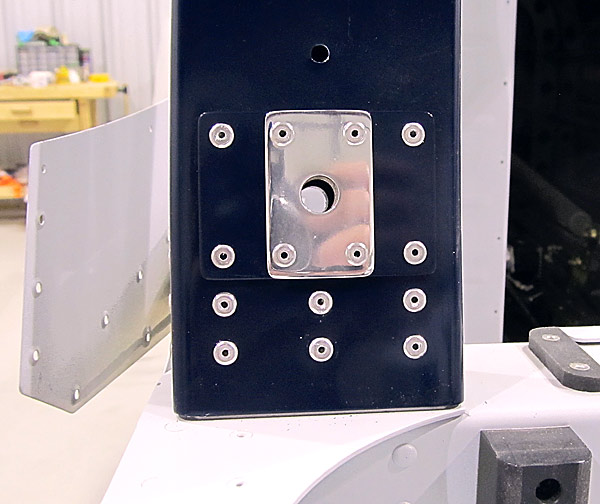 This is the right side of the roll bar assembly. |
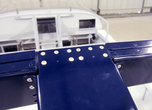 As per step one, on page 37-07, referencing figure one, the (F-01432A) roll bar brace was riveted to the roll bar assembly using CR3212-4-3 and CR3213-4-3 rivets as called out in figure one. |
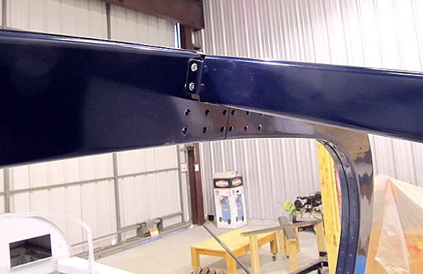 As per step one, on page 37-07, referencing figure one I riveted the sides of the (F-01432A) roll bar brace to the roll bar assembly using LP4-3 rivets as called out in figure one. |
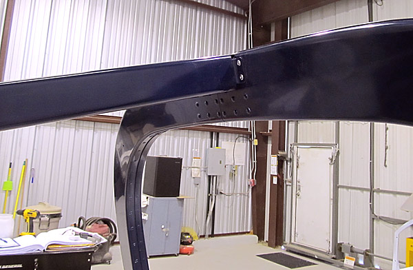 This is the right side of the roll bar brace. |
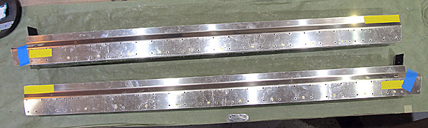 I marked the holes on the left and right canopy rail assemblies that do not get machine countersunk with yellow tape and marked the holes that are to be countersunk to fit the head of a AN426AD3 type rivet with blue tape. |
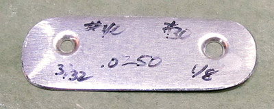 Some of the holes (majority of them) need to be machine countersunk to accept a #40 sized dimpled .025" skin so I made a gauge to check my countersink depth. |
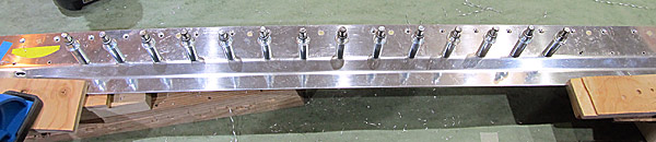 With the aid of a backer support bar to guide the pilot pin of the countersink bit to prevent "wandering" I began to machine countersink the open holes of the left and right canopy rail assemblies as per step one, on page 38-15, referencing figure one. |
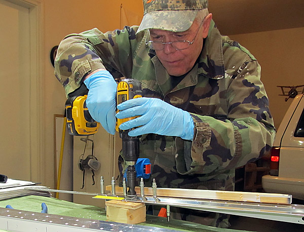 Let the machine countersinking begin! |
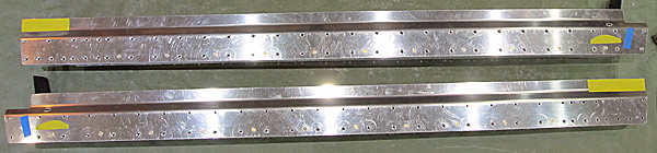 As per step one, on page 38-15, referencing figure one, machine countersunk the open holes in the left and right canopy rail assemblies as described in figure one. |
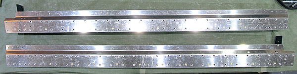 Remember those pieces of blue tape that mark the three holes that are machine countersunk to fit the head flush of a AN426AD3 type rivet? Those holes were machine countersunk as described in figure one, step one, on page 38-15. |
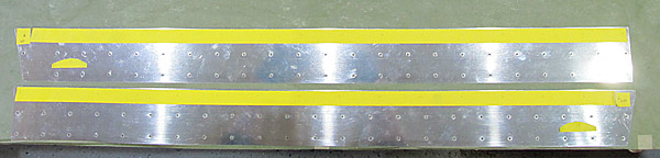 I marked the holes in the (C-01419-L and C-01419-R) left and right canopy side skins that DO NOT get dimpled with yellow tape. |
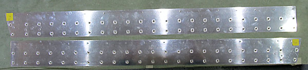 As per step two, on page 38-15, referencing figure two, the holes in the (C-01419-L and C-01419-R) left and right canopy side skins that were not marked with yellow tape were dimpled with 3/32" dimple dies using our DDR2 dimple machine. |
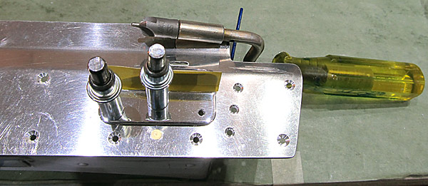 As per step three, on page 38-15, referencing figure three, the holes in the (C-01437-L and C-01437-R) left and right canopy handles were machine countersunk to fit the head of a AN426AD3 rivet. |
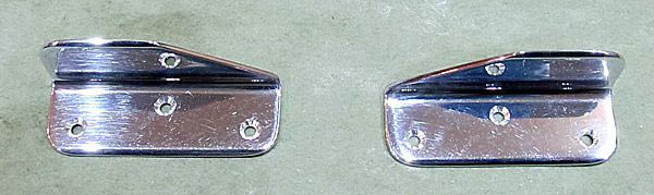 This is the finished countersink. |
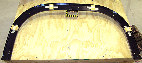 I am custom fitting the aft canopy frame assembly to the aircraft fuselage and the roll bar assembly. |
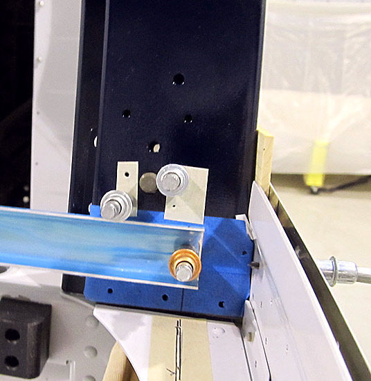 The next thing that I did was to cleco the (C-01419-L and C-01419-R) left and right canopy side skins to the left and right canopy rail assemblies. Then, I clamped these assemblies to the fuselage frame in the approximate position that they will be sitting in when completed. |
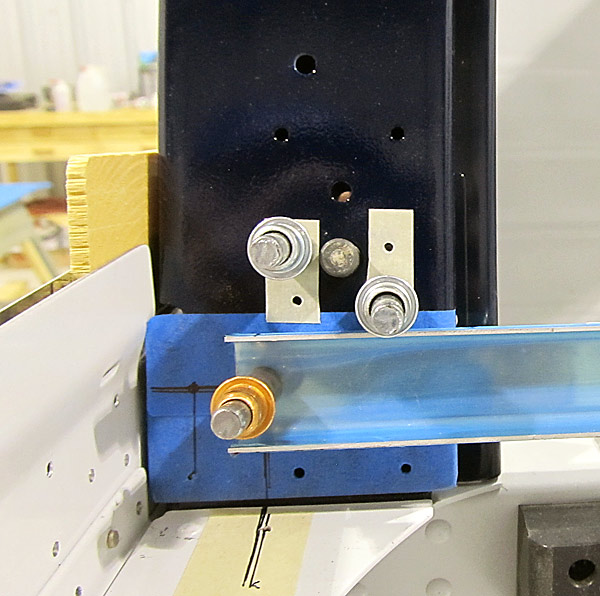 After everything was properly aligned, the (C-01442C) aft canopy fixture was clecoed to the (C-01405-L and C-01405-R) aft canopy frames as shown in figure three, on page 38-14. |
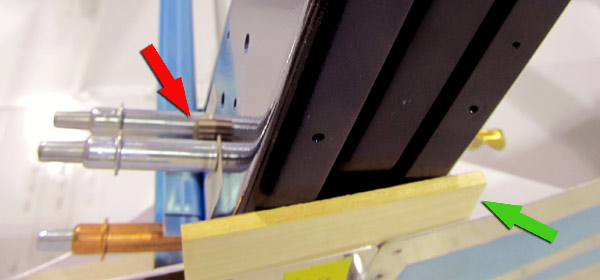 This photograph shows the side position setup better. The red arrow shows the 11/32" drill bit used to hold alignment through the canopy latch pin holes. The green arrow shows the 9/64" plexiglass thickness blocks used to ensure the glass will fit where its supposed to in width. At the bottom of the photograph you can faintly see the skin alignments....it is easier to see in the next picture. |
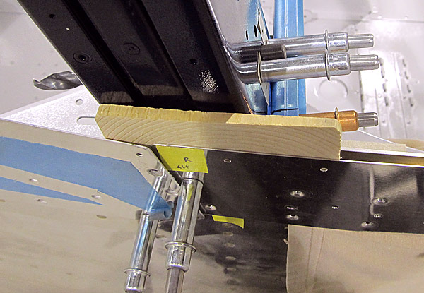 This is the right fuselage side of the position setup. It shows the position of the side skins better. |
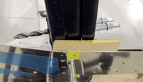 This photograph shows the 11/32" drill bit that is passing through the roll bar assembly and the aft canopy frame assembly, ensuring proper alignment where the canopy latch pins will be. |
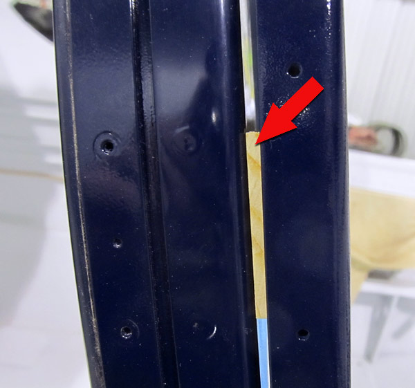 This is a slightly better photograph showing the (C-01441) spacer block that ensures the aft canopy frame sits the proper distance in front of the roll bar assembly. |
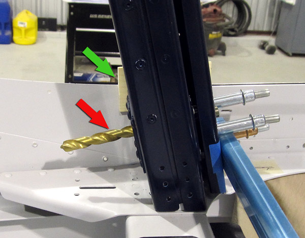 This photograph shows the left inboard side position setup. The red arrow shows the 11/32" drill bit used to hold alignment through the canopy latch pin holes. The green arrow shows the 9/64" plexiglass thickness blocks used to ensure the glass will fit where its supposed to in width. |
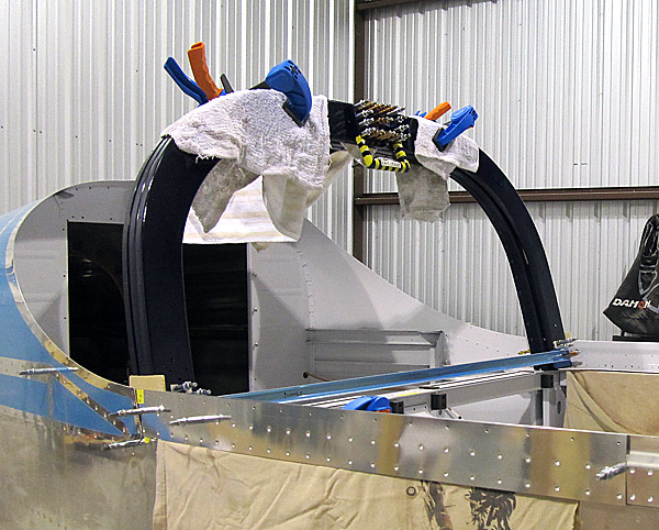 Finally, as per step five, on page 38-14, I final drilled #40 the .094" holes in the canopy handle assembly into the (C-01405-L and C-01405-R) left and right aft canopy frames, clecoing each hole as it was drilled. |
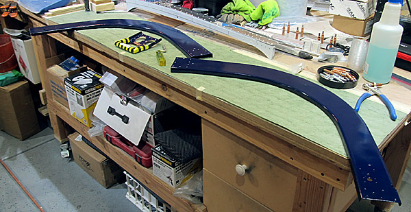 As per step seven, on page 38-14, the canopy handle assembly was removed from the aft canopy frames and all of the newly drilled holes were deburred. |
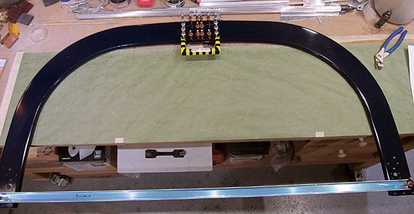 I sanded the (C-01405-L and C-01405-R) left and right canopy frames with up to 3000 grit sandpaper and buffed the paint with my Griot's Garage G8 3" Mini Random Orbital (#10908) polisher and polishing compounds to achieve a smooth glass like finish and re-clecoed all of the parts from step four, on page 38-14, referencing figure three, in preparation for riveting. |
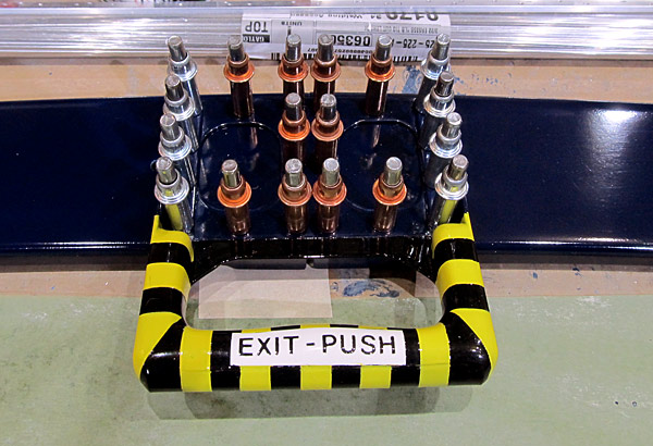 As per step eight, on page 38-14, referencing figure three, I am riveting the (C-01405-L and C-01405-R) left and right aft canopy frames and the canopy handle assembly together using rivets called out in figure three, starting in the center, setting AN470AD4-5 rivets with our pneumatic squeezer. |
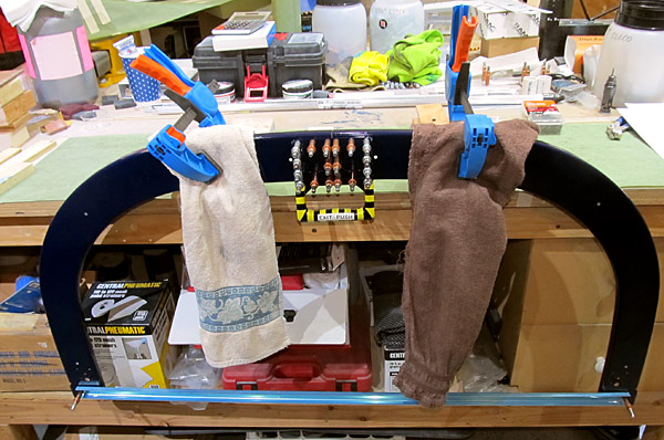 It was going to be easier to set these rivets if I positioned the frame assembly vertically on the work bench. |
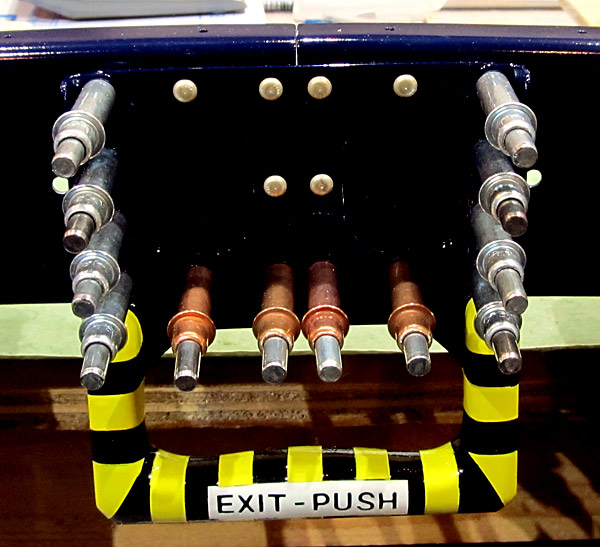 I could only reach so far using the pneumatic squeezer so I am going to set the side AN470AD3-6 rivets next, (because I can reach them okay with the pneumatic squeezer), but those four AN470AD4-5 rivets on the bottom row are going to have to be set with the rivet gun and a bucking bar because of the confined space they are in. |
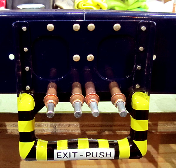 Here is what I was mentioning above, I positioned the manufactured "domed" part of the side rivets on the aft part of the aft frame assembly because the gap along the side portion of the canopy handle assembly is too narrow to get the top jaw of the pneumatic squeezer into place to set the rivet. |
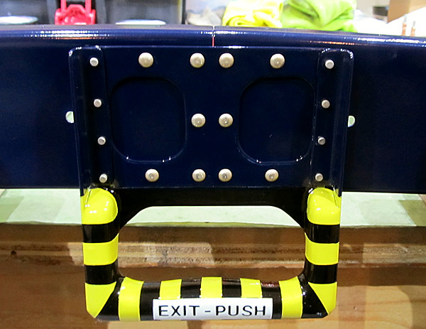 The rivets are set! |
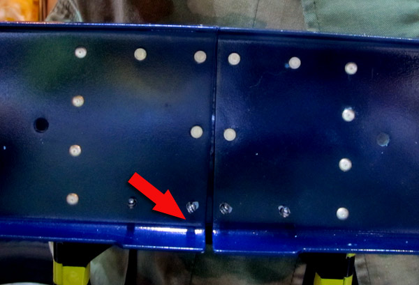 I don't know who made the (C-01405-L and C-01405R) aft canopy frames but they were misaligned to the point that Van's Aircraft tech support suggested that I fit everything in place on the fuselage, which I described earlier, but now you can see how much of a gap that was! |
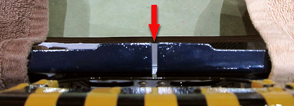 That's about a 1/8" gap! |
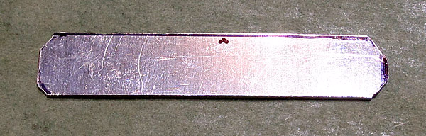 Because of the misalignment in the manufacture of the aft canopy frames a new (C-01405D) aft canopy frame splice has to be fabricated by me because the original factory part would not have sufficient edge distance for the rivets needed to complete the structure. |
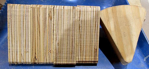 Since I had the bandsaw out to cut the new aft canopy frame splice, I thought I would go ahead and cut out cross sections from thick plywood in order to construct the custom sanding block as described on page 38-41, it is to be 6" long. |
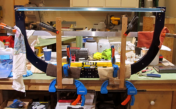 As per step nine, on page 38-14, referencing figure three, and to make the riveting go easier, I repositioned the aft canopy frame assembly so that the bottom surface was pointed upwards. Supports were added to make sure that the entire frame was properly aligned and that the forward surfaces of the frames were parallel. |
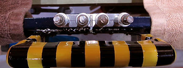 The edges of the newly fabricated (C-01405D) aft canopy frame splice were deburred and the gap that exists in the aft canopy frame was drawn on the splice as was the centerline. |
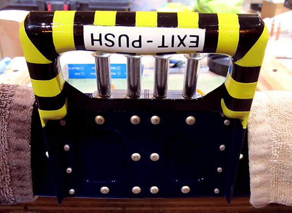 Here's another view... |
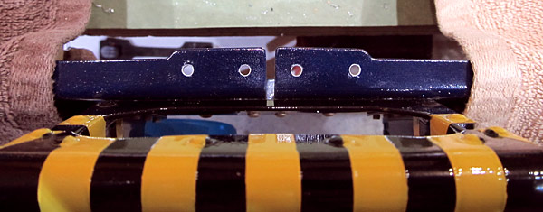 The #40 holes were final drilled to #30 and then the splice was removed and all of the holes were deburred as per step eleven, on page 38-14. |
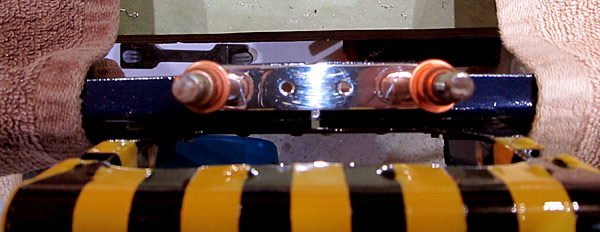 I polished the (C-01405D) aft canopy frame splice then reclecoed it into position. |
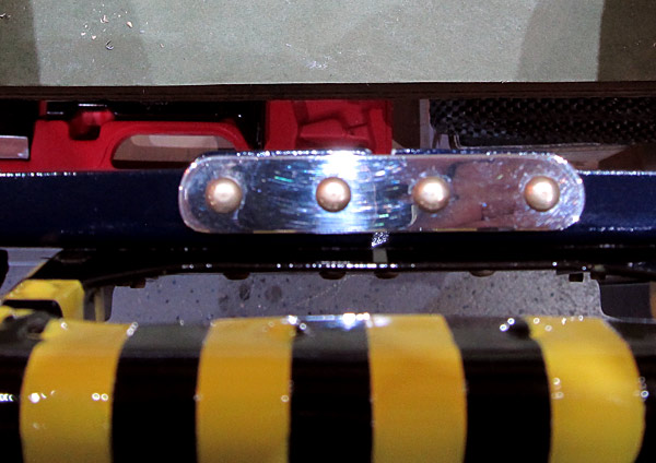 As per step twelve, on page 38-14, the (C-01405D) aft canopy frame splice was riveted to the aft canopy frame assembly with AN470AD4-5 rivets using our 3x rivet gun and a tungsten bucking bar. |
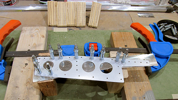 As per step four, on page 38-15, referencing figure four, I am machine countersinking every hole in the (C-01406-L) left forward canopy rail to accept a dimpled .025 skin flush to the outside. |
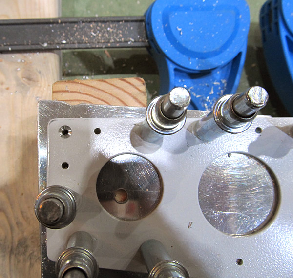 I know it takes a little longer to countersink this way but the results are much more satisfying... |
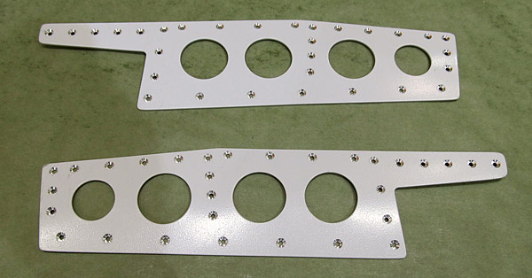 Both of the (C-01406-L and C-01406-R) left and right forward canopy rails have been machine countersunk. |
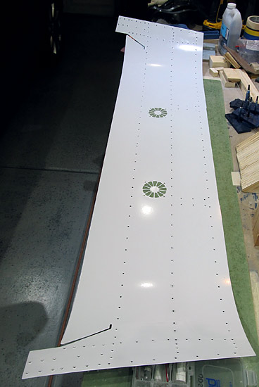 As per step five, on page 38-15, referencing figure five, I dimpled the remaining un dimpled holes in the (C-01418) canopy skin, except those indicated in figure five around the fan mounts. |
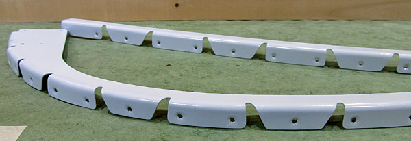 As per step seven, on page 38-15, referencing figure six, all of the holes in the flanges of the (C-01404-L and C-01404-R) left and right support flanges were dimpled except those as indicated in figure six. |
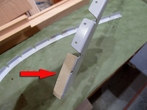 The last three holes on each of the (C-01404-L and C-01404-R) left and right support flanges do not get dimpled so I taped them off so I did not inadvertently dimple them. |
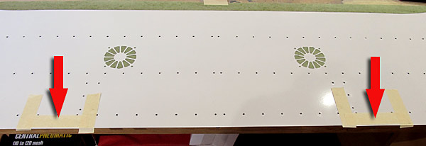 There are two sections on the (C-01418) canopy skin, around the hinges, that need to be beveled on the underneath forward side to ensure proper clearance when the canopy is closed so I taped off the three inch area as indicated in figure five. |
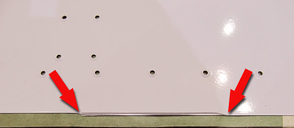 As per step six, on page 38-15, referencing figure five and the detail enlargement, I sanded a radius into the underside of the forward outside edges of the (C-01418) canopy skin about 3" long each. |
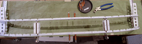 As per step one, on page 38-16, using the four outboard holes, the (C-01428) splice plates were clecoed to the (C-01402-L and C-01402-R) and (C-01403-L and C-01403-R) canopy frames. |
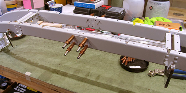 Here is a little better view... |
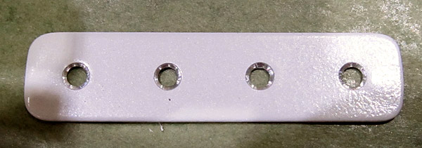 As per step four, on page 38-16, I machine countersunk the forward side of the (C-01404A) support flange splice flush to fit the head of a NAS1097AD3-3 rivet using a hand countersink tool equipped with a #40 piloted countersink bit. |
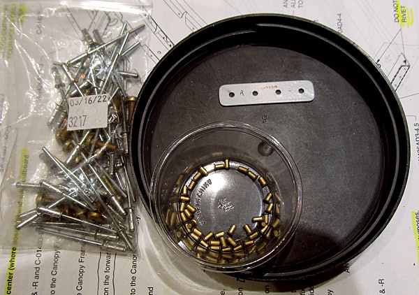 These are the NAS1097AD3-3 rivets that will be used to attach the (C-01404A) support flange splice to the (C-01404-L and C-01404-R) left and right support flanges. The rivet is 3/16" long and 3/32" in diameter. |
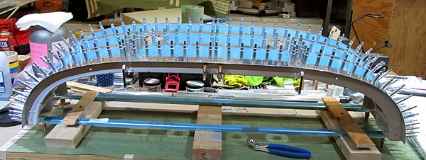 As per step two, on page 38-16, I clecoed the (C-01442A) forward canopy fixture and the (C-01442B) mid canopy fixture to the canopy frame assemblies per figure one, on page 38-09. |
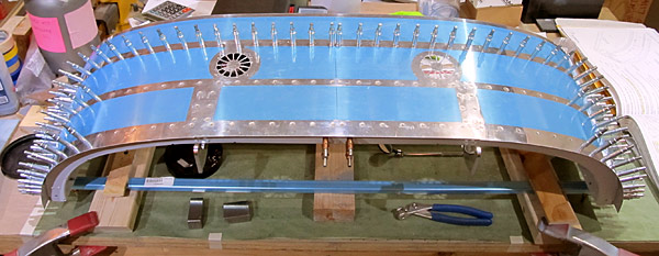 As per step six, on page 38-16, referencing figure one, I began the process of riveting the (C-01418) canopy skin to the (C-01402-L and C-01402-R) left and right forward canopy frames and the (C-01403-L and C-01403-R) left and right mid canopy frames, beginning in the middle and working symetrically outwards. |
 Riveting the canopy skin to the canopy assembly continues per step six, on page 38-16.... |
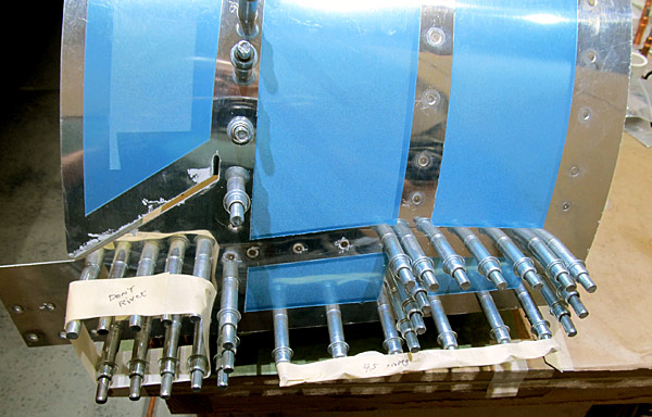 This is the right side (C-01406-R) forward canopy rail getting riveted to the (C-01418) canopy skin. |
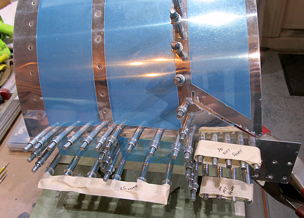 This is the left side (C-01406-L) forward canopy rail getting riveted to the (C-01418) canopy skin. |
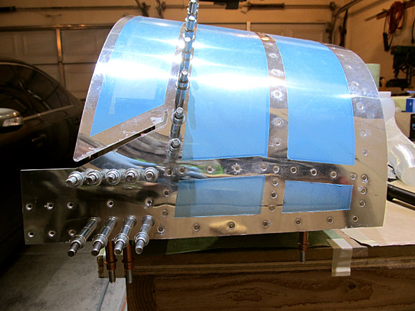 As per step eight, on page 38-16, referencing figure one, this is the right side (C-01406-R) forward canopy rail riveted to the (C-01418) canopy skin and understructure. |
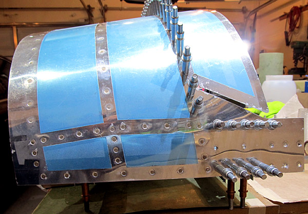 As per step eight, on page 38-16, referencing figure one, this is the left side (C-01406-L) forward canopy rail riveted to the (C-01418) canopy skin and understructure. |
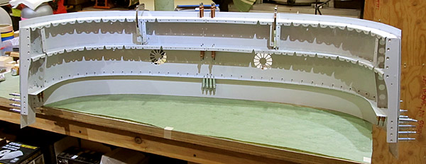 As per step nine, on page 38-16, I removed the (C-01442A) forward canopy fixture and the (C-01442B) mid canopy fixture from the canopy assembly. |
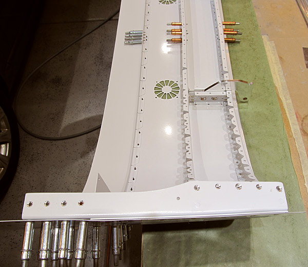 As per step ten, on page 38-16, but referencing figure two on page 38-17, the (C-01408-L and C-01408-R) left and right forward canopy rail bases have been machine countersunk to fit a .025 dimpled skin and the heads of AN426AD4 rivets where indicated. |
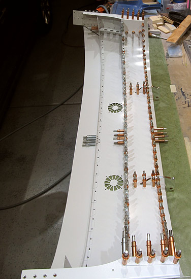 As per step eleven, on page 38-16, referencing page 38-09 and figure one, I clecoed the (C-01417) canopy close out to the canopy assembly, making sure to cleco every hole. |
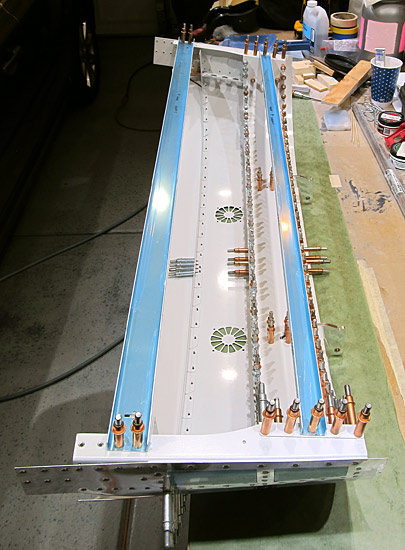 As per steps twelve and thirteen, on page 38-16, I re-attached the (C-01442A) forward canopy fixture and the (C-01442B) mid canopy fixture to the canopy assembly. |
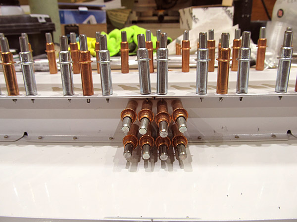 As per step fourteen, on page 38-16, referencing figure one, I am final #30 drilling the holes common to the (C-01428) canopy frame splices and the (C-01403-L and C-01403-R) left and right mid canopy frames clecoing each hole as drilling progresses. |
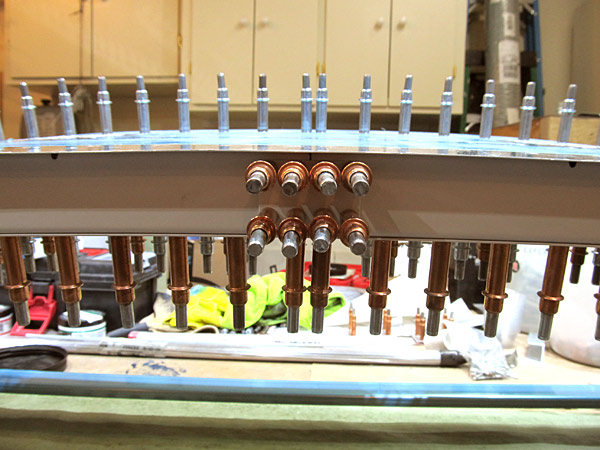 As per step fourteen, on page 38-16, referencing figure one, I am final #30 drilling the holes common to the (C-01428) canopy frame splices and the (C-01402-L and C-01402-R) left and right forward canopy frames clecoing each hole as drilling progresses. |
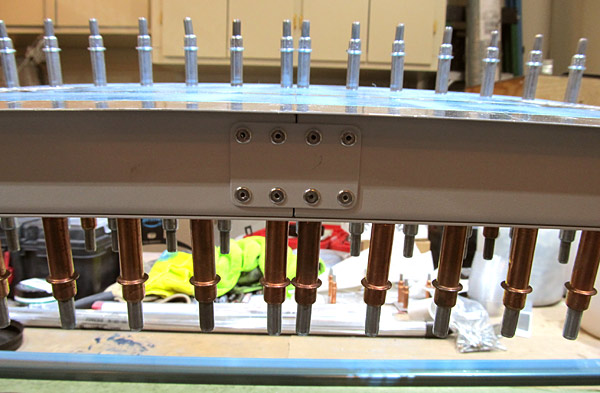 As per step fifteen, on page 38-16, referencing figure one, I riveted the (C-01428) canopy frame splice to the (C-01402-L and C-01402-R) left and right forward canopy frames, removing one cleco at a time, while setting LP4-3 rivets using the hand rivet gun. |
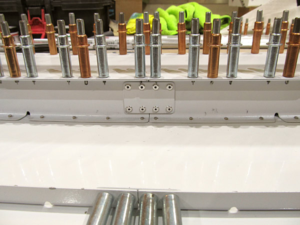 As per step fifteen, on page 38-16, referencing figure one, I riveted the (C-01428) canopy frame splice to the (C-01403-L and C-01403-R) left and right mid canopy frames, removing one cleco at a time, while setting LP4-3 rivets using the hand rivet gun. |
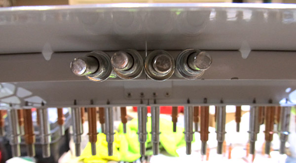 As per step seventeen, on page 38-16, referencing figure one, I am riveting the (C-01404A) support flange splice to the (C-01404-L and C-01404-R) left and right support flanges setting NAS1097AD3-3 rivets with our hand squeezer. |
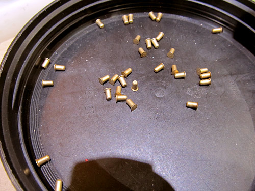 These are the NAS1097AD3-3 rivets used to rivet the (C-01404A) support flange splice to the support flanges. the rivets are 3/16" long and 3/32" in diameter. |
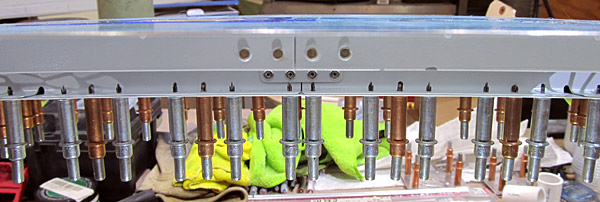 here is the (C-01404A) support flange splice riveted in place. |
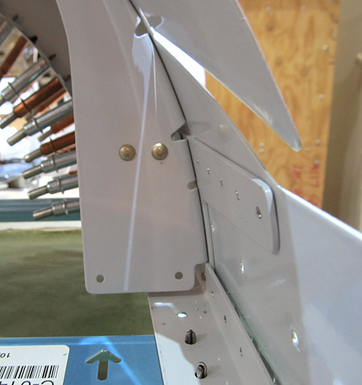 As per step eighteeen, on page 38-16, referencing figure one, I riveted the (C-01404-R) right support flange to the aft flange of the (C-01416-R) right intercostal using our pneumatic squeezer setting AN470AD4-4 rivets. |
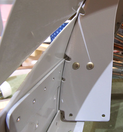 As per step eighteeen, on page 38-16, referencing figure one, I riveted the (C-01404-L) left support flange to the aft flange of the (C-01416-L) left intercostal using our pneumatic squeezer setting AN470AD4-4 rivets. |
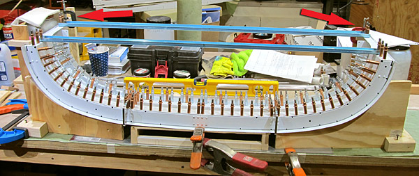 Step one, on page 38-17, calls for checking of twist in the canopy assembly, (Van's unofficial maxium twist is 0.2°), and in measuring mine, (as careful as I have been), I find that my canopy assembly has a very slight twist in it. |
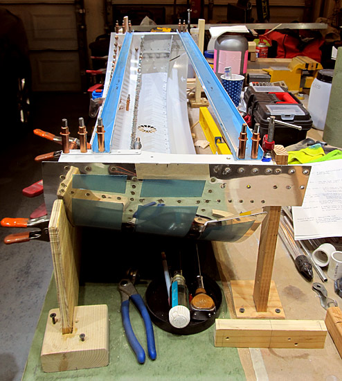 This is what the jig looks like from the side. |
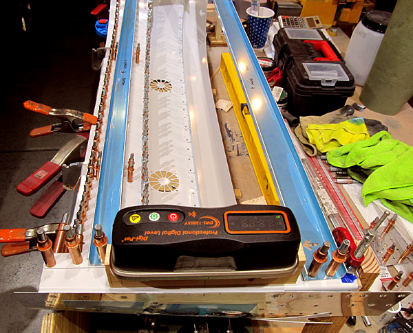 I am using a Digi-Pas® DWL-1300XY digital level to measure my "twist" angles with. |
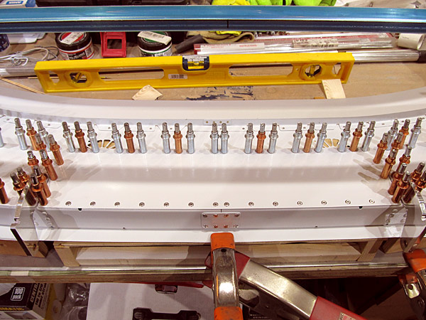 As per step two, on page 38-17, referencing figure one, I am final #30 drilling the row of 1/8" holes indicated by "step 2" and clecoing each hole as drilling progresses, checking for twist every fourth rivet hole. |
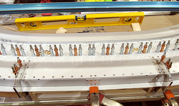 As per step four, on page 38-17, referencing figure one, I final #30 drill the 1/8" holes common to the (C-01415-L and C-01415-R) forward intercostals, the left and right canopy hinge assemblies, and the (C-01402-L and C-01402-R) forward canopy frames making sure not to drill those holes indicated by circles and "step 4" in the call outs, clecoing each hole as drilling progressed. |
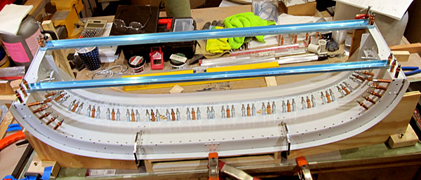 As per step five, on page 38-17, referencing figure one, I riveted all but sixteen holes, (next session will get these), all #30 holes drilled in step four and indicated by "step 5" with LP4-3 rivets. |
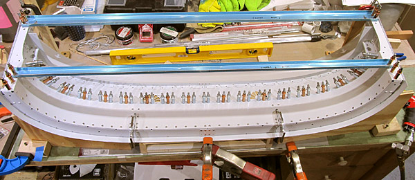 Finished steps four and five, on page 38-17, referencing figure one, checking for twist every fourth rivet set, and all circled holes, (copper clecos), were not drilled. |
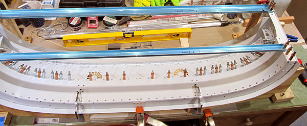 As per step six, on page 38-17, referencing figure one, I final #40 drilled all the 3/32" holes along the aft edge of the (C-01417) canopy frame close out, as indicated by the "step 6" call out in figure one. |
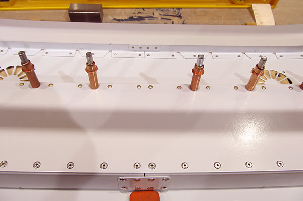 As the final #40 drilling progressed in step six, as per step seven, I riveted the hole with AN470AD3-4 rivets working from the center and symmetrically working outward using our 3x rivet gun and a tungsten bucking bar, checking for twist every fourth rivet set. |
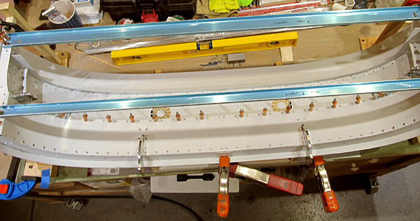 Almost done, fourteen more to go...the copper clecos do not get riveted. |
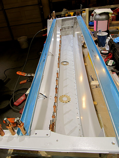 As per steps six and seven, on page 38-17, referencing figure one, I continued to final #40 drill and rivet the 3/32" holes along the aft edge of the (C-01417) canopy frame close out, setting AN470AD3-4 rivets using the 3x rivet gun and tungsten bucking bar, checking for twist after every fourth rivet was set. |
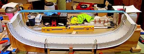 As per step eight, on page 38-17, referencing figure one, I riveted the flanges on the (C-01417) canopy frame close out with CS4-4 rivets as indicated by "step 8" call out in figure one. |
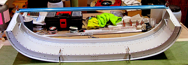 As per step nine, on page 38-17, referencing figure one, the (C-01442A) forward canopy fixture was removed and the whole assembly was taken out of my homemade jig. |
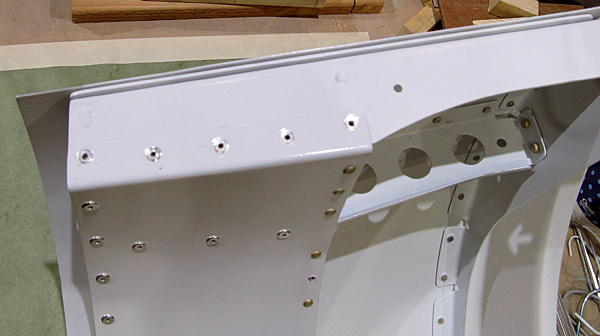 As per step ten, on paghe 38-18, referencing figure one, I riveted the remaining two holes in the canopy frame close out with CS4-4 rivets as indicated by the figure one "step 10" call out. |
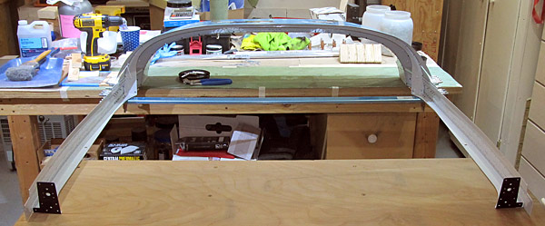 As per step one, on page 38-18, referencing figure one, detail A, the left and right canopy rail assemblies and the (C-01411) canopy rail shims were clecoed to the canopy assembly. |
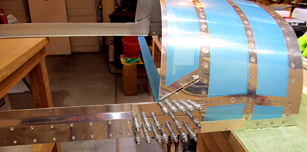 This is the right side of the canopy assembly with the canopy rail assembly attached. |
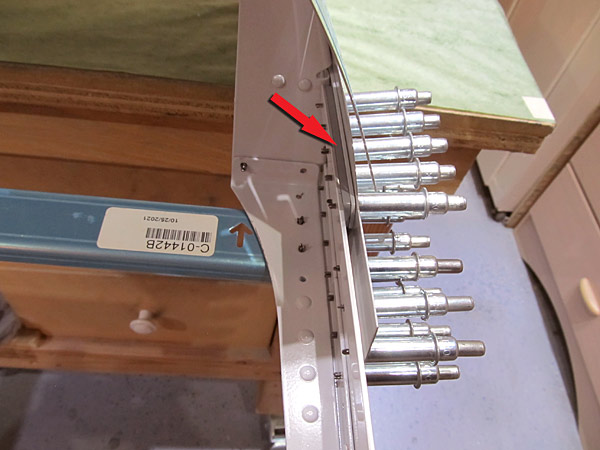 The arrow is pointing at the (C-01411) canopy rail shim. |
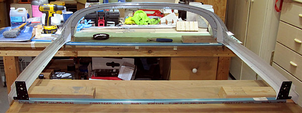 The (C-01442C) aft canopy fixture was clecoed into place and the aft canopy frame was left off for now. |
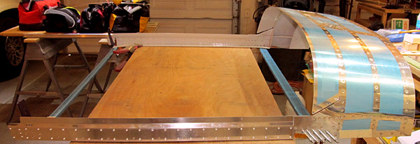 As per step two, on page 38-18, I am riveting the left and right canopy assemblies and the (C-01411) canopy rail shims to the canopy assembly with AN426AD3-7 rivets, most of which were set with the pneumatic squeezer, some of the hard to get at rivets had to be set with the 3x rivet gun and a tungsten bucking bar. The top row of rivets were set first. |
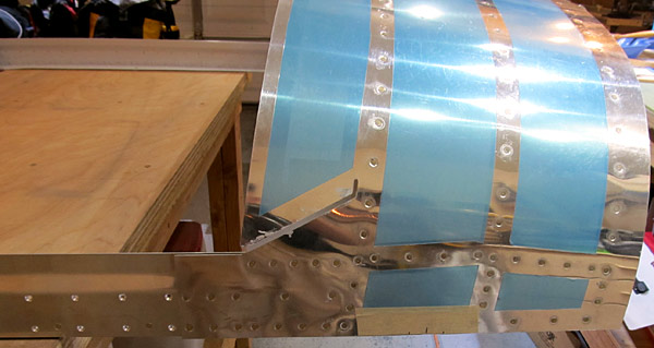 As per step two, on page 38-18, referencing figure one and the middle detail, I finished setting the AN426AD3-5 rivets on the bottom-side row of the canopy rail assembly to the canopy assembly. |
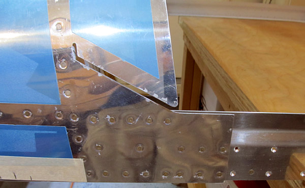 This is the left side of the canopy. |
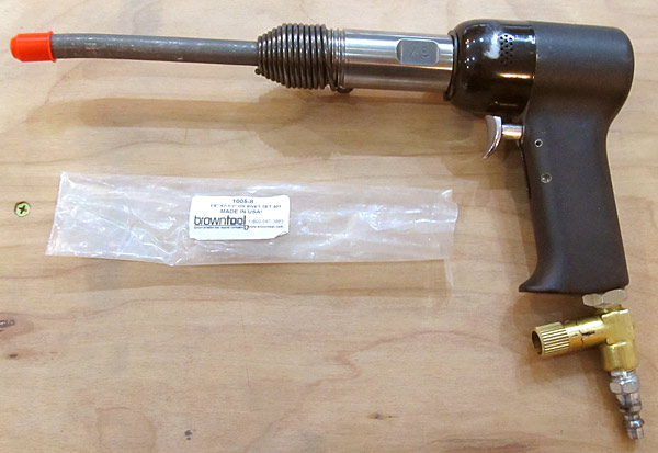 I had to use a 1/8" x 7 1/2" cupped, offset rivet set on the rivet gun in order to set the inner AN470AD4-4 rivets where the rail assemblies were joined to the canopy support flanges. It was very tight maneuvering.... |
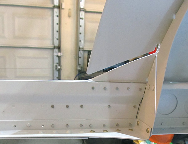 This is the inside view of the rivets that were used to join the canopy rail assemblies to the canopy assembly. |
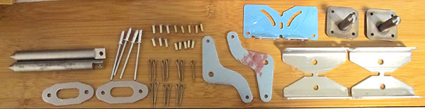 On a separate note, this is the contents of SB-00128 kit, which was issued to address the need to lengthen the locking pins for the canopy. They are: |
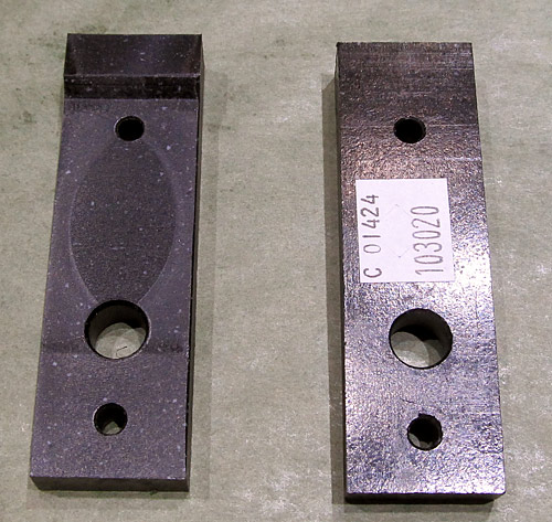 As per step one, on page 38-19, referencing figure one, the (C-01424) canopy pin blocks are to be machine countersunk to accept the head of a AN509-10R14 screw. |
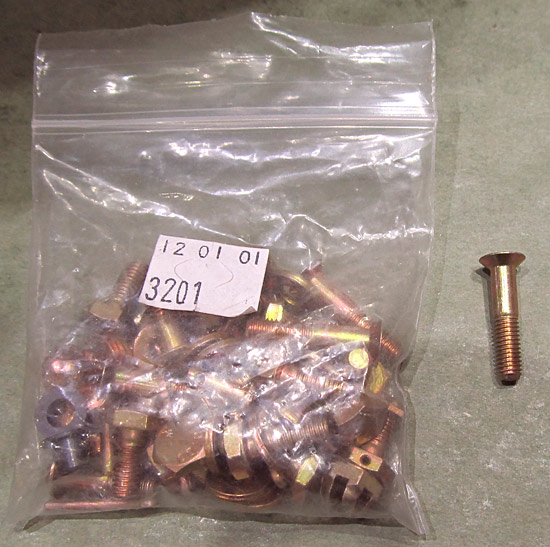 This is the AN509-10R14 screw. |
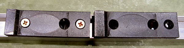 As per step one, on page 38-19, referencing figure one, the (C-01424) canopy pin blocks were machine countersunk to accept the head of a AN509-10R14 screw. |
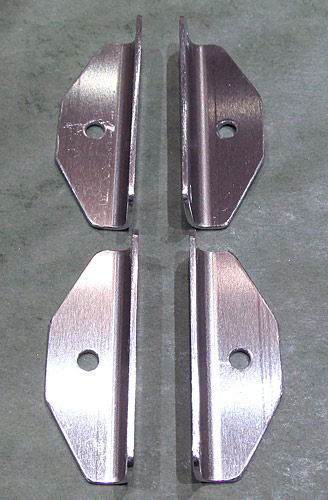 Service Bulletin 00128 was just issued and it deals with the latch and guide pins of the canopy being to short under aggressive aerobatic maneuvers; I am beginning to prepare the replacement parts in the SB-00128 kit in order to comply with the service bulletin. |
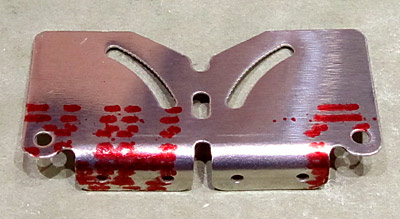 These are the (C-01459-L and C-01459-R) left and right switch brackets. They need to be separated. |
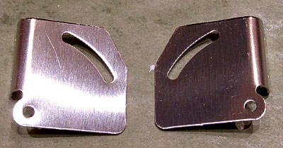 I separated the (C-01459-L and C-01459-R) left and right switch brackets, the edges and holes will be deburred next. |
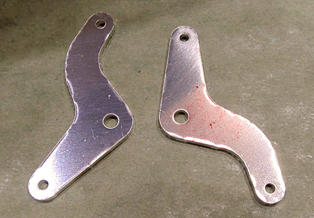 These are the (C-01455) latch bellcranks. They will have their edge and holes deburred. |
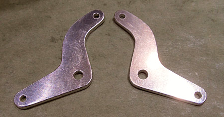 The two (C-01455) latch bellcranks have had the edges and holes deburred. |
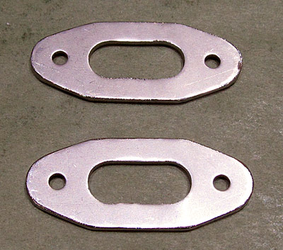 These are the new (C-01457) guide plates, they are very tough and the edges need some serious deburring. |
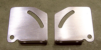 The (C-01459-L and C-01459-R) left and right switch brackets have had their edges and all holes have been deburred, in addition, the surfaces have been scuffed with maroon and gray Scotch-Brite™ pads in preparation for priming. |
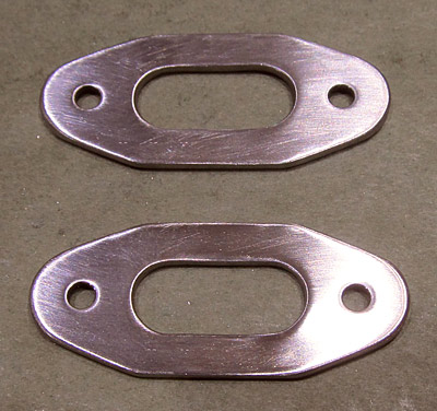 The two (C-01457) guide plates have had their edges deburred and the holes deburred, in addition the surfaces have been sanded in preparation for priming. |
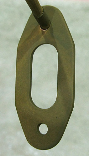 The two (C-01457) guide plates were cleaned with Southern Polyurethanes Incorporated (SPI) 700-1 wax and grease remover and after they dried were primed with Tempo A-702 Valspar green primer. |
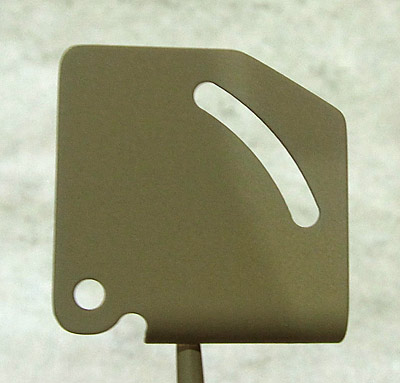 The two (C-01459-L and C-01459-R) left and right switch brackets were cleaned with Southern Polyurethanes Incorporated (SPI) 700-1 wax and grease remover and after they dried were primed with Tempo A-702 Valspar green primer. |
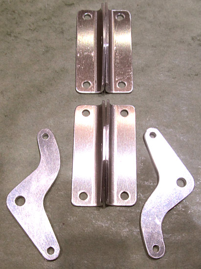 I intend to polish the (C-01460) bellcrank angles and the (C-01455) latch bellcranks so I began to lightly sand them with various grits of sandpaper in preparation for final polishing. |
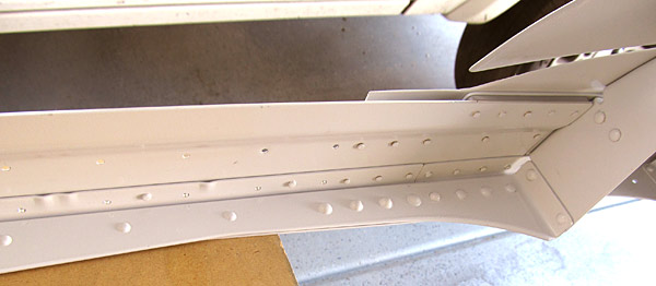 I primed and then topcoat painted the newly installed rivets on the left canopy rail assembly with Stewart Systems E5301 EkoCrylic smoke gray paint. |
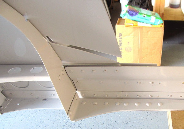 I primed and then topcoat painted the newly installed rivets on the right canopy rail assembly with Stewart Systems E5301 EkoCrylic smoke gray paint. |
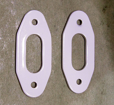 I topcoat painted the The two (C-01457) guide plates with Stewart Systems E5301 EkoCrylic smoke gray paint. |
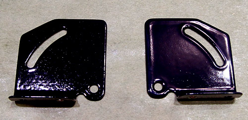 The two (C-01459-L and C-01459-R) left and right switch brackets were topcoat painted with Stewart Systems E5465 EkoCrylic royal blue paint. |
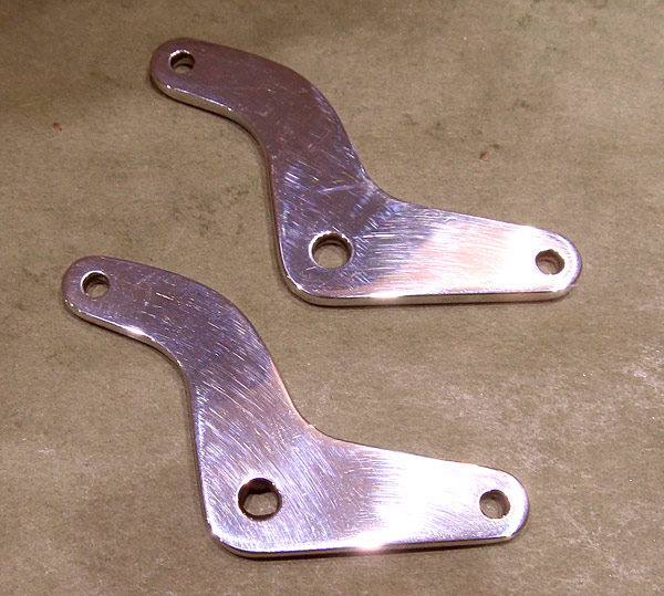 I am preparing the (C-01455) latch bellcranks for polishing by sanding them with various grits of sandpaper (up to 5000 grit). |
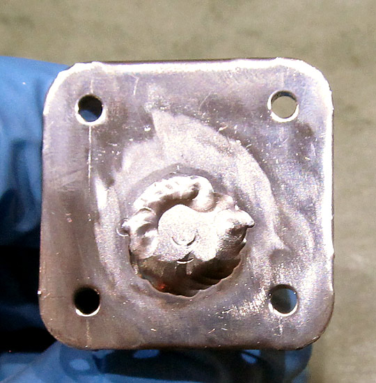 This is the (C-01458) guide pin, it is the Service Bulletin SB-00128 replacement for the original (C-01453) guide pins. |
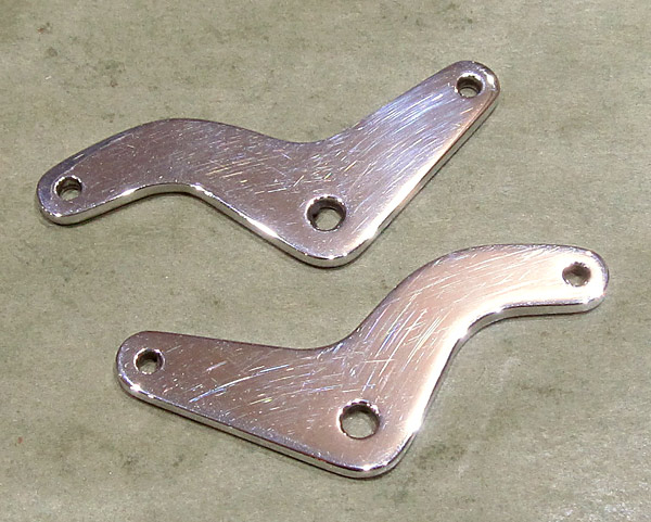 I am starting the metal polish process for the (C-01455) latch bellcranks using Nuvite®NuShine® IIA repolish and touch up compound. |
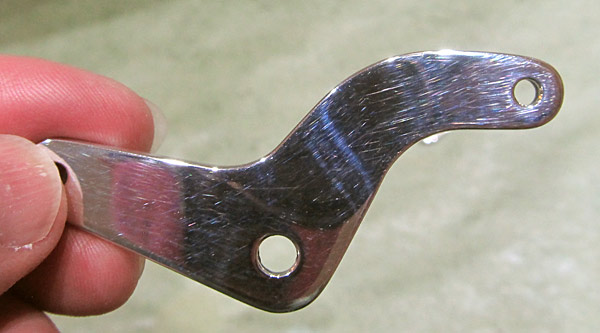 I finished step one in the polishing process of the (C-01455) latch bellcranks with the Nuvite®NuShine® IIA compound and now am moving into the finish polish stage using Nuvite®NuShine® IIS mirror finish... |
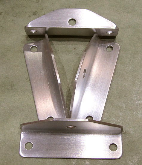 These are the four (C-01460) latch bellcrank angles. They replace the original (C-01429) latch bellcrank angles under the Service Bulletin SB-00128. |
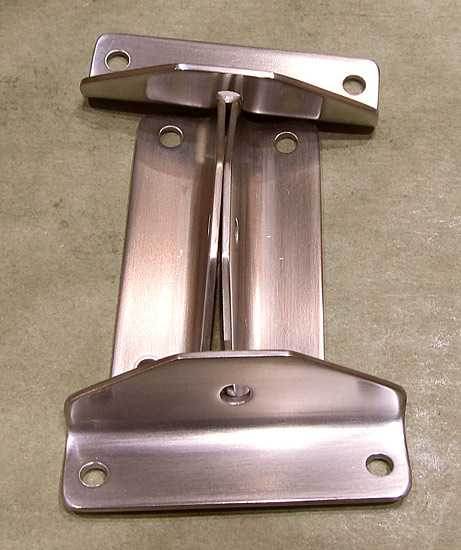 After further sanding with ultra fine sandpapers (up to 5000 grit) the four (C-01460) latch bellcrank angles are ready to be polished... |
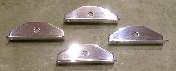 I am starting the metal polish process for the (C-01460) latch bellcrank angles using Nuvite®NuShine® IIA repolish and touch up compound. |
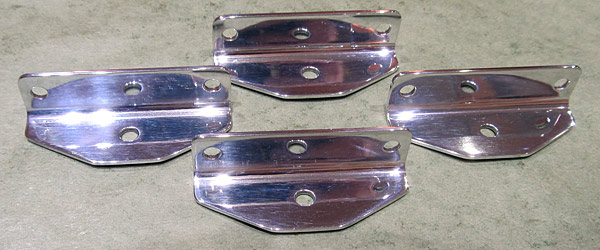 I finished step one in the polishing process of the (C-01460) latch bellcrank angles with the Nuvite®NuShine® IIA compound and now am moving into the finish polish stage using Nuvite®NuShine® IIS mirror finish... |
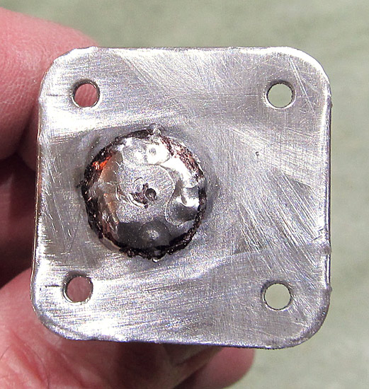 The (C-01458) guide pins are being sanded and deburred in preparation for polishing. |
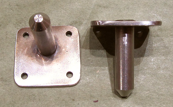 It's been tough going but the edges of the (C-01458) guide pins are deburred, as well as the holes. |
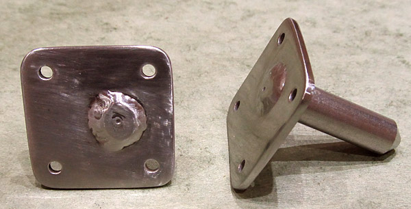 At this point the surfaces of the (C-01458) guide pins have been sanded with up to 1000 grit sandpaper but it's going to take a lot more sanding than that, if I want to get a mirror finish, so I continued to "step up" in the ultra fine grits to eventually 8000 grit. |
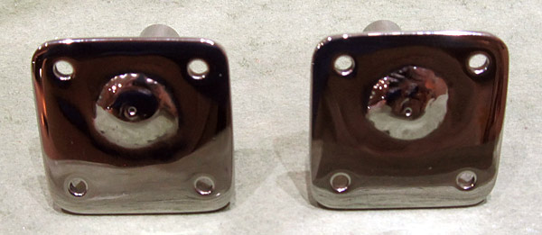 I polished the (C-01458) guide pins with Nuvite®NuShine® IIA and Nuvite®NuShine® IIS finish polish. |
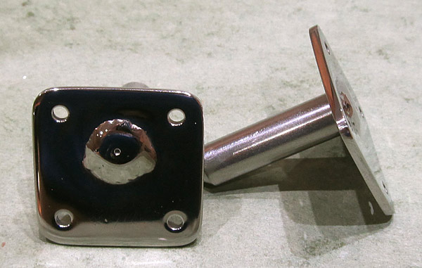 As you can see here, the center pin is longer on these replacement guide pins. |
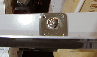 This photograph shows where the (C-01458) guide pins will sit on the (C-01427-L and C-01427-R) left and right aft canopy rail flanges, (as per figure one on page 38-37), ....not too pretty! |
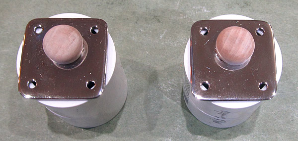 I think I have a solution to cover the (C-01458) guide pin center welds to make them look a little better. |
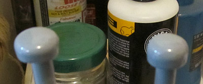 I primed the guide pin weld cover caps with Southern Polyurethanes Incorporated (SPI) 6610-4 gray epoxy primer. |
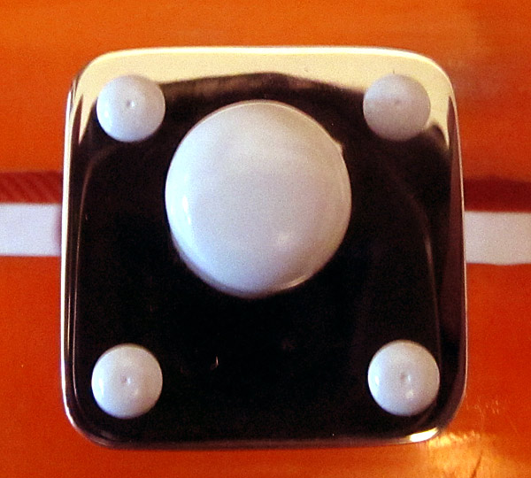 I top coated the guide pin weld cover caps with Stewart Systems E5301 EkoCrylic smoke gray paint. The rivets will be painted the same color, I think this will look much better than the ugly (but highly polished) center weld. |
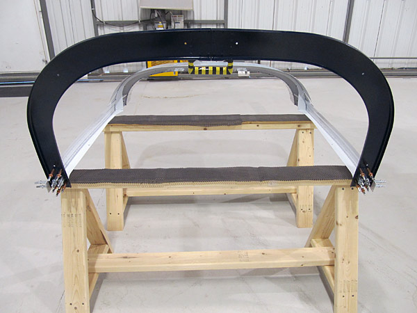 As per step three, on page 38-18, and referencing figure one and detail A, the aft canopy frame was clecoed to the canopy assembly in preparation for riveting. |
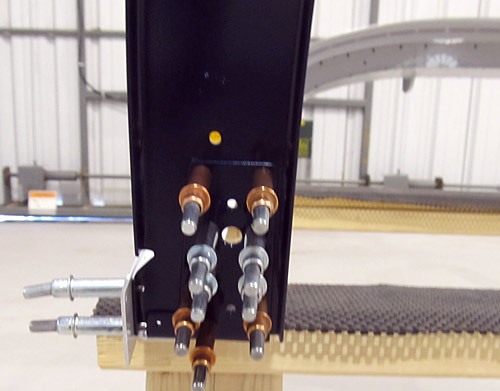 The left canopy frame assembly has some areas that are not to be riveted yet, the four silver #40 3/32" clecos in this photograph show which four holes they are, they will eventually be used to attach the (C-01459-L and C-01459-R) left and right switch brackets. |
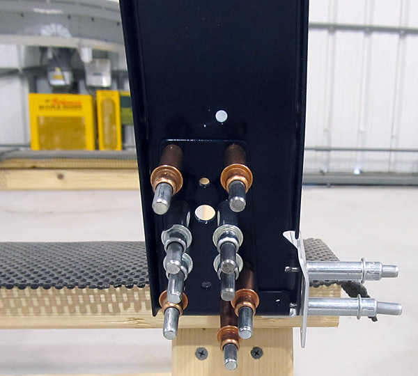 The right canopy frame assembly doesn't have any holes that shouldn't be riveted at this time, there are no switch brackets installed on this side. |
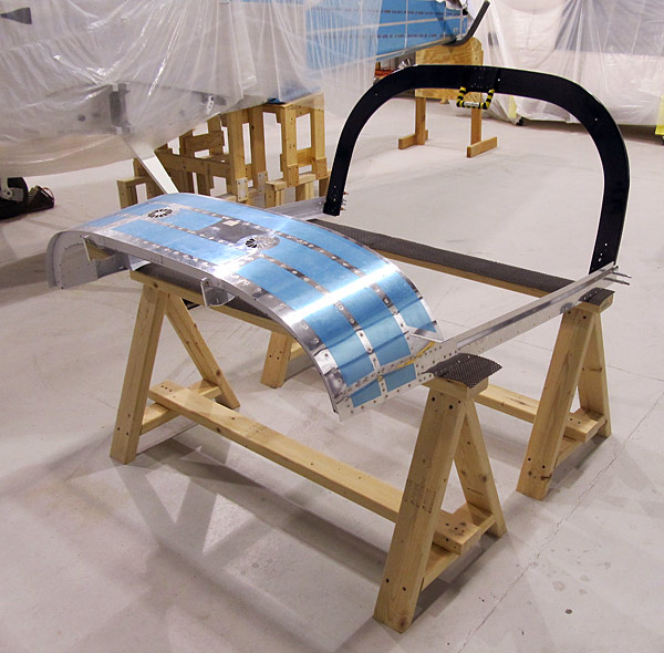 Here is what it looks like from the front... |
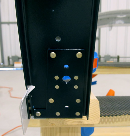 As per step three, on page 38-18, referencing figure one, and detail A, the aft canopy frame is being riveted to the canopy assembly. I started on the left side first. |
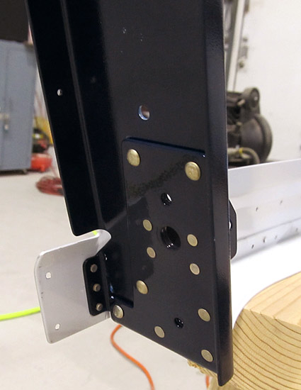 Also don't forget to set the rivets on the sides, they are AN426AD3-4.5 rivets. |
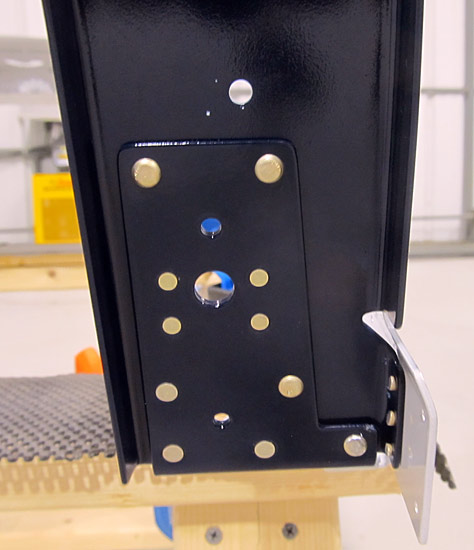 The right side attachment of the aft canopy frame to the canopy frame assembly was a little easier but I did make some rivet substitutions; when setting the center four rivets around the canopy pin hole area I used AN426AD3-4.5 rivets instead of the called out AN426AD3-4 rivets. |
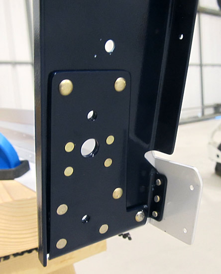 Just like in the left side, I set the bottom rivet on the side (C-01407-R) right aft canopy rail before I set the bottom AN470AD4-5 rivet on the aft canopy frame because it was easier to get to it with a bucking bar without that rivet head in the way. |
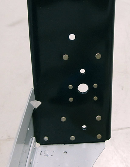 Here is what the right side looks like from the front. |
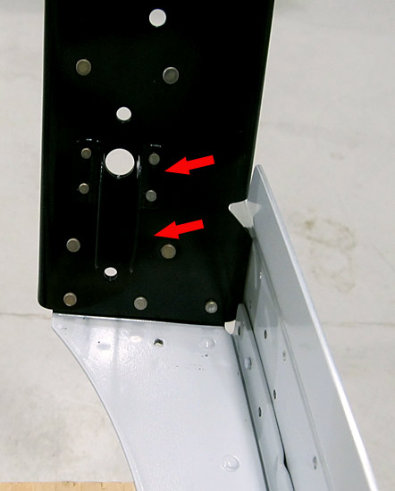 As per step five, in the Service Bulletin SB-00128 and step three, on page 38-19, referencing figure three, the (C-01459-L and C-01459-R) left and right switch brackets, replacements of the original (C-01445-L and C-01445-R) switch brackets, were riveted to the canopy frame using AN426AD3-5 rivets, (substituted for called out) AN426AD3-4 rivets, using our hand squeezer. |
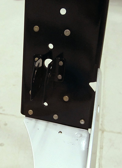 Here is a little better angle to see the (C-01459-L and C-01459-R) left and right switch brackets attached to the aft canopy frame. |
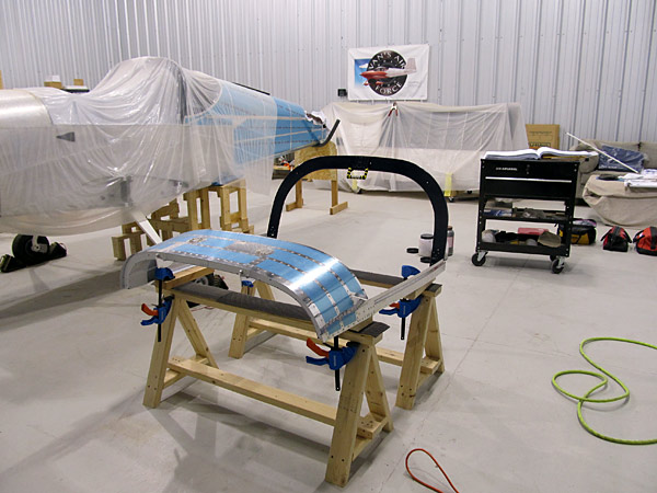 The aft canopy frame is now attached to the canopy assembly! |
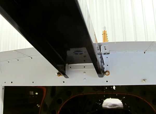 I will be attaching the roll bar braces flanges to the (F-01406C) bulkhead soon and I want to measure the individual holes grip lengths in case I am unable to set solid rivets. I want to know what sort of CherryMax® rivet I would need to do the job. |
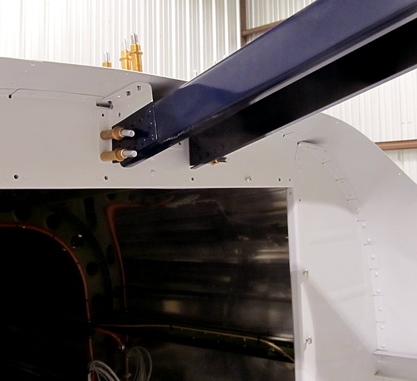 These three holes on the right side flange of the (F-01432B-R) right roll bar brace bracket would need a CR3213-4-3 CherryMax® rivet. |
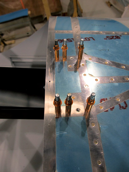 These eight holes on the (F-01475) aft fuselage top skin and (F-01475A) skin doubler are fairly easy to access and they will receive AN426AD4-5 rivets. |
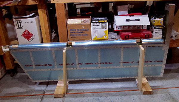 As per Service Bulletin SB-00043 steps one and two on page three, referencing figure three, I inspected all the rivets where the (E-1007 and E-00907) rear spars attach with the elevator skins on the top and bottom and found no cracks, therefore I proceeded to step five. |
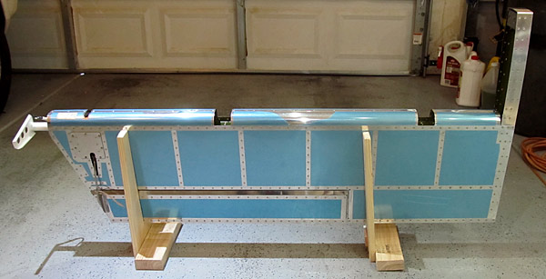 The purpose of this service bulletin is to take corrective action because according to Van's Aircraft "data from the field shows that the elevator skins on the RV10 and RV14/14A aircraft can crack around the rivets where the (E-1000 and E-00907) rear spar is attached". |
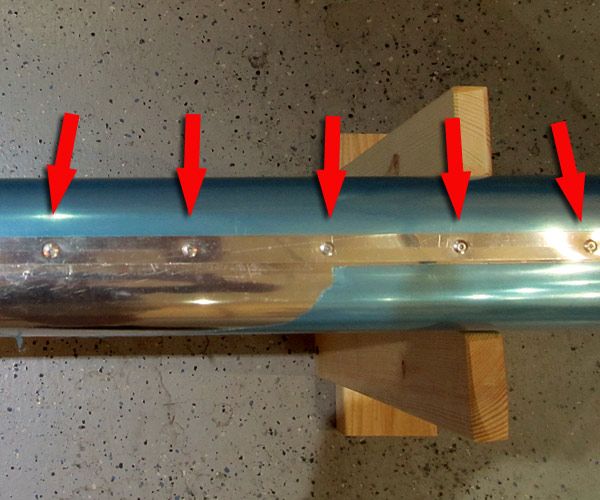 To permantly correct the situation from occuring in the future and to prevent having to inspect for cracks prior to every flight and every twelve month interval the next steps were taken: |
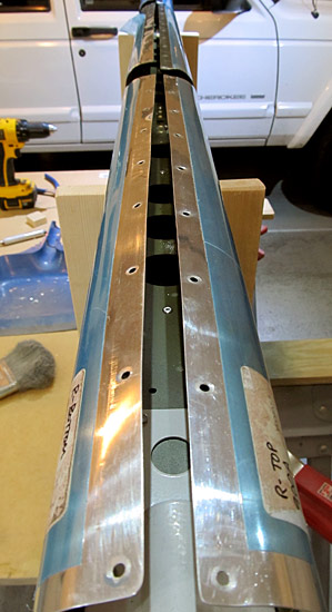 This is the right elevator and you can see that all of the rivets have been removed. |
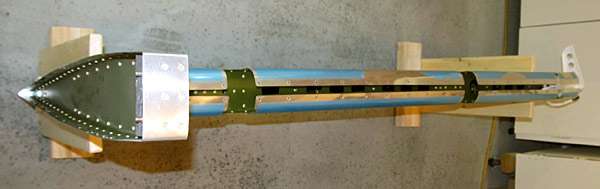 This is the left elevator and all of the rivets have been removed from the leading edge of it too. |
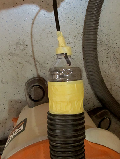 As per step seven, on page five of SB-00043 small 1.5" x 1.5" x 3" wood blocks were cut and used to keep the leading edge skins held apart so that the drill shavings and rivet tails could be vacuumed out of the internal cavities of the elevator as per step eight of SB-00043.. |
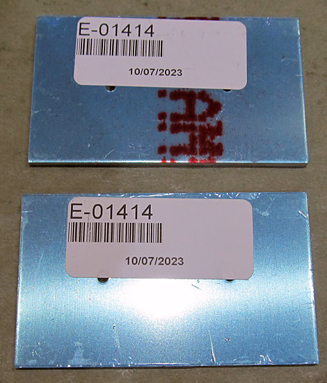 Time to debur the (E-01414) counterweights. |
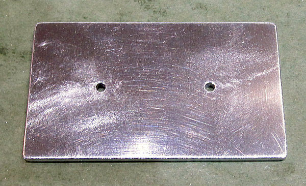 The holes and the edges of the (E-01414) counterweights were deburred. |
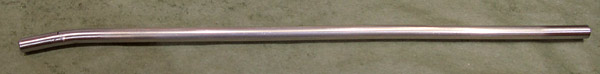 As per step nine, on page five of SB-00043, I cut the 3/8" aluminum tube to a length of 15" then deburred and radiused the edge of the tube so that it would not leave scratches on the inner walls of the elevator skins or structures when the tank sealant would be "pumped" into and along the seams of the rear spars and elevator skins. I also bent the end of the tube to be able to get in and around the "tricky" corners. |
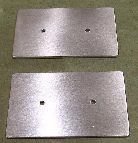 I sanded the surfaces of the (E-01414) elevator counterweights and cleaned them with Southern Polyurethanes Incorporated (SPI) 700-1 wax and grease remover in preparation for priming. |
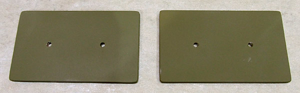 The (E-01414) elevator counterweights were primed with Tempo A-702 Valspar green primer. |
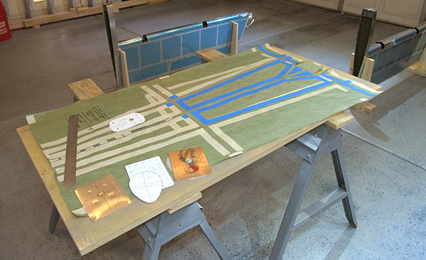 I am laying out a template for the installation of our WAAS GPS antennas that will be placed on the dorsal portion of the fuselage. |
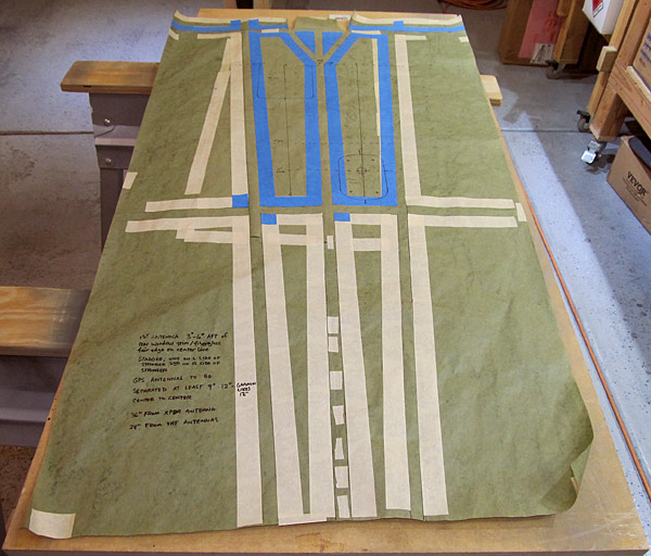 According to the Garmin® guidelines, the first antenna should be placed between 3"-6" aft of the rear window edge or trim line along the fuselage centerline left of the stringer. The second antenna should be stagger mounted on the opposite right side of the stringer and at least 9"-12" from the center of the first antenna, Garmin® prefers 12", and at least 36" from a transponder antenna and 24" from a VHF antenna. |
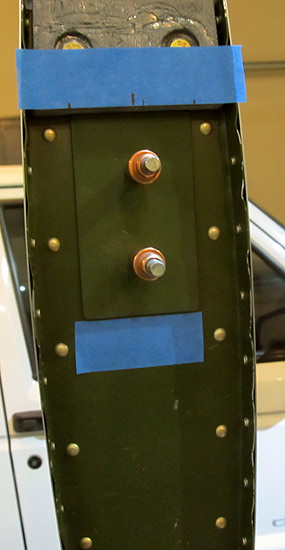 As per step sixteen, on page nine, of Service Bulletin SB-00043, the (E-01414) counterweight was positioned immediately aft of the (E-614) counterweight on the right inboard side of the left elevator tip as per figure thirteen. |
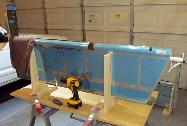 Here is a wider shot of what is being done... |
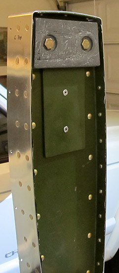 The (E-01414) counterweight was temporarily removed, the holes were deburred, and then the (E-01414) counterweight was reclecoed into position. |
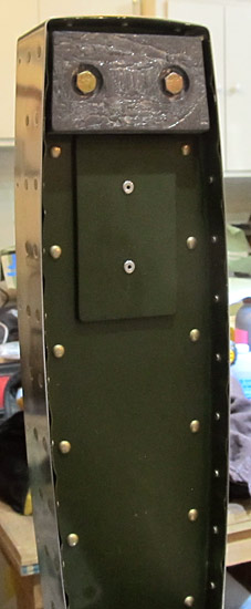 Steps fifteen through nineteen were repeated for the right elevator tip. |
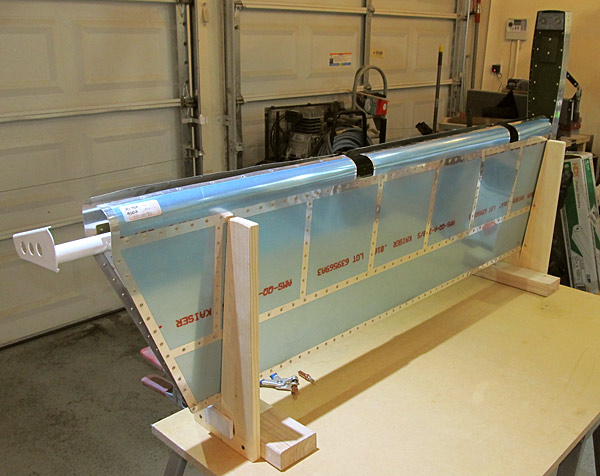 This is the right elevator. |
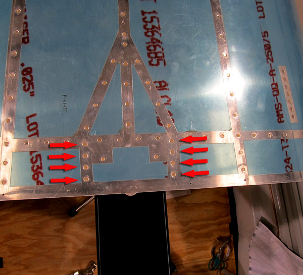 As per step two, on page 37-07, referencing figures two and three, I riveted the (F-01432B-L and F=-01432B-R) left and right roll bar brace brackets to the (F-01475) aft fuselage top skin, (F-01475A) skin doubler, and to the (F-01406C) bulkhead. |
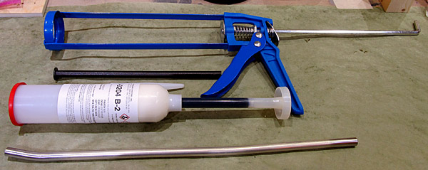 This is the caulking gun, (the one that Van's sells at their store), plunge mixing stick, (MC-236-B1/2) fuel tank sealant, and 3/8" x 15" aluminum tube that is going to be used to apply the tank sealant to the rear spars and elevator skin joints. |
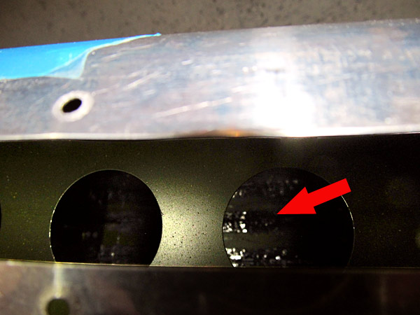 As per step fourteen, on page seven, of service bulletin SB-00043, a fillet of (MC-236-B1/2) fuel tank sealant was applied to the upper and lower skins where the (E-10007 and E-00907) rear spars meet the elevator skins. |
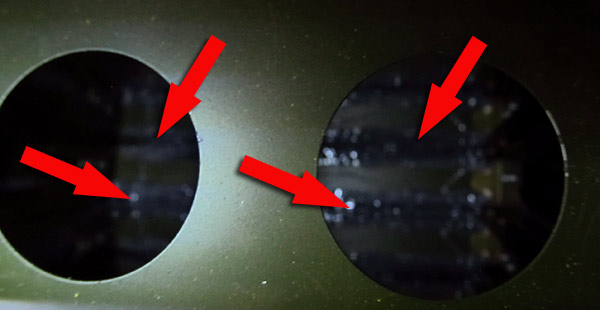 This is another view... |
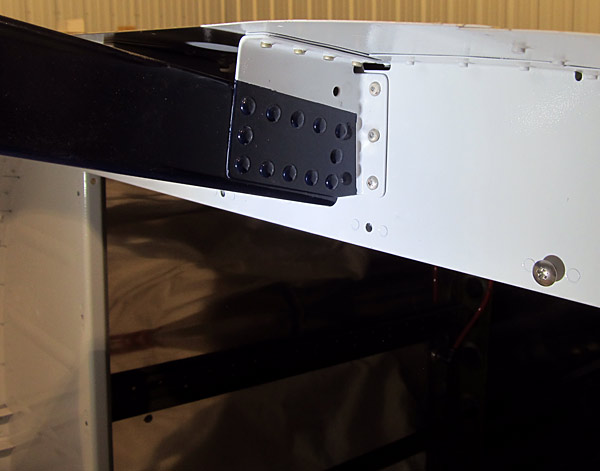 As per step two, on page 37-07, referencing figures two and three, I riveted the (F-01432B-L and F-01432B-R) left and right roll bar brace brackets to the (F-01406C) bulkhead using the Van's Aircraft Tech support approval to use CherryMax® CR3213-4-3 rivets in the three holes on each side. |
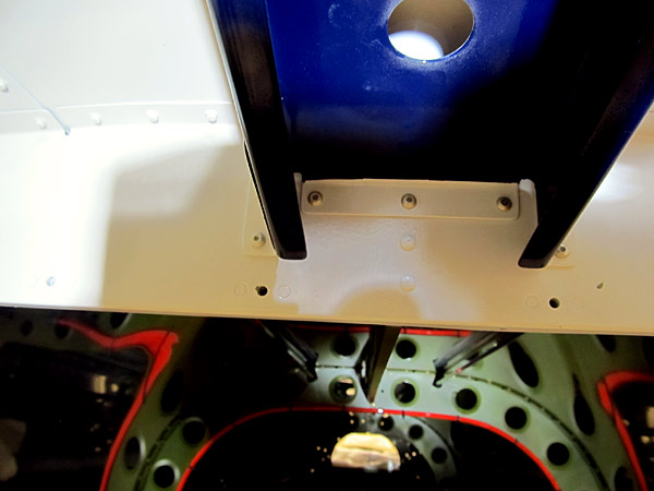 As per step three, on page 37-07, referencing figures two and three, I riveted the (F-01432A) roll bar brace to the (F-01406C) bulkhead using the Van's Aircraft Tech support approval to use CherryMax® CR3213-4-4 rivet in the center hole, and CR3213-4-3 rivets in the left and right holes. |
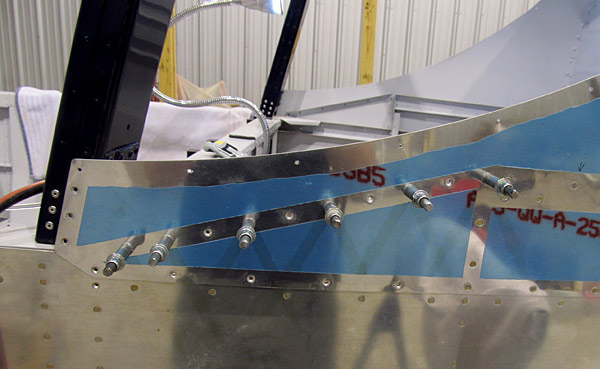 As per step four, on page 37-08, referencing figure two, the (F-14125-L and F-14125-R) left and right skin stiffeners were clecoed to the (F-01470-L and F-01470-R) left and right fuselage side skins and the (F-01474-L and F-01474-R) left and right aft fuselage top side skins as shown in figure two. |
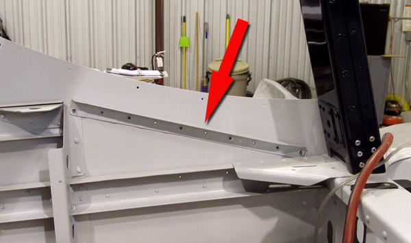 This is the inside view of the (F-14125-L) left skin stiffener that will be riveted... |
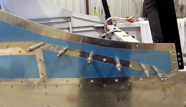 This is the right outside view of where the stiffener is. |
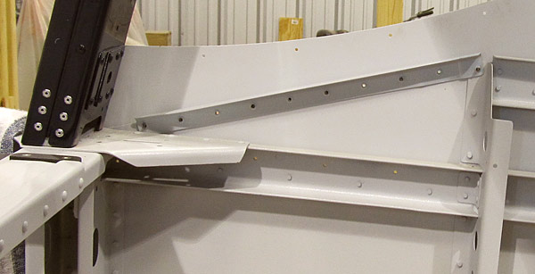 This is the inside view of the (F-14125-R) right skin stiffener that will be riveted... |
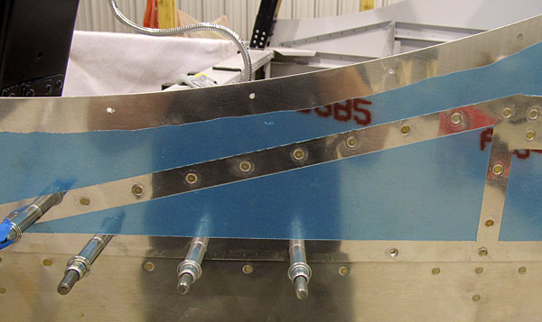 As per step five, on page 37-08, referencing figure two, I riveted the (F-14125-L and F-14125-R) left and right skin stiffeners to the (F-01474-L and F-01474-R) left and right aft fuselage top side skins and the (F-01470-L and F-01470-R) left and right fuselage side skins using AN426AD3-4.5 rivets in place of the called out AN426AD3-4 rivets, and also using AN426AD3-5 rivets in place of the AN426AD3-4.5 rivets called for. |
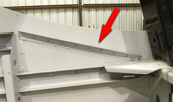 This is the inside view of the (F-14125-L) left skin stiffener that was riveted... |
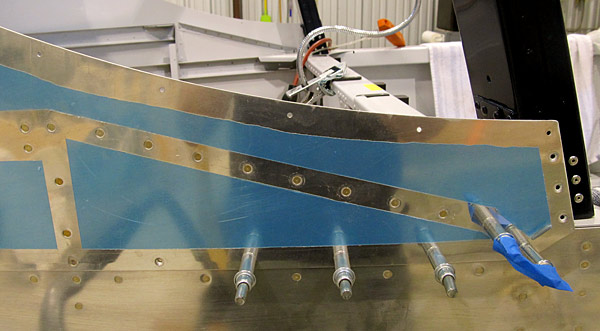 This is the outside view of the (F-14125-R) right skin stiffener that was riveted... |
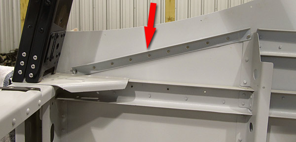 This is the inside view of the (F-14125-R) right skin stiffener that was riveted... |
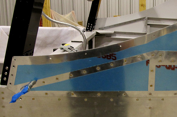 As per step six, on page 37-08, referencing figure two, I riveted the (F-01474-L and F-01474-R) left and right skins to the (F-01418A-L and F-01418A-R) left and right forward mid fuselage longerons using hardware called out in figure two and making sure to leave the forward most hole open as shown in figure two. |
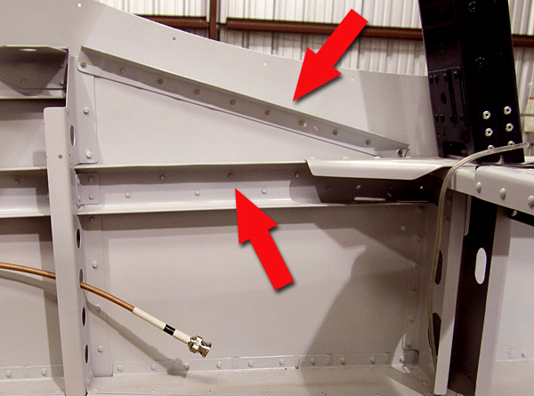 This is the left fuselage inside view... |
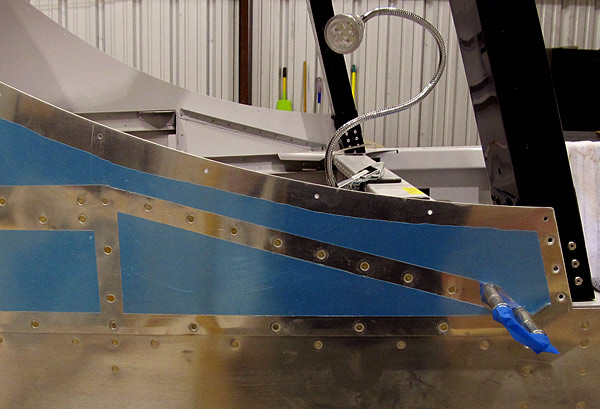 This is the right outside fuselage view... |
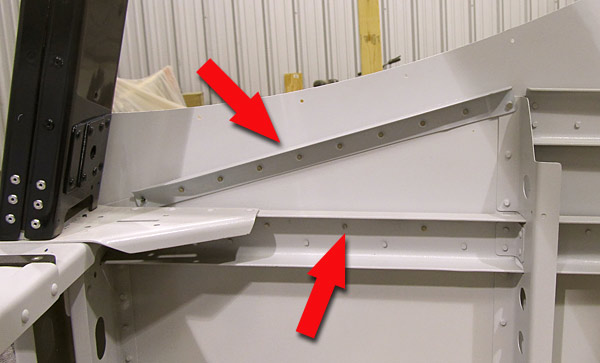 This is the right inside fuselage view... |
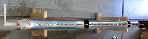 As per step fifteen, on page nine of service bulletin SB-00043, I clecoed the leading edges of the upper to lower elevator skins of the left and right elevators so that they can be re-riveted together. |
 The leading edges will be riveted together with these AD-41-ABS rivets. |
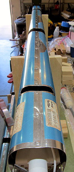 The left elevator is done having it's leading edge riveted. |
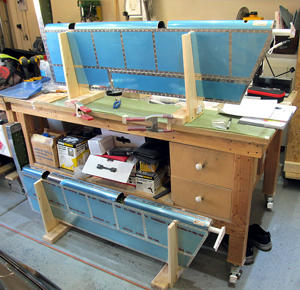 Now both the left and the right elevators have the leading edges re-riveted together with the AD-41-ABS rivets. |
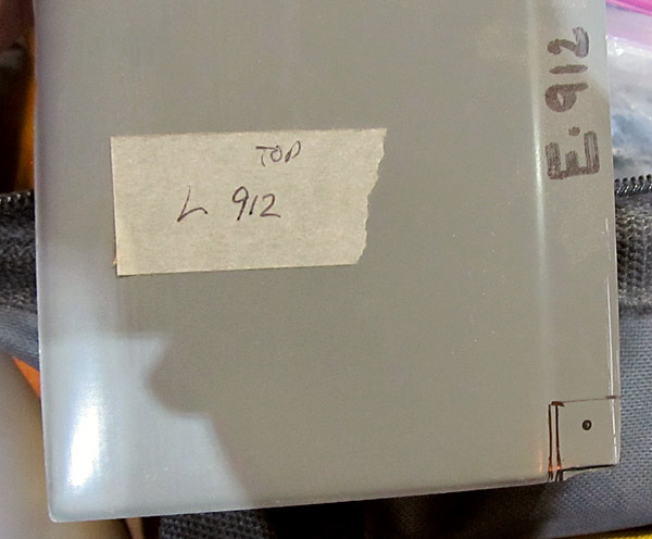 As per step six, on page 12-05, referencing figure three, the aft flange edge on the (E-912-L and E-912-R) left and right elevator tip fairings need to be trimmed between the flange and the entire elevator trailing edges so that they can be fully inserted into the tip of the elevators. |
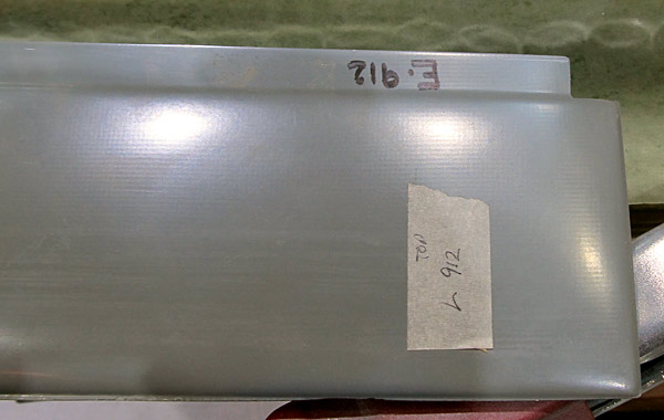 I cut the notch out with a hand held, fine toothed, back saw and then sanded the cuts with sandpaper. |
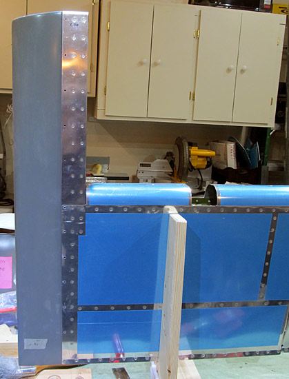 This is the (E-912-L) left elevator tip fairing fitted to the left elevator. |
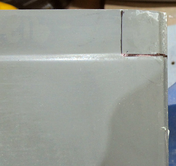 This is the notch area laid out for the right elevator, this is the (E-912-R) right elevator tip fairing. |
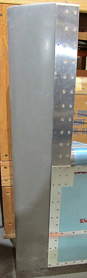 This is the (E-912-R) right elevator tip fairing fitted to the right elevator. |
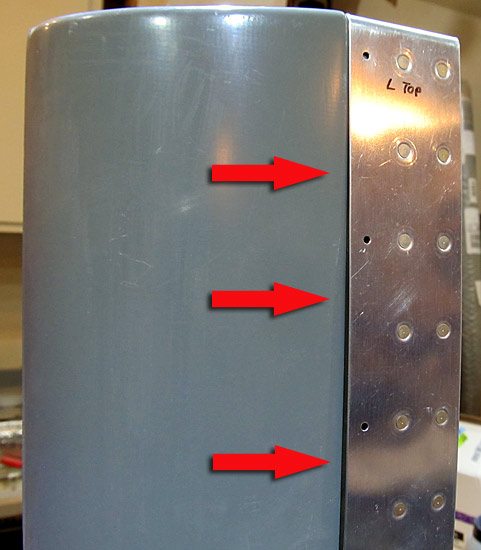 The left and right elevator tip fairings are not fitting well. |
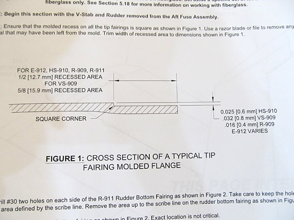 As I mentioned above, the shoulders on the flanges need to be "squared up" as per step one, on page 12-02, figure one, (shown here), and about 0.025" (6mm) in depth. Hopefully it will improve the fit somewhat... |
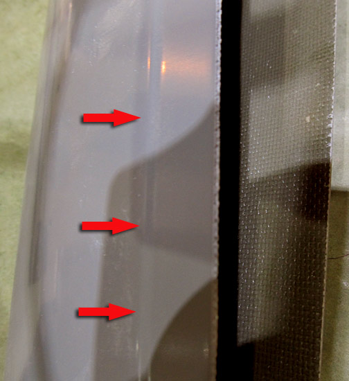 These are the flanges that I am refering to. |
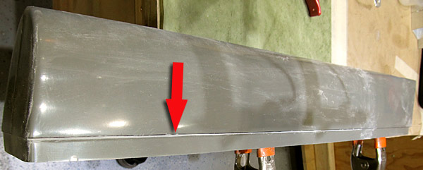 I have started the "squaring up" process by using a small file and running it along the length of the fairing. This is going to be a slow process! |
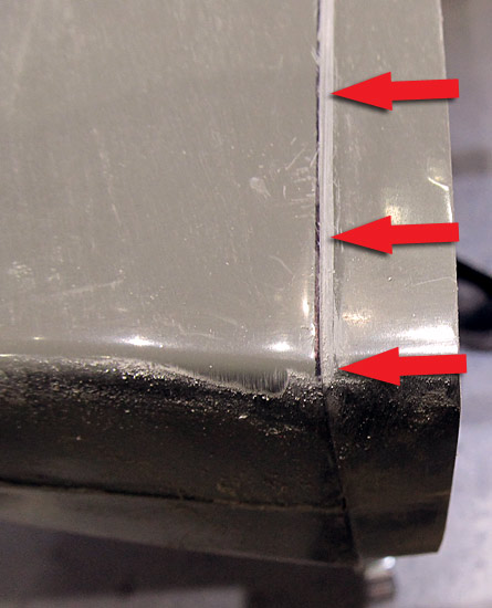 Here is a closer look at the flange, some of the fibers of the glass are beginning to show, I dare not go much further, I'll need to run some resin over these later... |
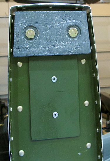 Up until now the (E-614) lead elevator counterweights have been unprimed and they need to be painted. |
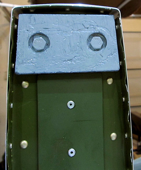 I primed the (E-614) lead elevator counterweights with Southern Polyurethanes Incorporated (SPI) 6610-4 gray epoxy primer. This is the portion that will be seen. |
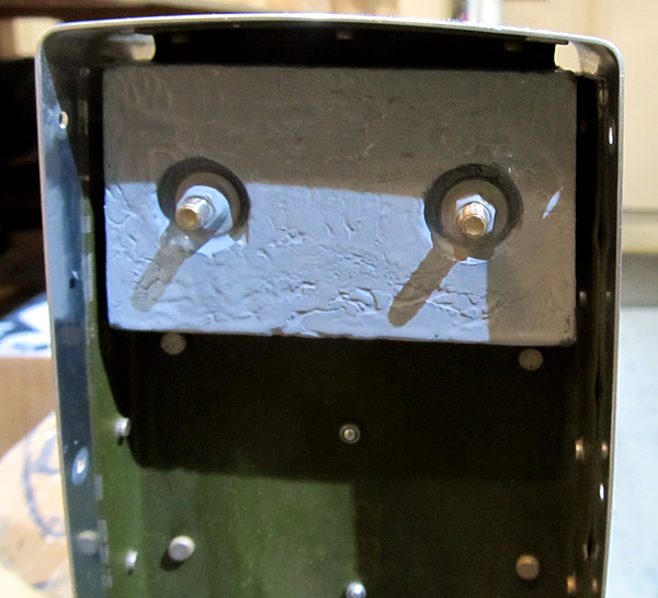 This is the elevator counterweight outside half that will be hidden by the elevator tip fairings. |
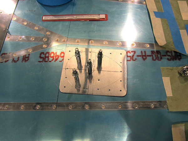 I laid out where the GPS antennas will be placed on the dorsal portion of the fuselage. |
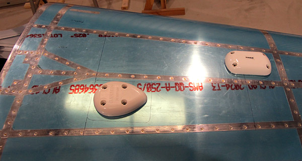 According to the Garmin® guidelines, the first antenna was placed more than 6" aft of the rear window edge, along the fuselage centerline, left of the stringer. The second antenna was stagger mounted on the opposite right side of the stringer and 12" from the center of the first antenna. |
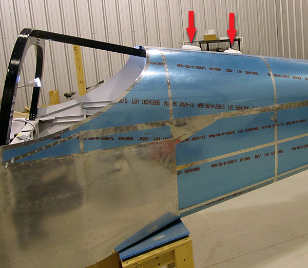 Here's what it looks like from the side... |
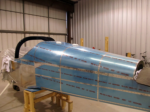 Here's what it looks like from behind... |
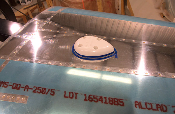 I removed the protective blue vinyl from the dorsal section of the fuselage where the GPS antennas will be installed and cleaned the skin in preparation for permanant installation and sealing of the antennas. |
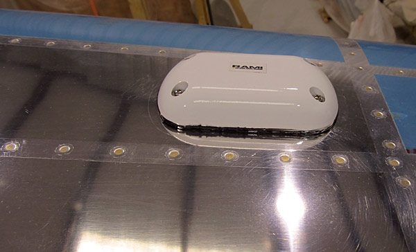 This is the RAMI® AV-801 WAAS GPS antenna. |
 This is what the tube of DAP® Dynaflex 230 looks like, it is a premium waterproof sealant for windows, doors, siding, and trim. With silicone-like toughness, it withstands the elements while offering outstanding durability, adhesion, and flexibility. It is available in clear, white, and black. |
 Next, I want to label the RG-400 coax cable that I will run from the antennas to the instrument panel. |
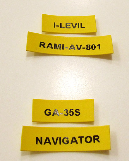 Here are the heat shrink labels that I created for the coax cables. |
 I used Aonomi 3/8" A18054 yellow heat shrink tube label cassettes. (There are different sizes available.) |
 Here is the part number for the 3/8" yellow shrink tube labels that I found, They are a "cheaper" alternative label for the DYMO D1 labels recommended for the DYMO® LabelManager® 160. Although not as robust as the DYMO D1 labels, they are still quite good. |
 As I reported earlier, I am unhappy as to how "ill fitting" the Van's Aircraft stock elevator tip fairings are for the RV14A. I know that these fairings are "sub contracted out" and have been around for a long time, but there has to be something better fitting than these... |
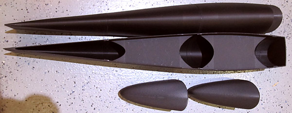 I ordered the Horizontal Stabilizer and Elevator Tip Fairings kit and here is what I got. |
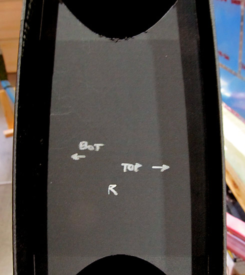 These fairings are made from PETG (Polyethylene Terephthalate Glycol), a thermoplastic polyester that weighs considerably less than the stock fairings and they have advanced UV inhibitors contained within them. |
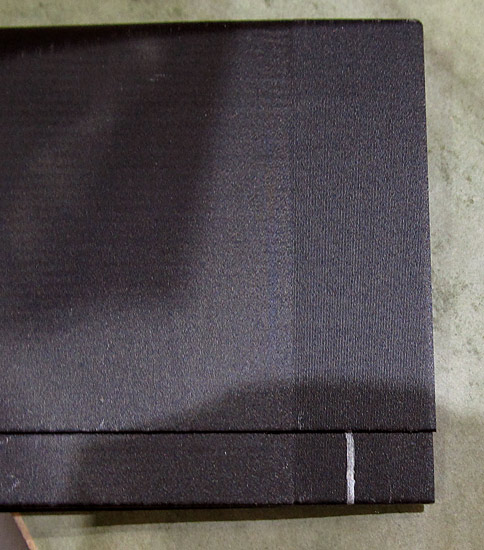 As per step six, on page 12-05, referencing figure three, the new (E-912-L and E-912-R) left and right elevator tip fairings were marked at the aft flanges so that they can be trimmed to remove material that would prevent them from being fully inserted into the end of the elevator. |
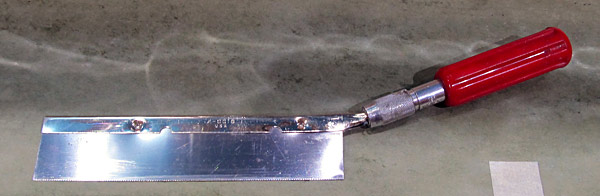 I am going to make the notch cut with this fine tooth modeler's back saw. |
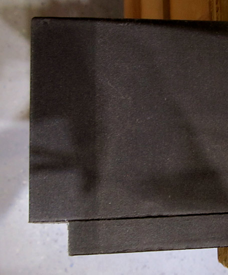 The "notch" literally only took 11 minutes to mark and cut, something that I really appreciate, because today it is 95°F in the shop! |
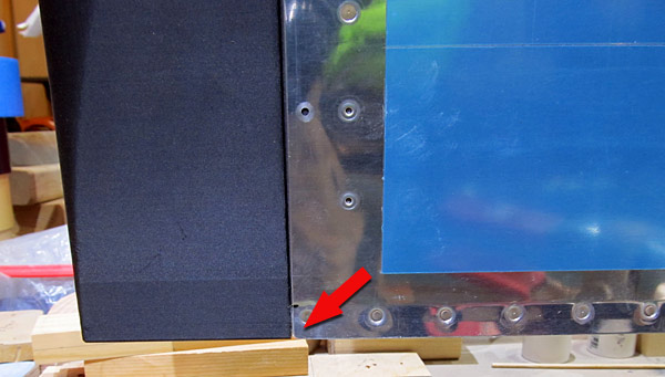 The (E-912) fit snuggly into place after the "notch" was cut and take a look at how well it is aligned with the trailing edge of the elevator! I literally did nothing but cut the "notch". The leading edge, side edges, and trailing edge fit perfectly! |
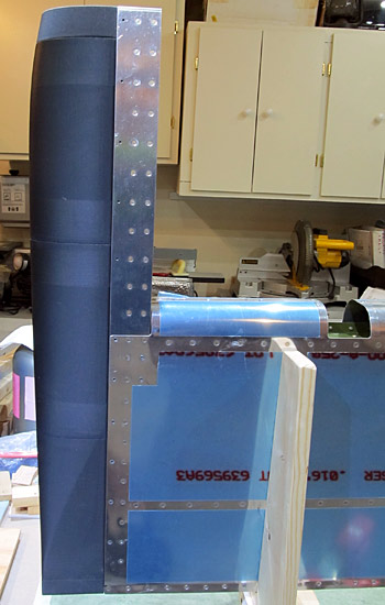 Here is a better look at the overall fit. The elevator tip is only held in position by friction here but look how even all of the gaps are.... |
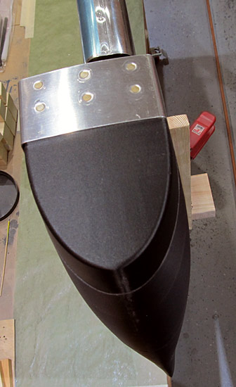 Take a look at how great this leading edge "cap" looks! |
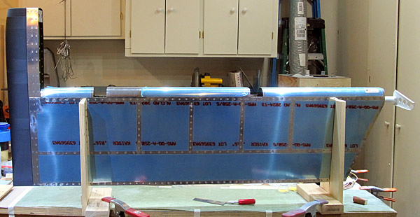 This is the right elevator fitted with the new fairings... |
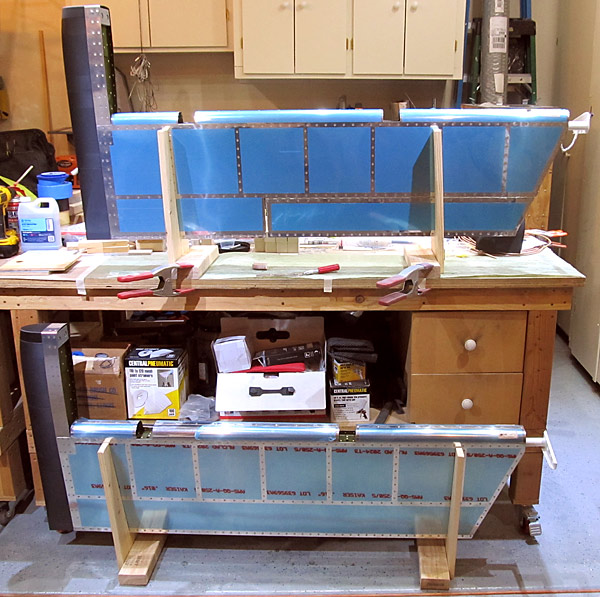 These are both elevators fitted with the new fairings, again, this is just friction holding them on, drilling, clecoing, and final preparation for riveting to go... |