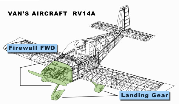
Landing Gear And Firewall Forward
|
Van's Aircraft offers several engines that can be used on the RV14A and RV14 aircraft. We will be using the Lycoming YIO-390 A3B6 standard engine of 210 H.P.
|
|
Van's Aircraft offers several engines that can be used on the RV14A and RV14 aircraft. We will be using the Lycoming YIO-390 A3B6 standard engine of 210 H.P.
|
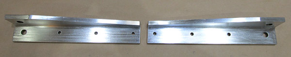
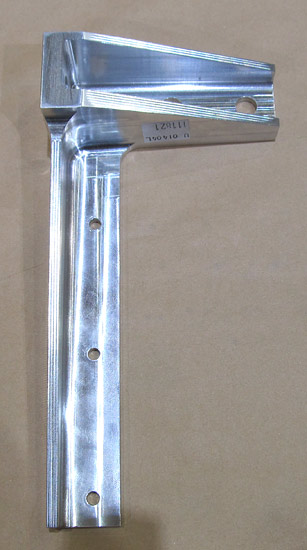
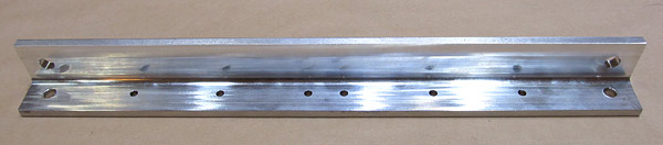 As per step three, on page 40A-02, of the builder's manual and using the dimensions provided in figure two, the (U-01405) gear attachment angles have to be fabricated. |
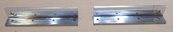
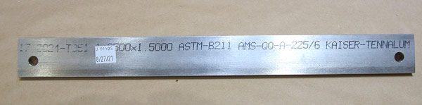 They are fabricated from this piece of 2024-T351 aluminum angle stock which is 1 1/2"x 1 1/4"x 1/4" thick and roughly 15 3/16" long. |
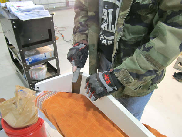
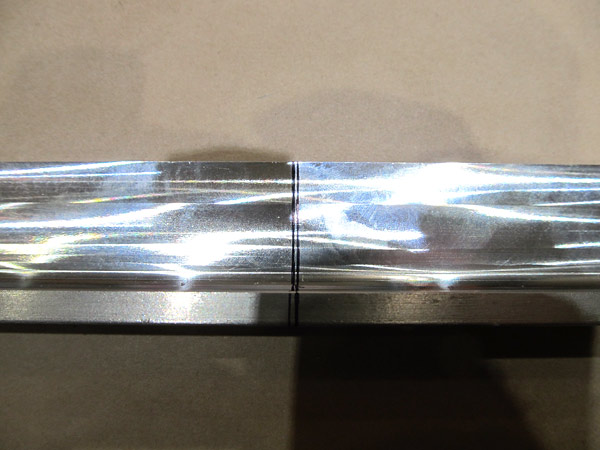 Each angle brace is 7 9/16" long and as you can see from the lay-out lines there isn't going to be much room for messing up the first cut to separate the angle into two. |
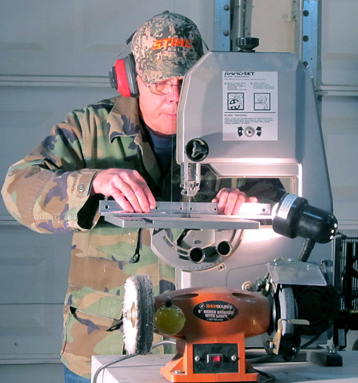 I used our bandsaw to cut the aluminum angle stock in half. |
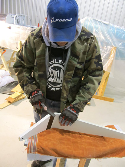
 Okay, the first cut is done now and next a diagonal line has to be laid out on each piece and cut. |
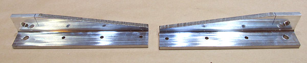 I cut the diagonals using the bandsaw and cut a little short of the lines and will clean up the pieces with a file. |
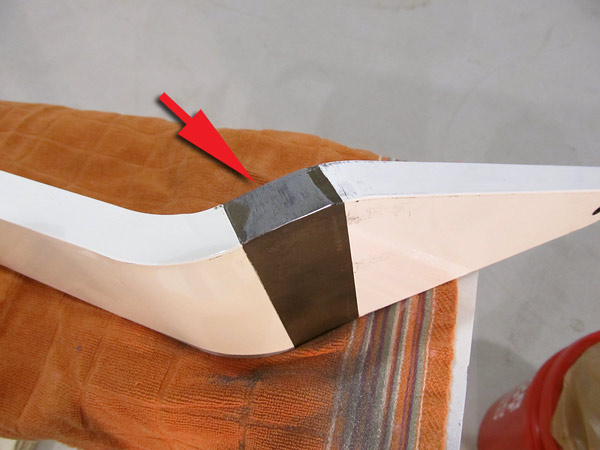
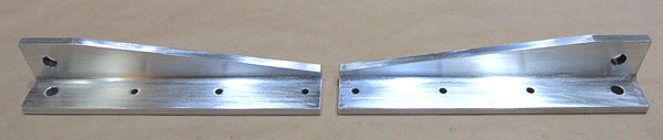 The file work took a little time but the (U-01405_L and U-01405-R) gear attachment angles are ready to be prepared for priming. |
 I used some 320 sandpaper, lightly sanded the surfaces, and then washed the parts with acetone. |
 Nice! |
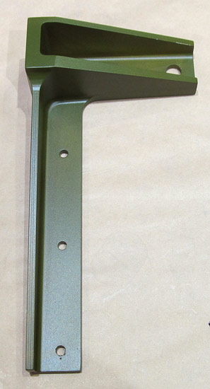
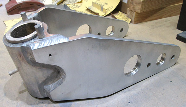
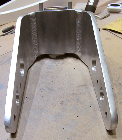
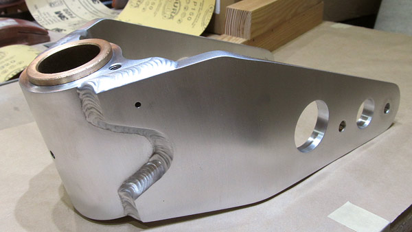
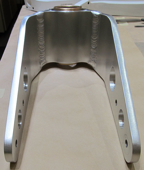
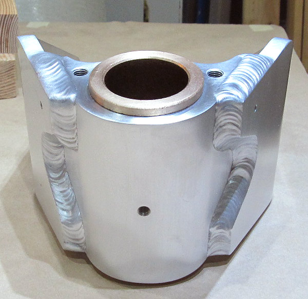
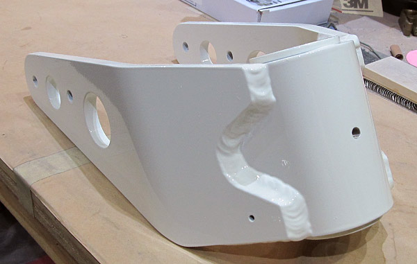
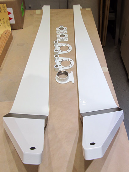
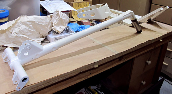
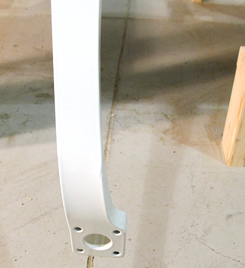
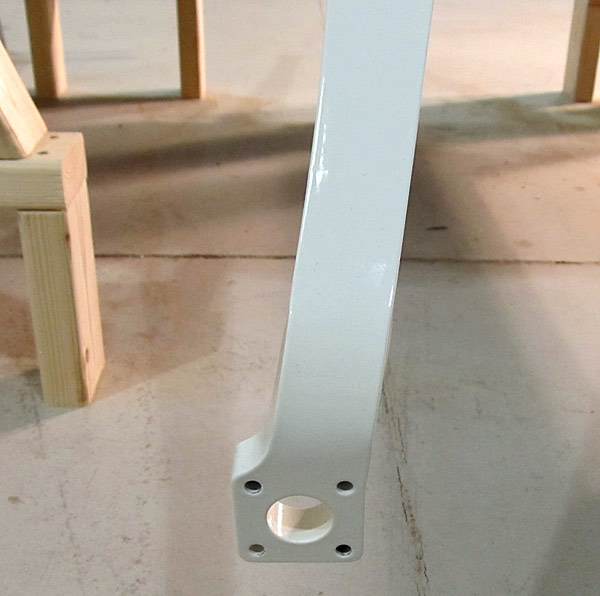
 These are the (U-01404-L and U-01404-R) upper landing gear braces. |
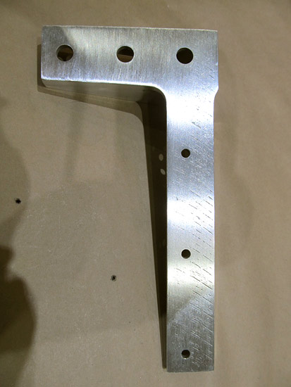 I noticed some deep milling marks on the (U-01404-L) left upper landing gear brace so I called Van's Aircraft to see if it was okay to use this part. |
 I started the deburring process on the (U-01404-R) right upper landing gear brace and preparation for priming as per step three, on page 40A-02 of the builder's manual. |
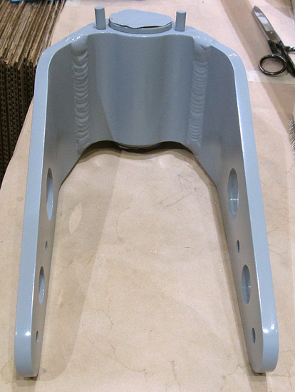
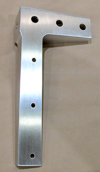 Some light sanding with 320 grit sandpaper and a wash down with acetone and this piece is ready for Priming! |
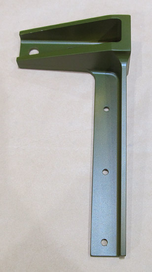 I primed the (U-01404-R) right upper landing gear brace with Tempo A-702 Valspar zinc phosphate self-etching green primer. |
|
|
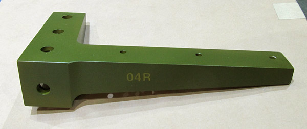
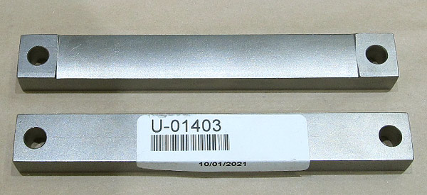 The (U-01403) gear attachment bars were next to be prepared for priming. |
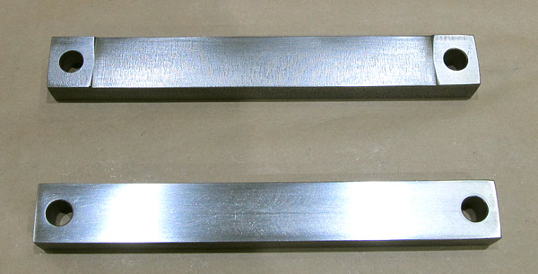 Ready for priming! |
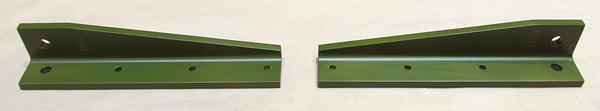
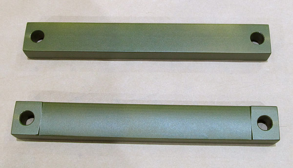 I primed the two (U-01403) gear attachment bars with (Tempo) A-702 Valspar zinc phosphate self-etching green primer. |
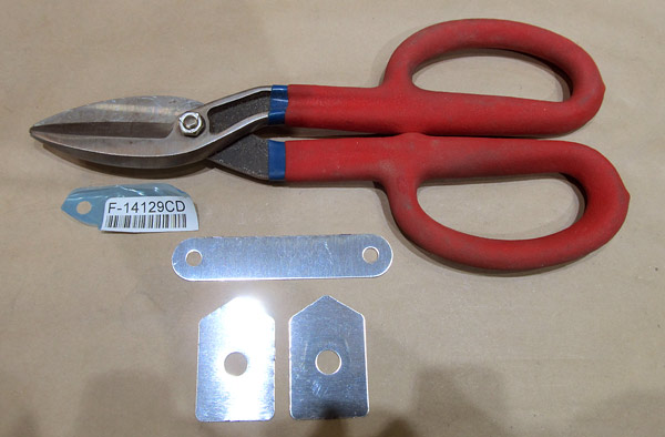
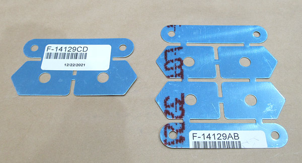 As per step one, on page 40A-04, figure one and two of the builder's manual, locate the (F-14129AB and F-14129CD) gear shims and separate them into individual parts. |
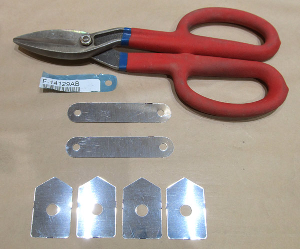 I used the straight cutting shears to make the rough cuts in separating the individual pieces and will use a file to final size and debur the pieces. |
 I used the straight cutting shears to make the rough cuts in separating the individual pieces and will use a file to final size and debur the pieces. |
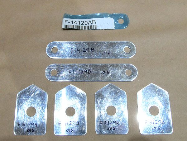 The (F-14129A and F-14129B) shims have been deburred and labeled. |
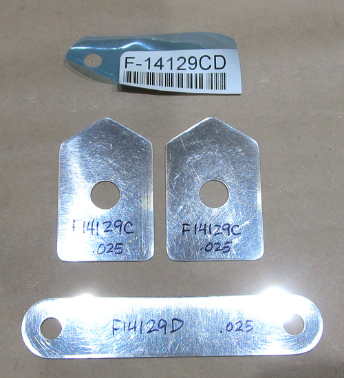 The (F-14129C and F-14129D) shims have been deburred and labeled. |
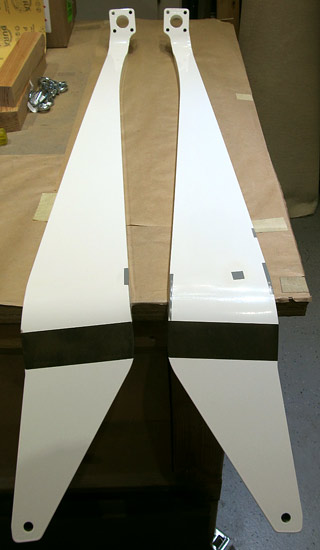
 I received the replacement (U-01404-L) upper landing gear brace from Van's Aircraft and thankfully the quality on this one is much better than the first one I received. |
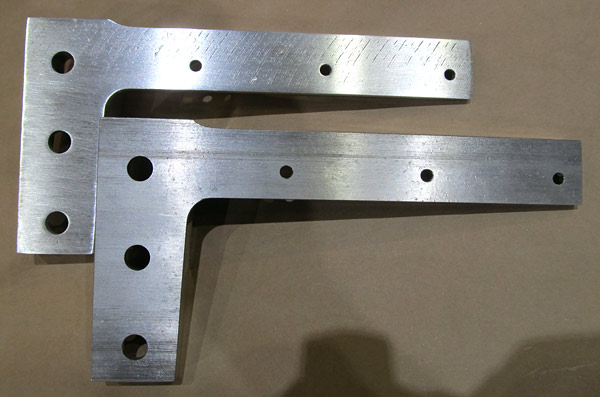 Here is a side-to-side comparison of the old (U-01404-L) (top of photograph), and the new (U-01404-L) (bottom of photograph). |
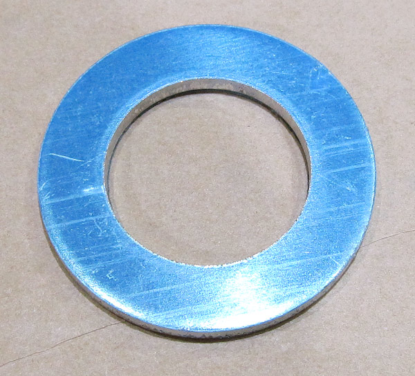 This is an (U-1002) isolator washer. |
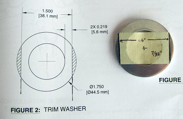 As per step four, on page 40A-05 of the builder's manual, and referencing dimensions in figure two, excess material is to be removed from the (U-1002) isolator washer. |
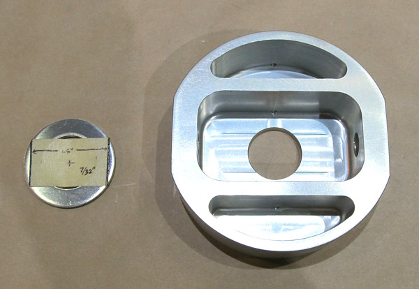 The (U-1002) isolator washer is supposed to be able to fit down inside of the (U-01407) elastomer pad as seen in figure one, on page 40A-06 of the builder's manual. |
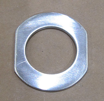 The (U-1002) isolator washer was lightly sanded and prepared for priming. |
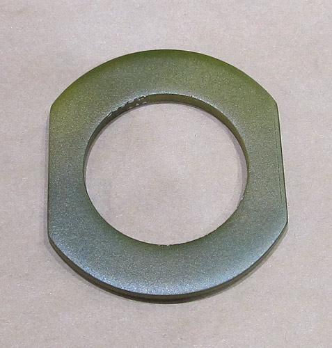 I primed the (U-1002) isolator washer with Tempo A-702 Valspar zinc phosphate self-etching green primer. |
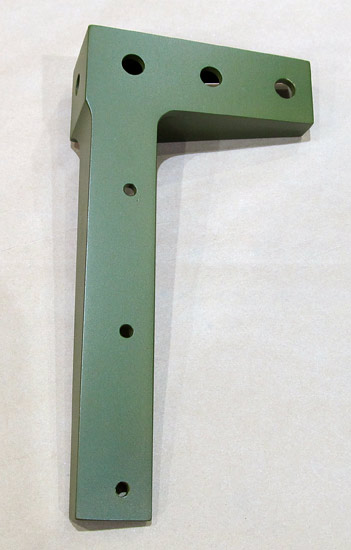
 The (U-01404-L) left upper landing gear brace was deburred, the surfaces lightly sanded, and washed with acetone in preparation for priming. |
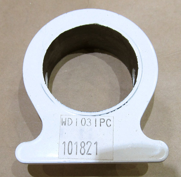 This (WD-1031) axle flange will be used in step two, on page 40A-07 of the builder's manual, as a guide to drill a (.313", which is 5/16") hole into the spindle of the (U-01406) nose gear leg. |
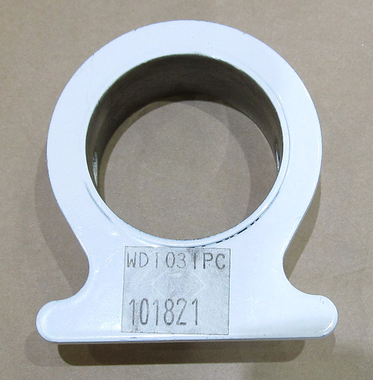 I removed the excess powder coating on this (WD-1031) axle flange. |
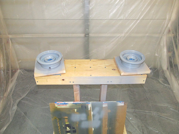
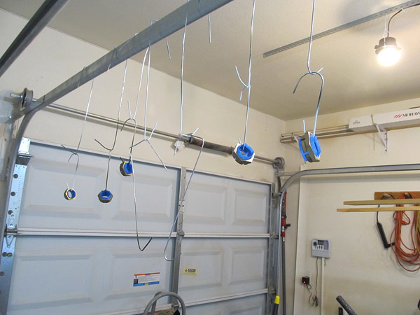
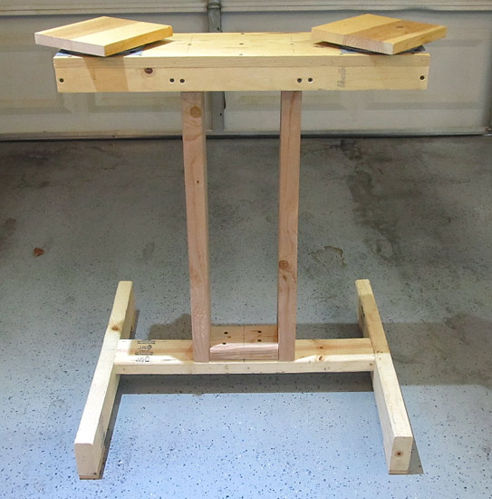 The landing gear wheels will be painted soon so I made this stand to place the rims on while they are being painted. It has two pads with "lazy susan" hardware installed so that the wheel rim can be rotated while painting. |
 As per step 1, on page 40A-05, and figure 1 of the builder's manual, several holes have to have powder coat removed from the (U-01406) nose gear leg. |
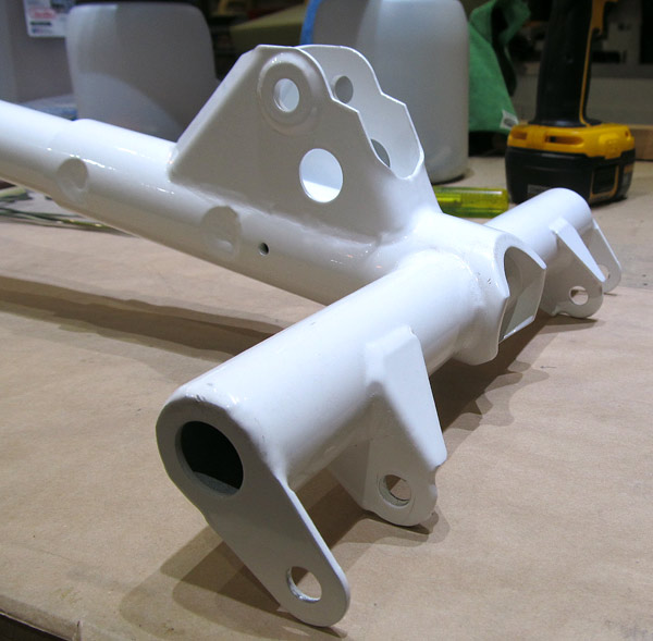 These holes on the (U-01406) nose gear leg need the powder coat removed too. I used 3/8", 7/16" drill bits as well as some sandpaper to remove the powder coat. |
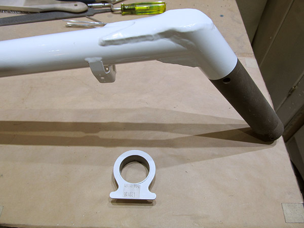 The (WD-1031) axle flange needs to be slid onto the spindle of the (U-01406) nose gear leg and as per step 2, on page 40A-07, referencing figure 1, final drill the hole to (.313") using the axle flange holes as a guide. |
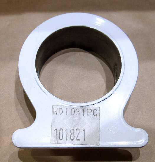 This is the (WD-1031) axle flange. |
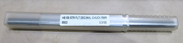 I used a (.313") reamer to final size the hole, this keeps the hole perfectly round. |
 Be careful to note the proper orientation of the (WD-1031) axle flange on the (U-01406) nose gear leg. |
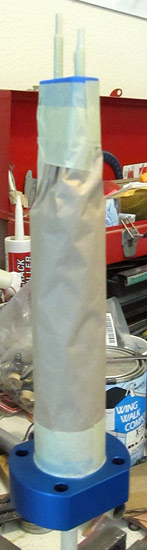
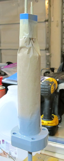
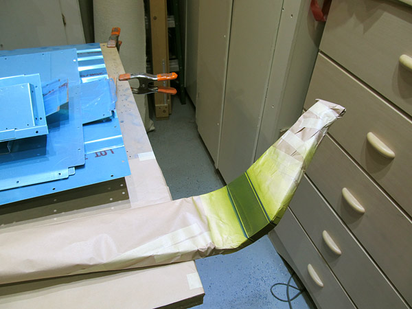
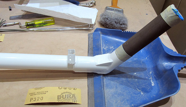 I taped the ends of the (U-01406) nose gear leg so that the threads and powder coat would not be damaged because the spindle needs to be sanded and polished next. |
 As per step 2, on page 40A-07, and figure 1, the spindle of the (U-01406) nose gear leg was sanded with 320 grit sandpaper and polished. |
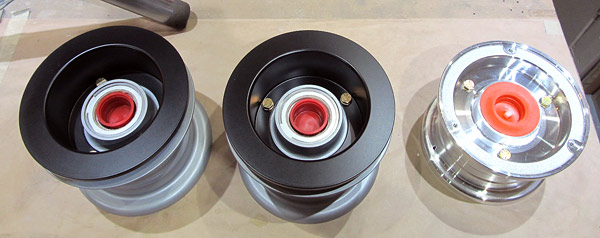
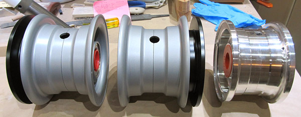
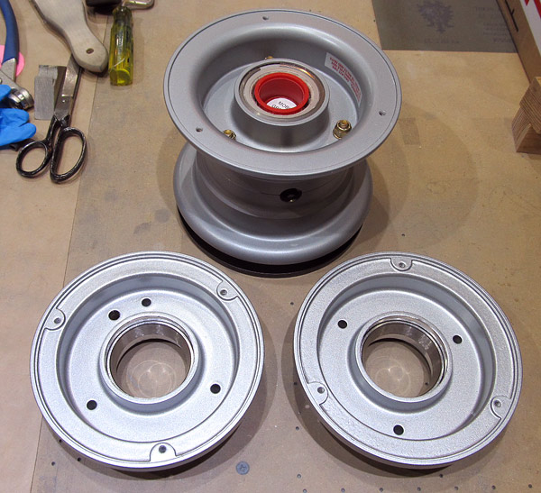
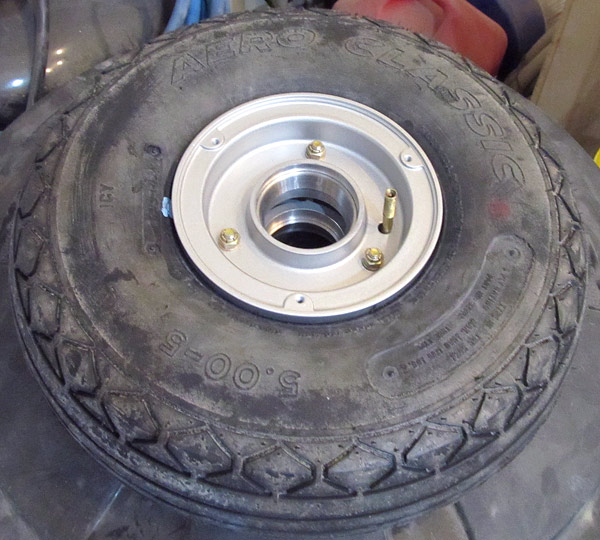
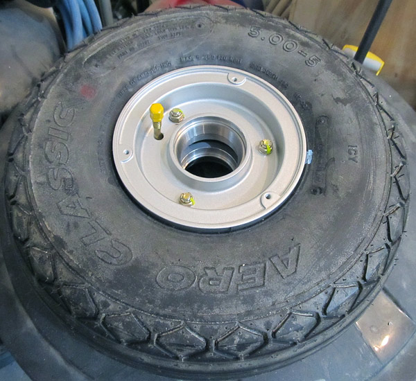
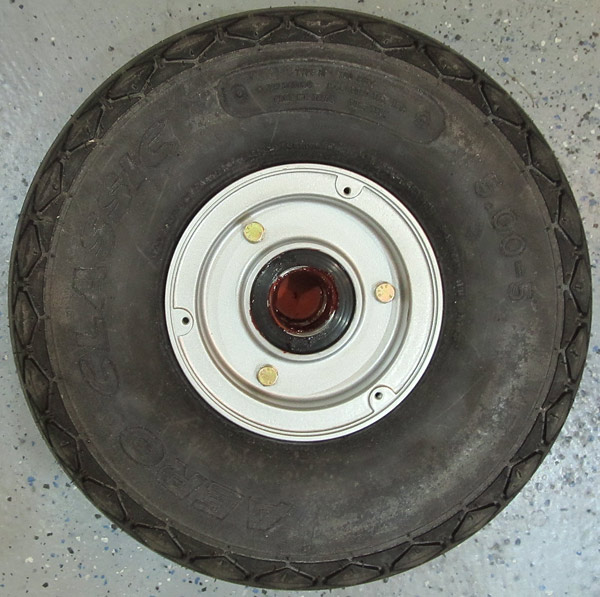
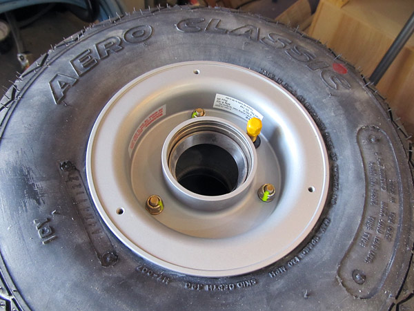
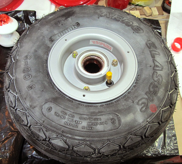
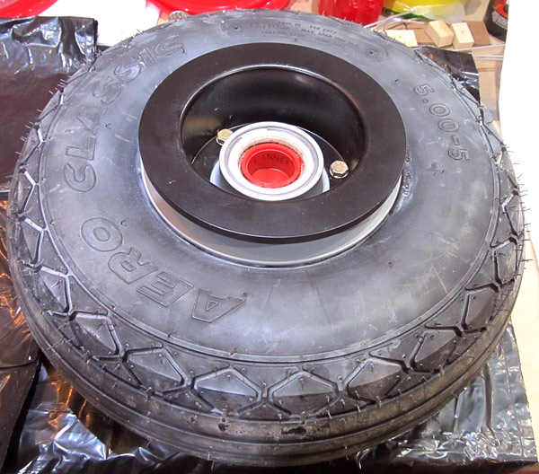
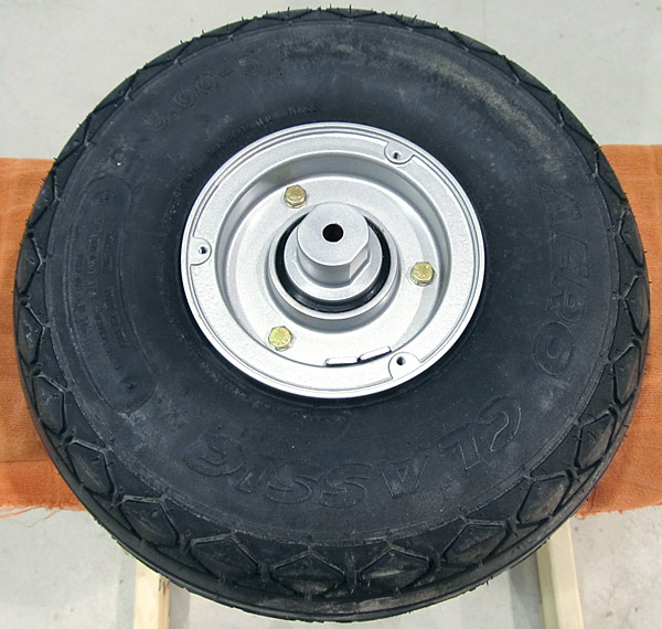
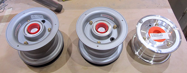 These are the wheels that come standard with the RV14A kit. |
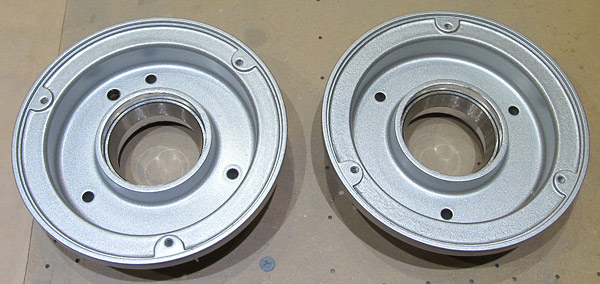
 This is what the back side of the wheels look like. |
 This is what the sides look like. |
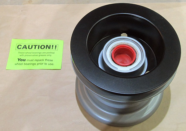
 The wheels need to be disassembled in order that the tubes and tires be mounted to them, I am starting with the Matco (NW501.25) since it will need to be prepared for painting before I mount the tires. |
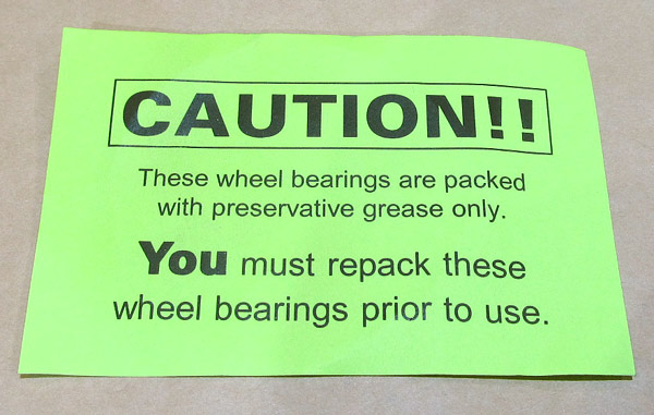
 The Matco (NW501.25) nose wheel has been disassembled and it should be noted that the wheel bearings will need to be repacked before using the nose wheel. |
 Matco NW501.25 disassembled. |
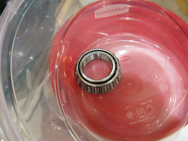
 These are the Matco wheel bearings that are to be cleaned and repacked with wheel grease. |
 I cleaned the Matco nose wheel with soap and water and scuffed the surfaces with red Scotch Brite pad in preparation for painting with epoxy primer. |
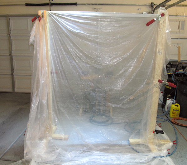 I assembled a small paint booth in order to paint the Matco nose wheel. Nothing fancy here, just a small booth to paint some small items. |
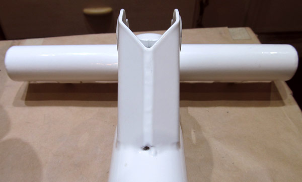
 I am using the homemade paint stand to paint the Matco nose wheel with epoxy primer. |
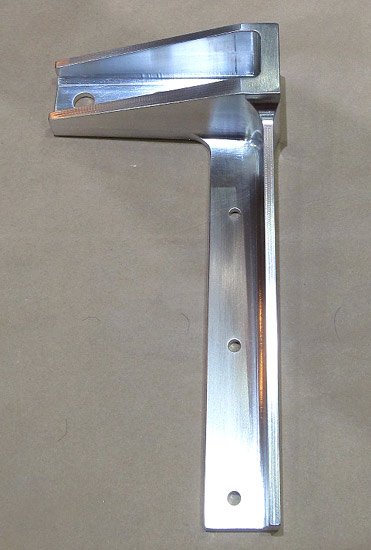
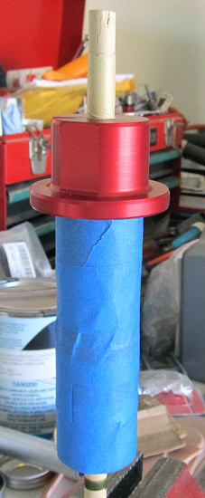
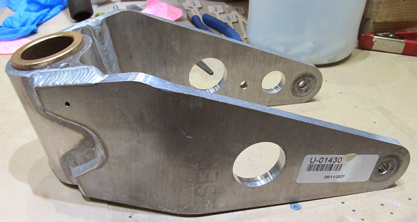 This is the (U-01430) nose wheel fork. I need to get it ready for priming. I am using several grits of sandpaper to get it ready, starting out with 150 grit and ending up with 400 grit. |
 As you can see there are a lot of curves, it's going to take awhile to get it ready.... |
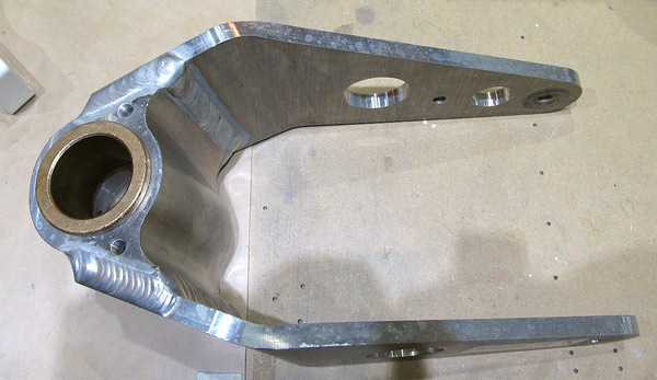
 I plugged up the holes with dowel rods so that I didn't get any dust and grit inside them. |
 I painted the Matco nose wheel rims with VHT high temp engine "cast aluminum" silver (SP995) enamel. |
 I have used the VHT paint before, it lasts pretty well, and from a distance it's a pretty close match and of course, the wheels pants will cover most of the wheel anyways. |
 Back to sanding the (U-01430) nose wheel fork..... |
|
|
|
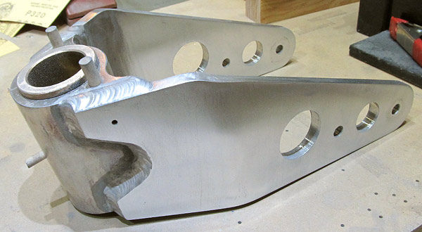
 Finally! The (U-01430) nose wheel fork is ready for priming, after I washed it with soap and water and a light scuffing with a red Scotch Brite pad. |
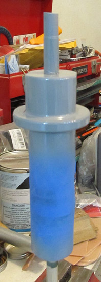
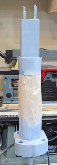
 I primed the top half of the (U-01430) nose wheel fork with SPI (6610-4) gray epoxy primer. |
 I finished priming the (U-01430) nose wheel fork with SPI (6610-4) gray primer. |
|
 The (U-01401-L and U-01401-R) left and right main landing gear legs had some chips in the powder coat so I sanded them and primed them with the SPI primer. |
 I topcoated the (U-01430) nose wheel fork with UTECH 500 Insignia White (S60385) paint. |
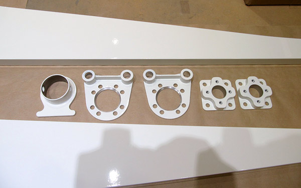
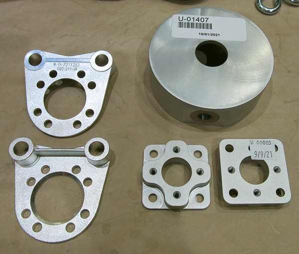 I want to paint the (U-01407) elastomer pad, (U-00003) bracket mounts, (W/0-2211252 20-211-1R) and (W/02112521 020-211-1R) brake torque plates so I am lightly sanding them in preparation for priming. |
 I primed the above parts and the spots on the main landing gear legs with SPI (6610-4) gray primer. |
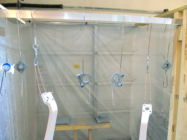
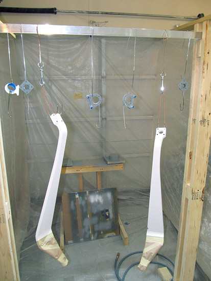 The parts have all been primed and now it's time to topcoat them with Insignia White paint. |
 I painted the (U-01401-L and U-01401-R) main landing gear legs, the (JU-01407) elastomer pad, the (U-00003) bracket mounts, the (W/0-211252 020-211-1R and W/0-21125221 020-211-1R) brake torque plates with UTECH 500 (S60385) Insignia White paint. |
 They turned out pretty nice! |
|
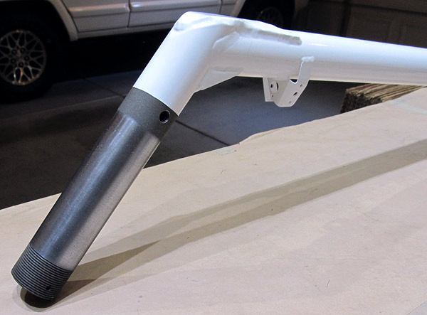
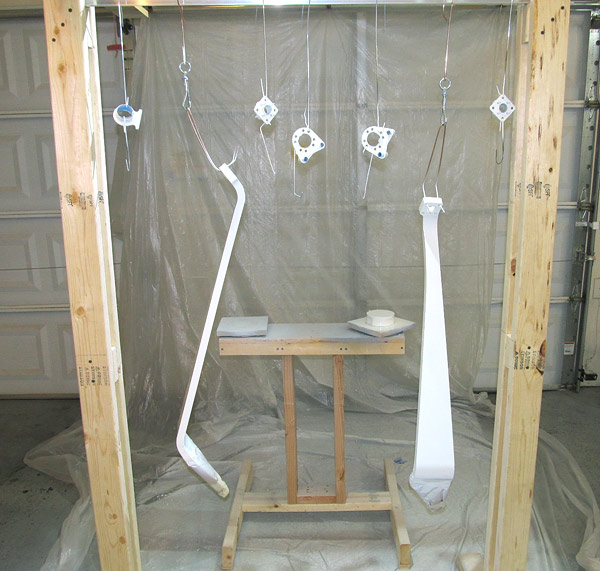
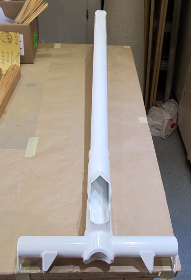 I want to paint the lower half of the (U-01406) nose gear leg Insignia White so that it matches the rest of the landing gear parts. |
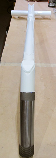 I painted the (U-01406) nose gear leg with UTECH 500 (S60385) Insignia White. |
 Here is another view. |
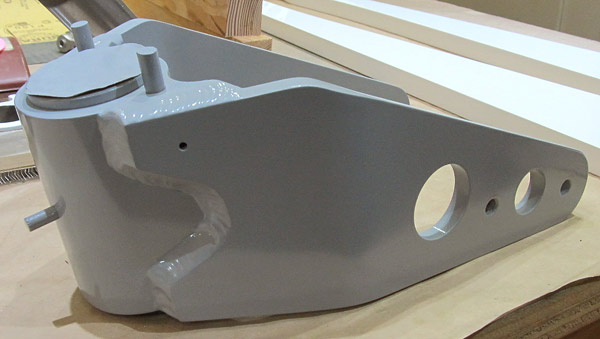
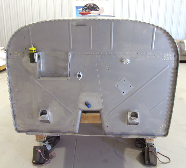 As per step 1, on page 40A-02, figure 1, there are six holes that the (FF-01400) engine mount bolts to the airframe at the firewall. These need to be final sized to (.375"). |
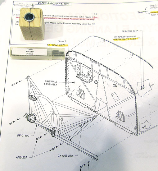 *There is a note in the instructions that says to be careful to ream the six holes perpendicular to the firewall. |
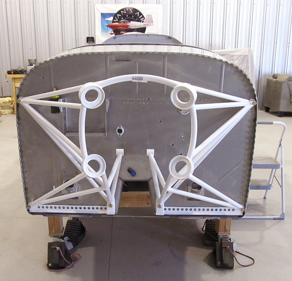 The mounting holes in the (FF-01400) engine mount DID have to be final sized to (.375") so the homemade drilling jig did come in handy. |
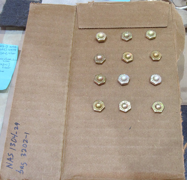 I want to prime the bolts that will be used in the wheel and brake assemblies. |
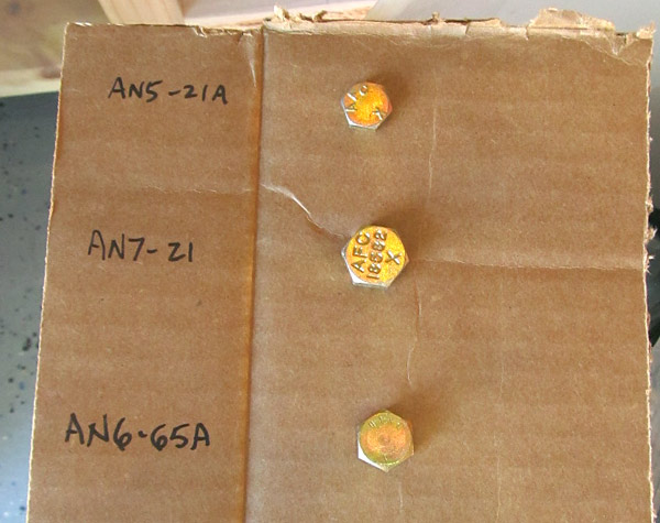 These are the bolts that are used in the following: (AN5-21A) bolt that is used to secure the (WD-1031)) axle flange to the (U-01406) nose gear leg, (AN7-21) bolt that is used to secure the (U-01416) nose gear link assembly to the (U-01406) nose gear leg, and the (AN6-65A) bolt that is used to secure the nose wheel and tire assembly and the (U-00024) nose wheel axle together. |
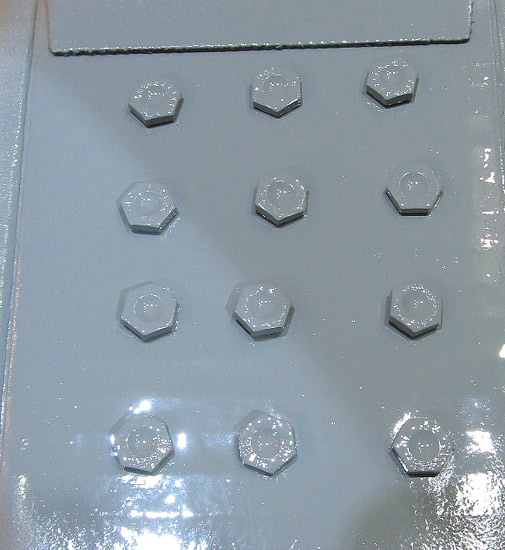 The bolts were primed with SPI (6610-4) gray primer. |
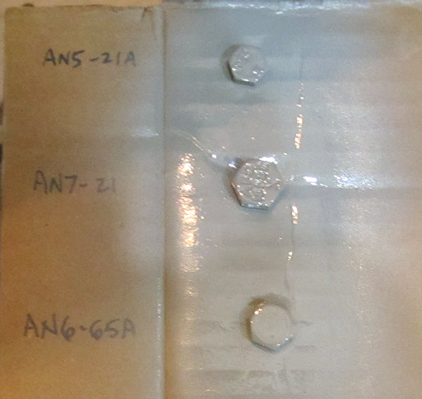 The bolts were primed with SPI (6610-4) gray primer. |
 This is the (U-00024) nose wheel axle. |
 The (U-00024) nose wheel axle was primed with SPI (6610-4) gray primer. |
 As per step 2, on page 40A-02, figure 1, I final torqued the (FF-01400) engine mount bolts to a final value of 184 inch/pounds. (170"/lbs. + 14"/lbs. drag = 184"/lbs. |
 Each bolt was final torqued and torque seal was applied. |
 Each bolt was final torqued and torque seal was applied. |
 Each bolt was final torqued and torque seal was applied. |
 The main gear axles (U-00009) and attachment bolts are being prepared for priming with epoxy primer. |
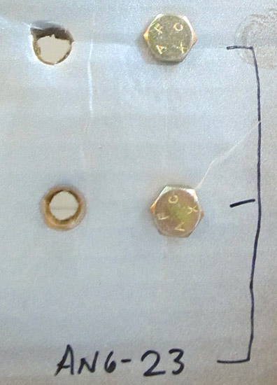 The (AN6-23) bolts shown here are going to be primed (just the heads); these bolts are used to attach the (U-01406) nose gear leg to the (FF-01400) engine mount. |
 I am priming the hardware to attach axles to the landing gear with SPI (6610-4) gray primer. |
 This is a (U-00009) main landing gear axle, it is primed with SPI (6610-4) gray primer. |
 The (U-00009) axles were primed with SPI (6610-4) gray primer. |
 The (U-00009) main landing gear axles, (MS21025-20) nuts, (MS21025-24) nuts, and (AN6-23) bolts were all top coated with UTECH 500 (S60385) Insignia White paint. |
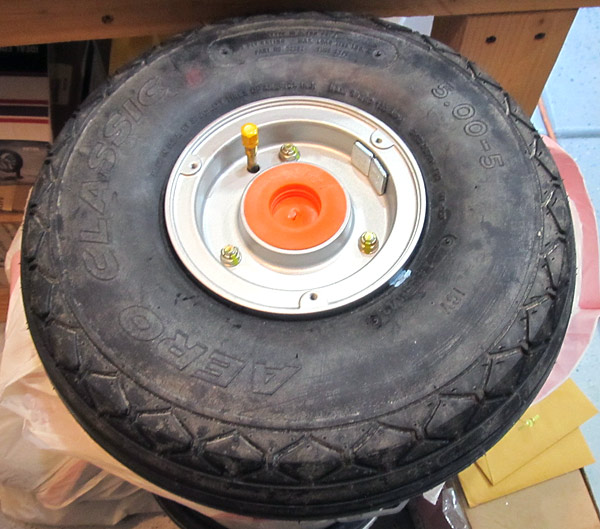
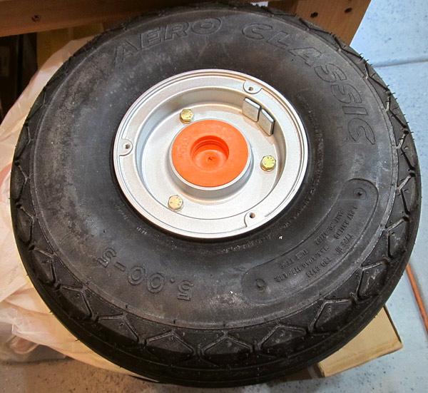
 It's time to mount the tires and tubes to the wheels. |
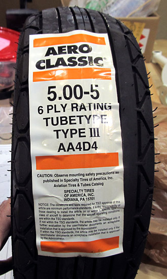
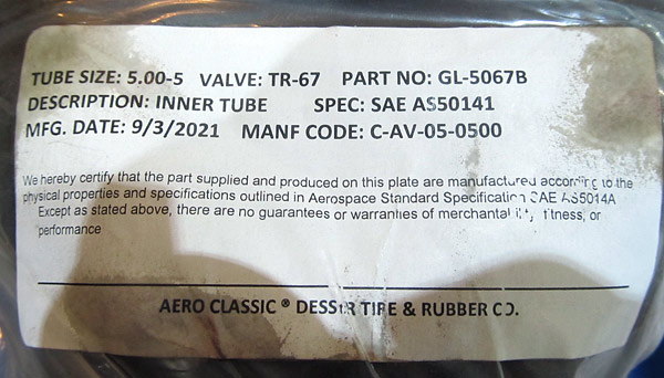
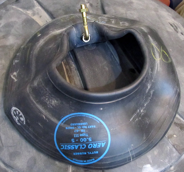
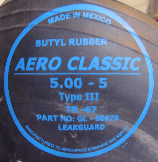
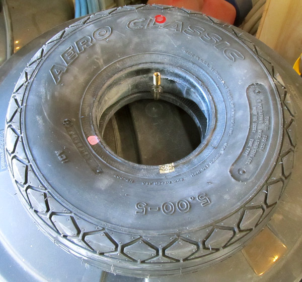
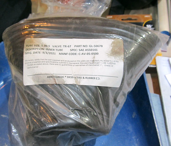 The inner tubes are Aero Classic "Leakguard" butyl rubber 5.00-5 (GL-5067B) inner tubes. |
|
|
|
|
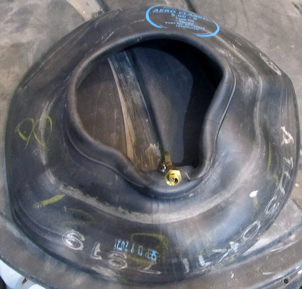
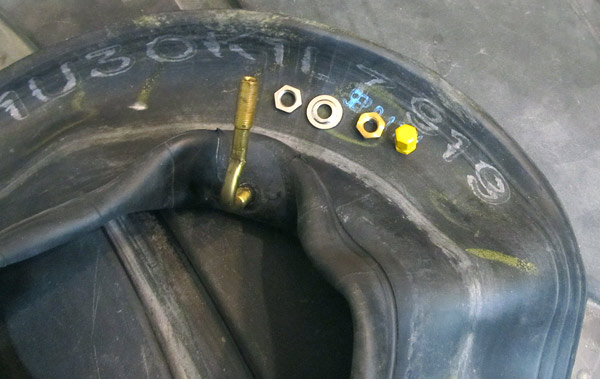 As per step 5, on page, 40A-02, figure 3, the nuts and washers were removed from the Aero Classic "Leakguard" inner tubes. |
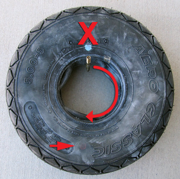
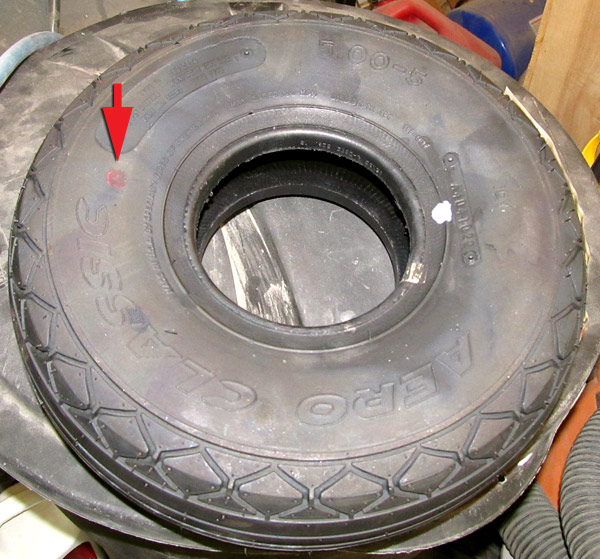 Make sure to locate the red dot on each of the tires so that when you mount the inner tubes the valve is located adjacent to this dot. |
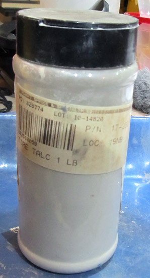 The inner tubes and also the inside of the tires should be "dusted" with tire talc. |
 I dust the inner tubes and also the inside of the tires and then "stuff" the inner tube into the tire. |
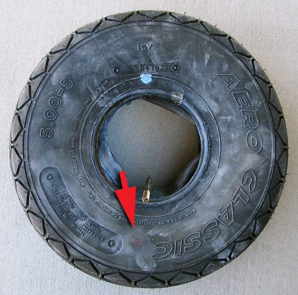 This is the correct position of the inner tube with the valve stem adjacent to the red dot... |
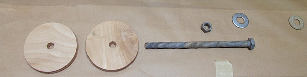 To help mount the wheel halves inside of the tire/inner tube I made a jig to hold the halves together while placing the bolts in place. The jig is just a couple pieces of plywood cut to the diameter of the flat spot of the center hub of the wheel and then using a long bolt with two washers clamp everything together to keep all in place. |
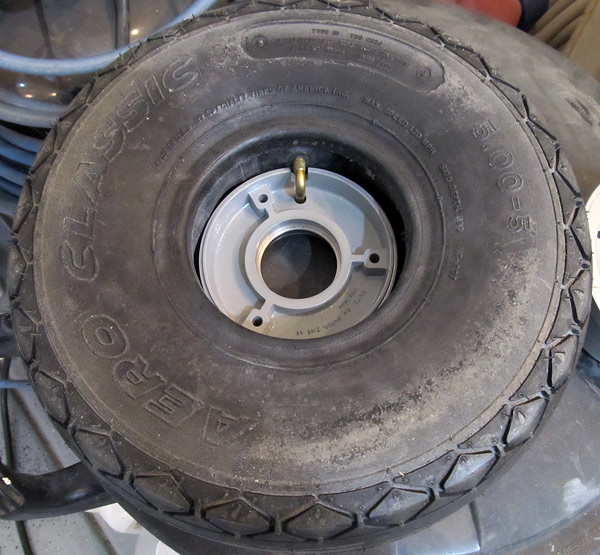 First, I put the front half of the wheel face down into the tire, making sure not to pinch the inner tube and also making sure that the valve passes through the valve stem hole. |
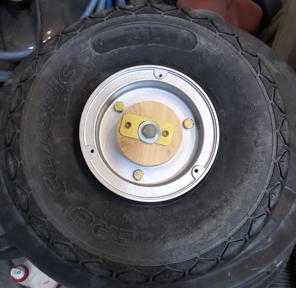
 The back half of the wheel was put in place, again making sure that the inner tube wasn't being pinched and that the bolt holes are aligned. |
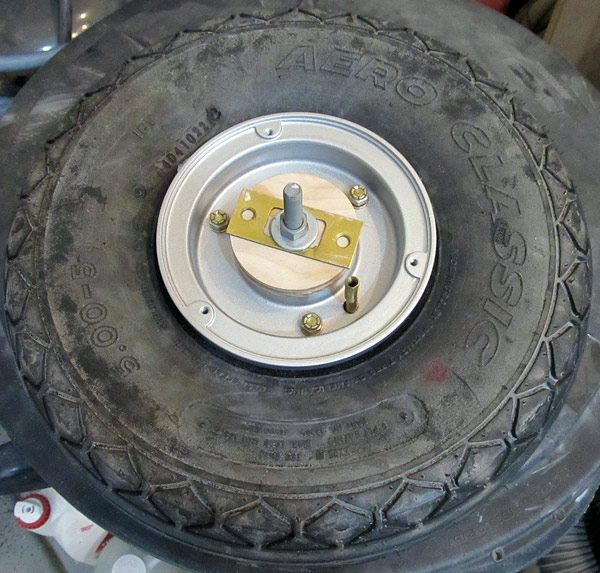 I installed my homemade jig to keep the wheel halves together and from wandering off center. The lock nuts of the wheel bolts were installed, tight, but not fully torqued yet. |
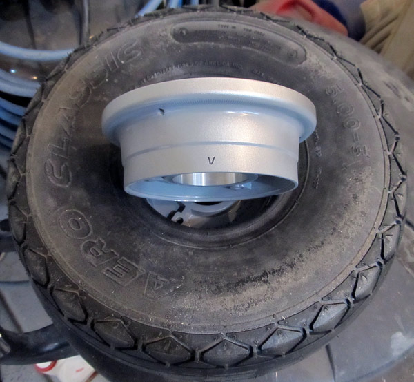
 Here is what it looks like from the back. |
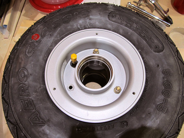
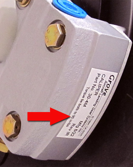
 When it looked like the tire was fully seated against the wheel halves, I torqued the lock nuts to the recommended torque which is 90 inch/pounds. |
 As per step 6, on page 40A-02, the inner tube was slowly inflated to 25 psi, then deflated, and reinflated several times to work out any possible wrinkles and then as per step 7, on page 40A-02, the tire was inflated to the recommended 35 psi with the valve stem core installed. |
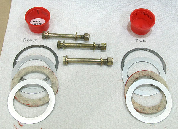
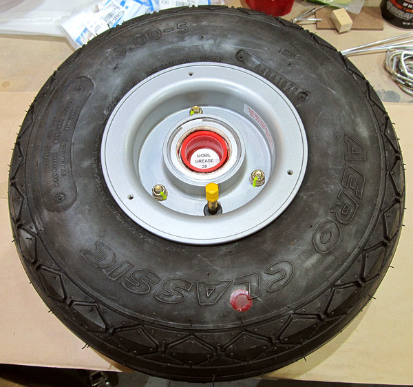
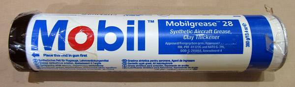 Grove mfg. recommends Mobilgrease 28 to repack their wheel bearings so I used it on all of the wheel bearings. |
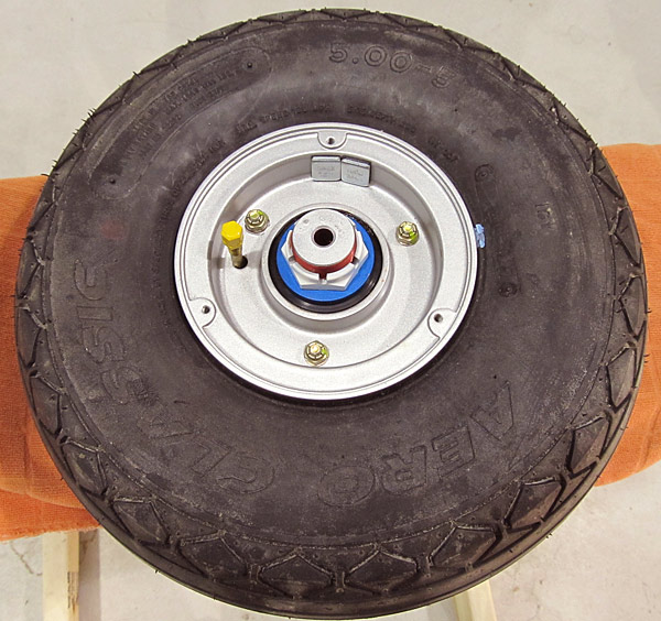
 The wheel bearings were cleaned earlier with mineral spirits and dried with compressed air. Now the nose wheel bearing will be repacked with Mobilgrease 28. |
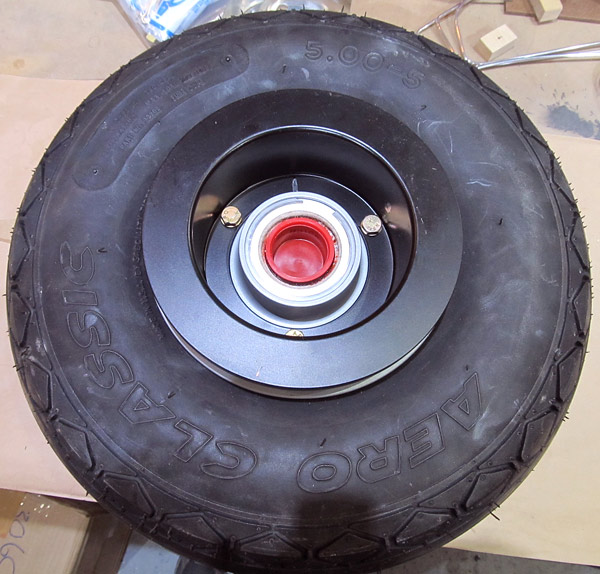
 The nose wheel bearings were reinstalled onto the nose wheel rims. |
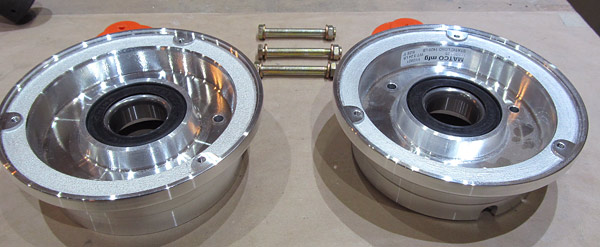
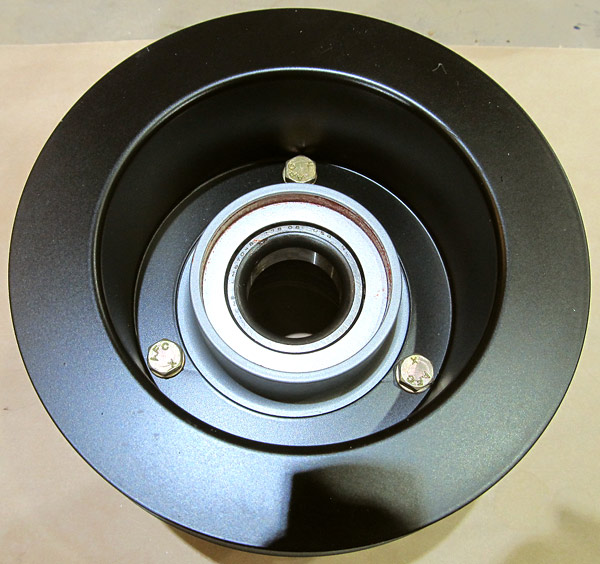
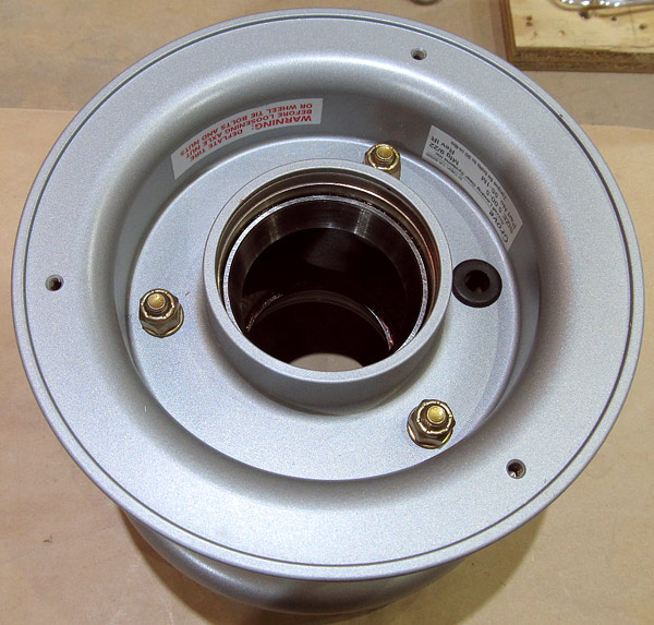
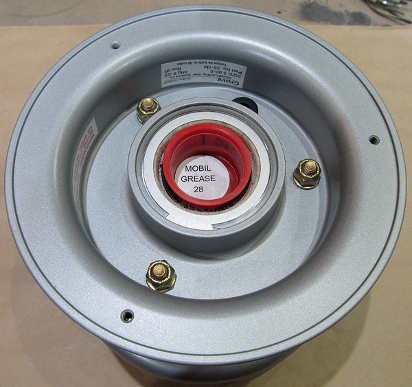 The Grove (55-1M) wheels are next to be disassembled in order to mount the inner tubes and tires. |
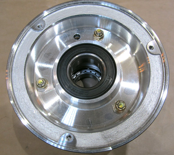
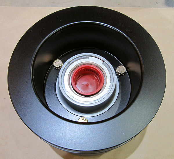 This is the back of the Grove (55-1M) wheel. The black section is the brake disc. |
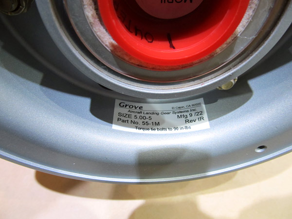 This is the Grove manufacturer's tag. |
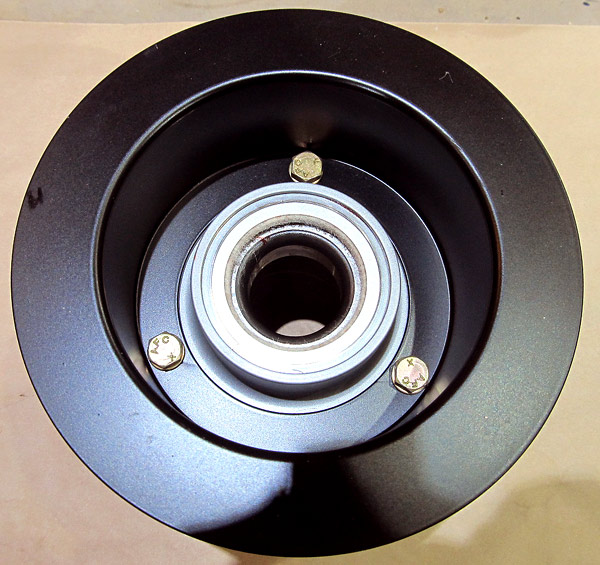
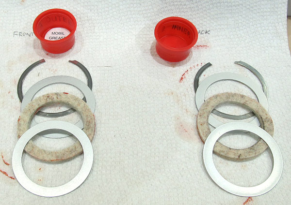
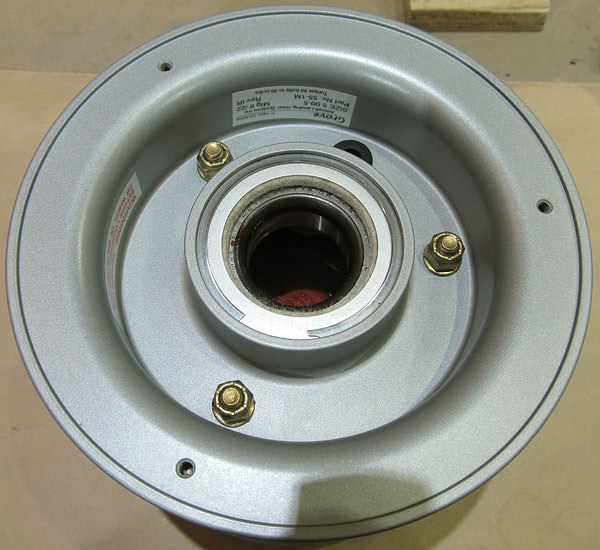 As per step 1, on page 40A-03, figure 2, the wheel bearings were pulled from the wheels paying attention to the order of dismantling so that they can be reassembled in the correct order. |
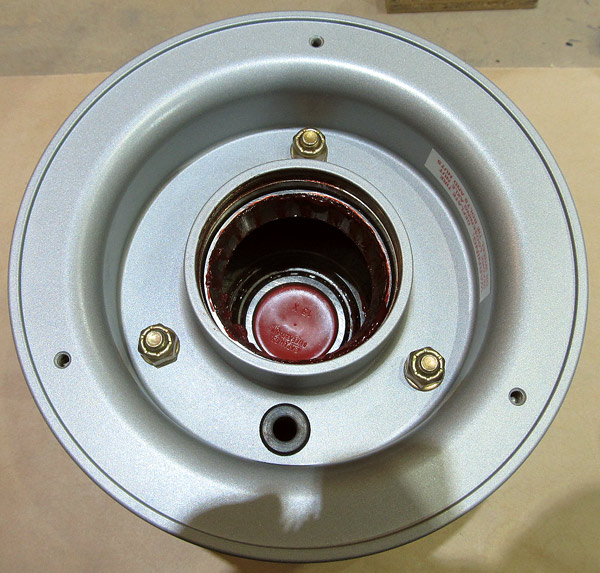
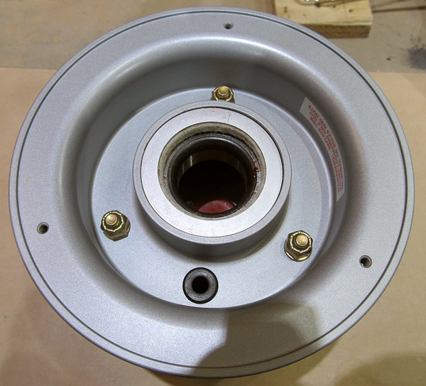 The part to come off next is a large flat washer. |
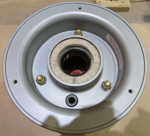 The felt grease seal comes off next. |
 The second large washer comes off next. |
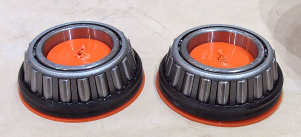
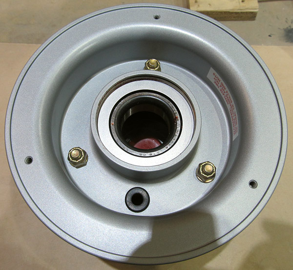
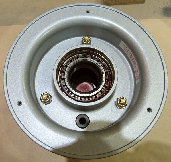 Finally we get to the actual wheel bearing, it gets pulled and then cleaned. |
 The wheel bearing removed, (on one side), there are two per wheel. |
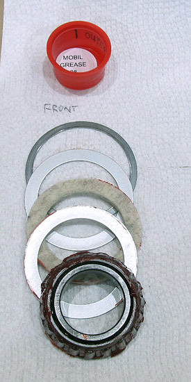 This is what I was saying earlier, it's how I disassemble the parts in order, (top to bottom), flipped over (face down), and placed in descending order of disassembly. |
 I wiped off the old grease from the rim where the wheel bearing was. |
 I cleaned the wheel bearing with mineral spirits and then dried it with compressed air. |
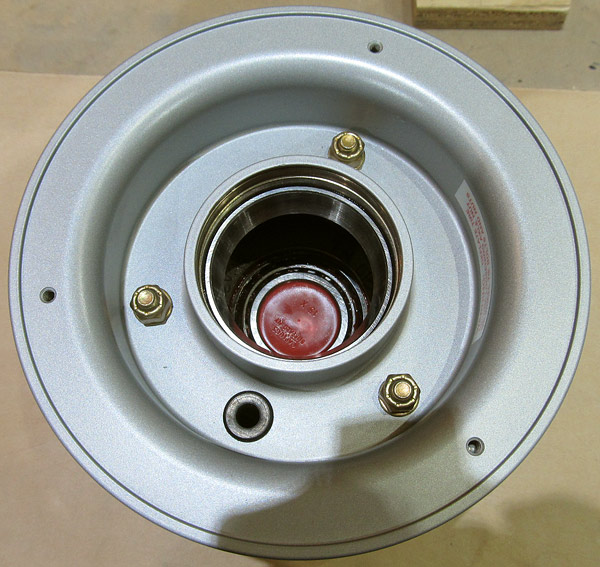
 Now on to the back side of the wheel and remove the second wheel bearings and parts. |
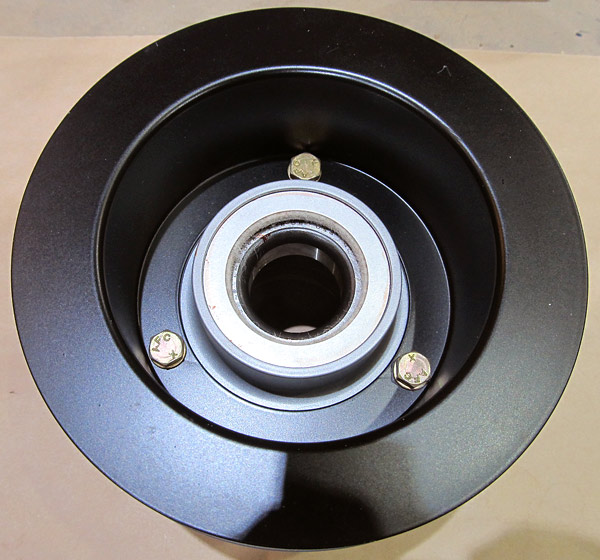 The large flat washer is the next to come off. |
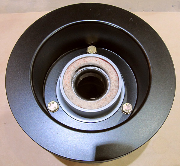 The grease seal felt comes off next. |
 The second large flat washer comes off next. The wheel bearing will be pulled out after the washer. |
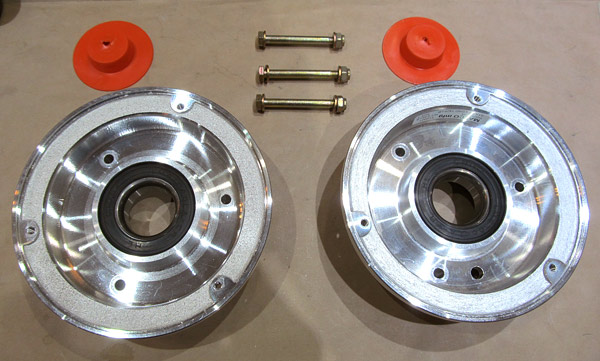
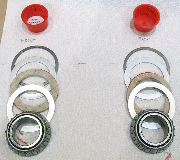 Here are the front and back wheel bearing assemblies lined up in order so that they can be reassembled later. |
 I wiped out all of the old grease from the wheel rim where the wheel bearing was. |
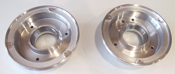
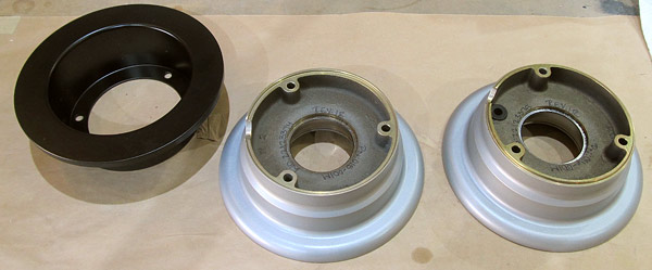
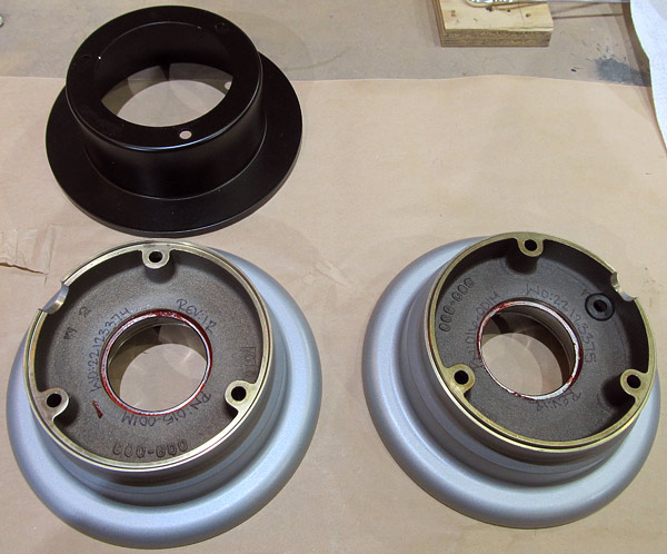 Here the wheel halves have been separated. |
 The wheel bearing parts and the wheel through bolts. |
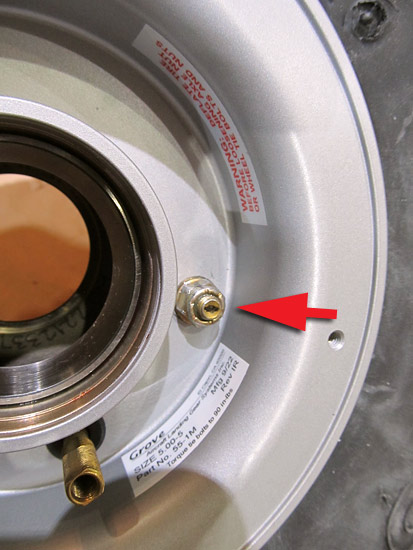
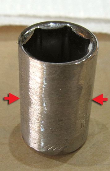 As I said before, the tolerances for the bolt heads on the back of the wheel half is very close. In order to be able to use a socket to loosen and take apart the wheel halves I had to grind the sides of a 7/16" socket so that I could "clear" the side walls of the brake disc. |
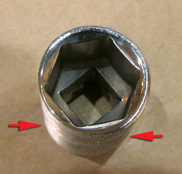 Here's what the socket looks like from the end. |
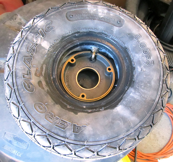 As per step 3, on page 40A-03, the Aero Classic inner tube was "dusted" with tire talc as well as the inside of the Aero Classic tire. |
 Just like when the nose wheel tire was mounted, the back wheel half and the brake disc was placed onto the front rim half and using the jig, (described earlier), to hold everything in place, the tire through bolts were installed. |
 As per step, 5 and 6, on page 40A-03, the tire was inflated to the recommended 40 psi, the valve stem core was installed and inspected for leaks and the tire was inspected for leaks and proper seating around the rim. |
 As per step 3, on page 40A-03, the Aero Classic inner tube of the remaining main gear tire was "dusted" with tire talc as well as the inside of the Aero Classic tire making sure to align the valve stem of the inner tube with the red dot on the tire. |
 Back to the previous tire, time to repack the wheel bearings with grease and install them.... |
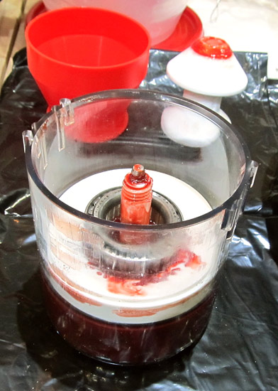 This is the tool that I use to repack wheel bearings, you saw it before when repacking the nose wheel bearing.... |
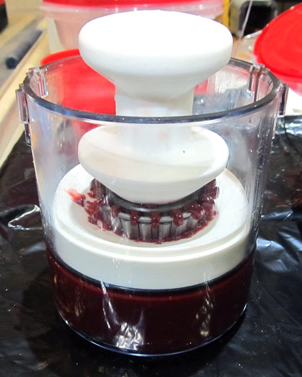 Just place the wheel bearing, cone side down, into the tool and press hard until the grease forces its way up through the bearings.....easy peasy! |
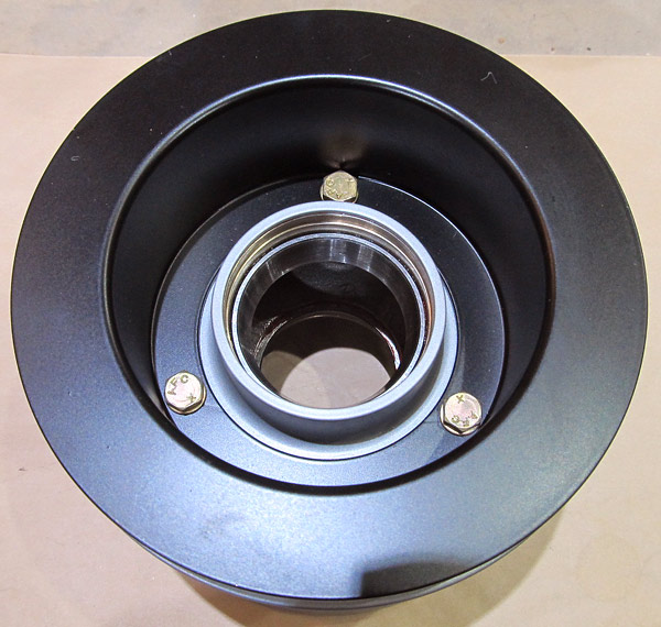
 The bearings were repacked and reinstalled onto the front side of the Grove wheel hub just as described earlier and as per step 8, on page 40A-03. |
 The bearings were repacked and installed onto the back side of the Grove wheel hub as described earlier and as per step 8, on page 40A-03. |
 The second Grove wheel assembly was disassembled just like described on the previous wheel but this time I ran into a problem....good news though everything eventually worked out fine. |
 The bearings and all of the parts were removed just like before. |
 The old grease was cleaned out of the hub centers. |
 The wheel halves were disassembled. |
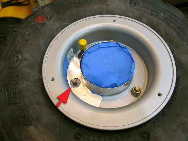
 The wheel halves were re-assembled just like before but this time when I tightened the through bolts this one would not tighten, no way no how! |
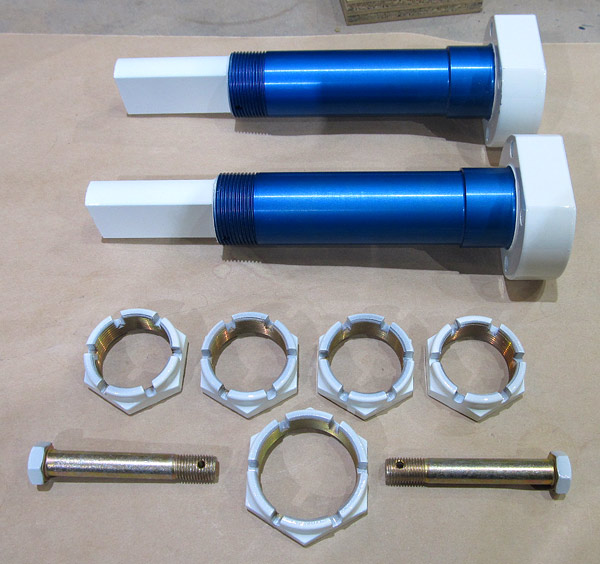
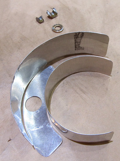 The finish on the Grove rims is really nice so in order to remove the lock nut, which I suspect is stripped, I made these aluminum protector plates to protect the paint and rim metal. |
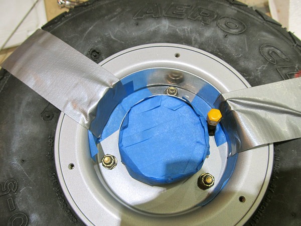 I held the protector plates in place with blue tape and good old duck tape! |
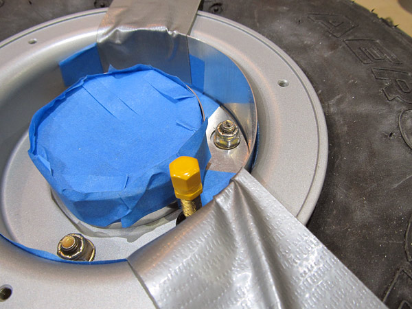 I mostly used a hack saw to cut through the sides of the (AN365-428A) lock nut. |
 The cut gets deeper, it's a tough nut to crack haha! |
 Still working on the removal of a stripped nut and bolt. I mentioned it before, this is a (AN4-23A) through bolt. I am cutting 180° opposite the first cut as well to get a clean split of the nut off of the bolt. |
 Finally after about 10 hours of work I got the lock nut removed. It took longer than I thought it would but it was tight quarters to work in and I didn't want to do anything extreme to get the nut off. |
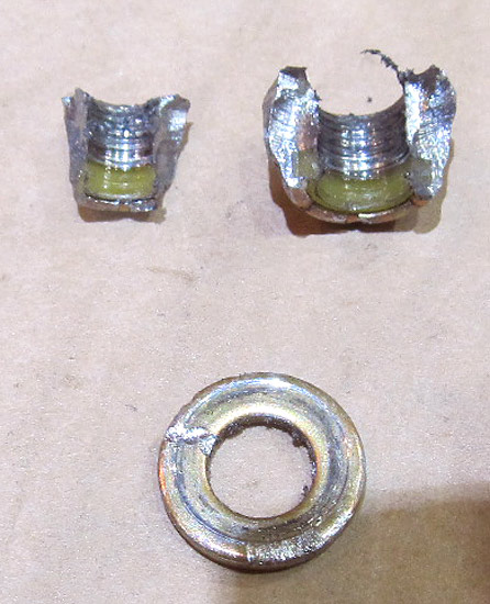 This is the (AN365-428A) lock nut that was removed. |
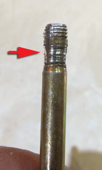
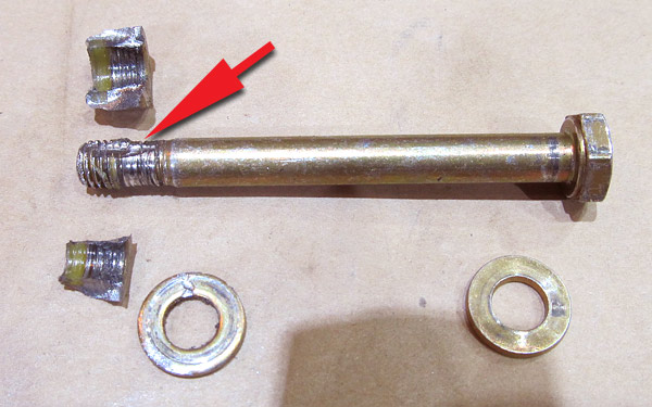 This is the (AN4-23A) through bolt that was removed, it's pretty evident where the bolt was stripped. This bolt didn't even make it to final torquing, the nut just spun around without very much wrench pressure. |
|
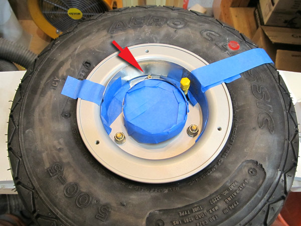
 I cleaned the area around where the bolt was very thorughly before removing the bolt, don't want to get any dust down inside of the tire! |
 Replaced the (AN4-23A) bolt, (AN960-416) washers, and (AN356-428A) lock nut on the Grove wheel. |
 As per step 6, on page 40A-03, checked the valve stem for any leaks and the tire for proper seating. |
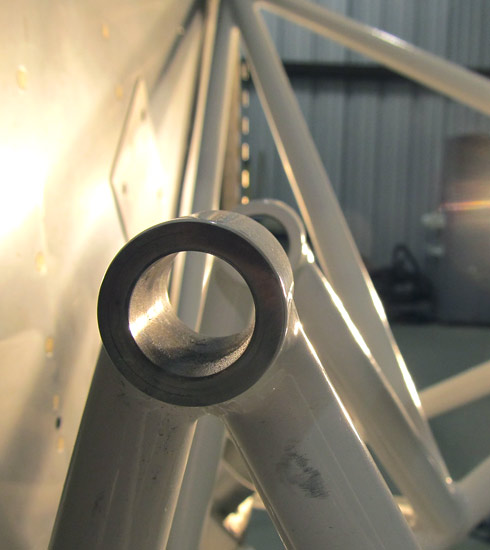
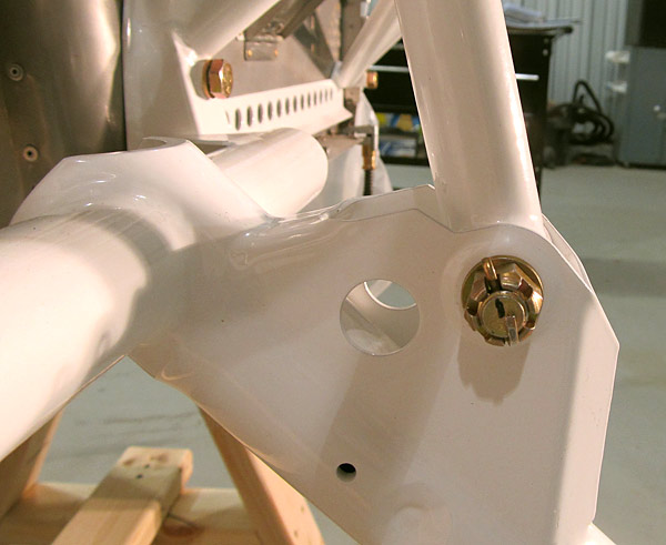
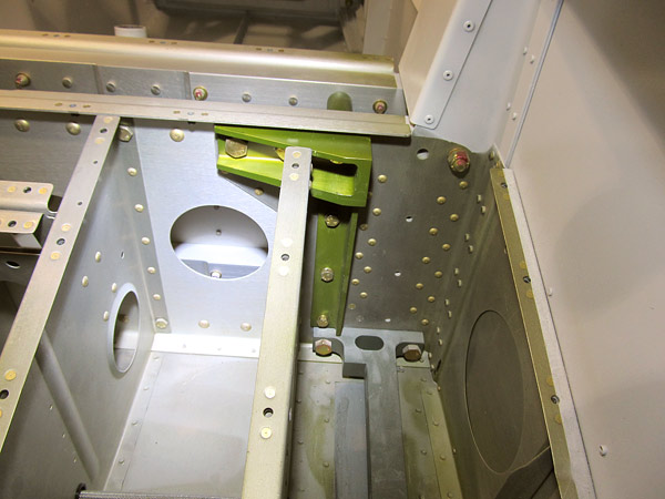 As per step 9, on page 40A-03, figure 3, installed the (U-01404-L and U-01404-R) left and right upper gear braces and the (BUSHING-AL.377x.75x1.6875) aluminum bushings using the hardware called out in figure three to the Center Section Assembly. |
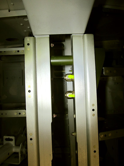 This is the (BUSHING-AL.377x.75x1.6875) aluminum bushing on the right side of the fuselage. |
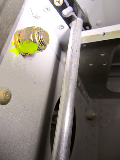
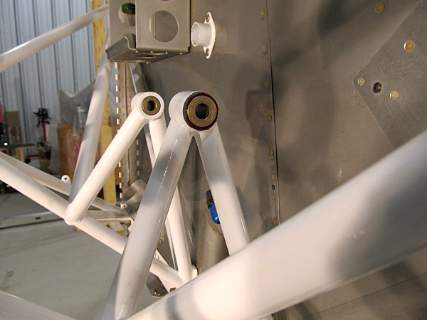
 This is the (U-01404-L) left upper gear brace, the (AN3 and AN6) bolts that connect this to the Center Section Assembly can clearly be seen. |
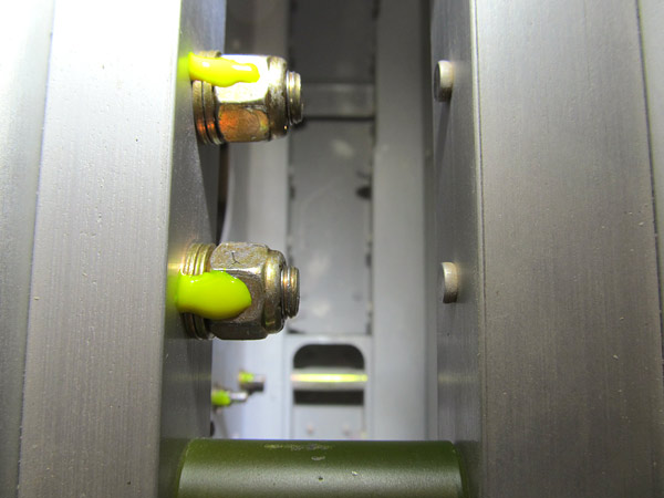 The (AN6) bolts were torqued to 184 inch/pounds and torque sealed. The (AN3-6A) bolts were torqued to 42 inch/pounds and torque sealed. |
 (AN365-624A) lock nuts attached to the (AN6) bolts. |
 (AN365-624A) lock nuts attached to the (AN6) bolts. |
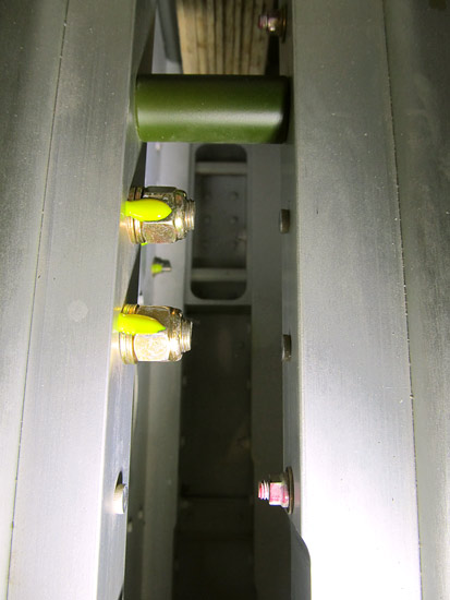 (AN365-624A) lock nuts attached to the (AN6) bolts. |
 This section of the builder's manual, (Section 40) has been a challenge for me. |
 UP FRONT WARNING: |
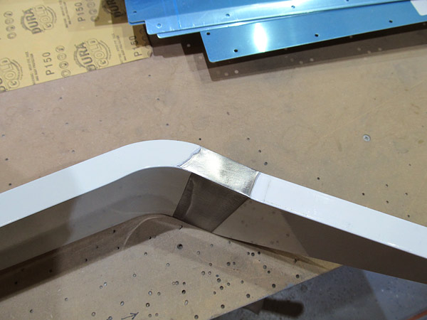
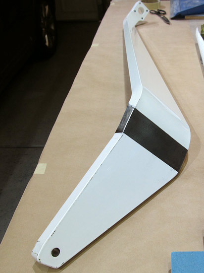
 I used some shims at the bottom of the gear leg to help hold it up in an approximate final position as I marked out trim lines for filing the gear leg to fit into the "notch" of the (U-01402) lower gear brace. I used a fine tip sharpie to mark out my trim lines. |
 I used a heavy file to file the sides of the ()-01401-L and U-01401-R) left and right main landing gear legs. The metal is dense and quite hard so a light file is not going to remove much material. I avoided using a grinder because I didn't want to build up much heat in the grinding process. |
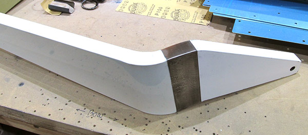
 This is the (U-01401-L) left main landing gear leg. I didn't just file on one side of the gear leg, I removed excess material on the forward and aft gear leg sides so that there was a symmetrical close fit. |
 This is what it looks like, I'm still not done with the fit as it will take a few more "fits" before the gear would rest in the "notch" of the (U-01402) lower gear brace. |
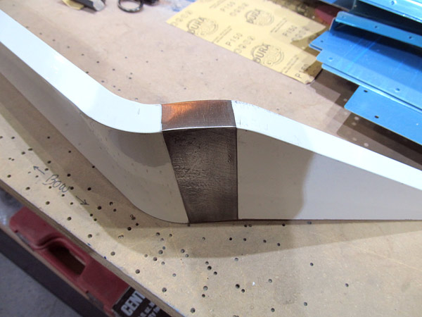
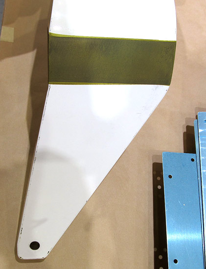
 You can see the dark spot in the side of the gear leg it's a low spot and the shiny exposed metal has to be filed down even more to meet that spot. If you look closely there is a slight "crown" in the edge here and it has to be flat before a nice fit is achieved. |
 Here you can see that the metal has been filed down to the low spot on the edge of the left main landing gear so that it is flat. |
 This is the opposite edge of the (U-01401-L) left main gear leg. It is almost where it needs to be but still needs some filing so that edge doesn't have as much of a "crown" on it and is flatter. |
|
|
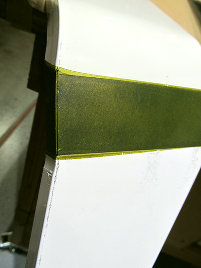
 I guess it goes without saying that all of the filed areas need to be primed before being installed. |
 I primed the bare metal part of the landing gear with Tempo (A-702) green self etching zinc phosphate primer. |
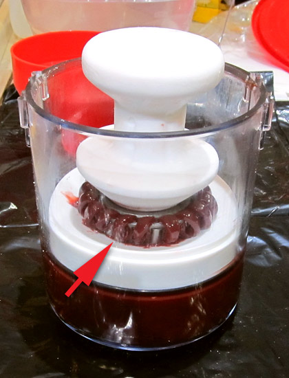
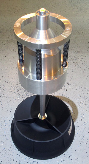 As a side project I wanted to balance the wheels for our airplane. I started off thinking that this wheel balancer would work, but it didn't. First the top is too wide for aircraft wheels, the diameter of the center of our aircraft wheel would not allow it to sit on top of the balance unit, and even after I made an adapter to allow it to sit atop the unit everything was too top heavy and it just didn't work! |
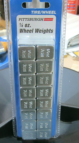 These are the wheel weights that I will use to balance the wheel. |
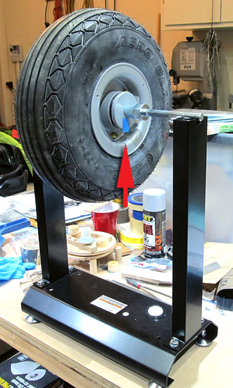 My next option was to use a motorcycle wheel balancer so I exchanged the previous balancer for this one. In case you haven't guessed by now, these are both from Harbor Freight. |
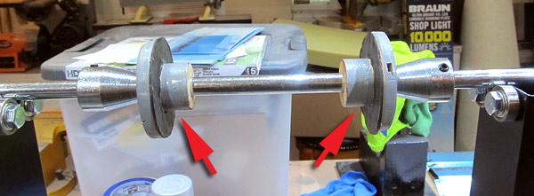 This is what the adapters look like, they are made out of wood and are lined with inner tube so there is a snug fit. |
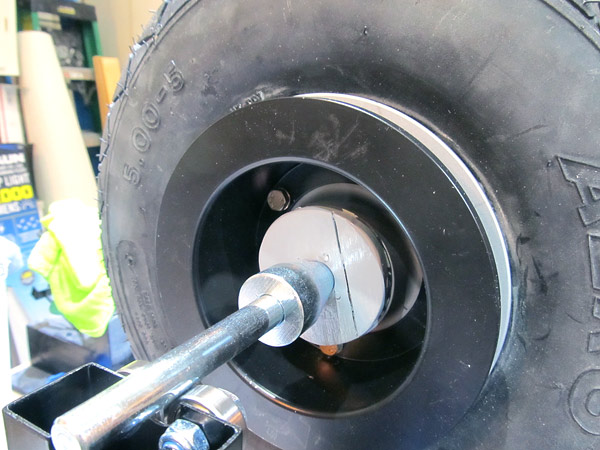 The conical spindle snugs up against the adapter in the center of the adapter and the wheel can be balanced with the bearings in place. |
 The wheel will naturally come to rest with the heaviest side of the tire and wheel at the bottom. I put a piece of blue tape to mark the heavy spot and start placing balancing 1/4 ounce weights opposite the blue tape point. |
 The weights are temporarily held in place with blue tape as well and when you displace the wheel it should remain in place staying motionless. If it doesn't stay in place that means you have to either add more weight or change the location of the balancing weight.....it's pretty easy! |
 The #1 main gear wheel needed 1/2 ounce weight for balancing. |
 The #2 main gear wheel also needed 1/2 ounce weight for balancing. |
 The nose wheel needed 1 ounce weight for balancing. I put 1/2 ounce weight on the front. |
 I put 1/2 ounce weight on the back of the nose wheel to complete the balancing. |
 Back to the frustrating task of fitting the (U-01401-L and U-01401-R) left and right main gear legs to the fuselage. It took two more sessions of installing, checking the fit, marking trim lines, uninstalling and refiling before I was able to get a nice close fit. |
 Well, looks like it's really going to happen this time! |
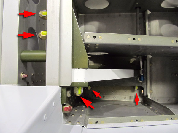
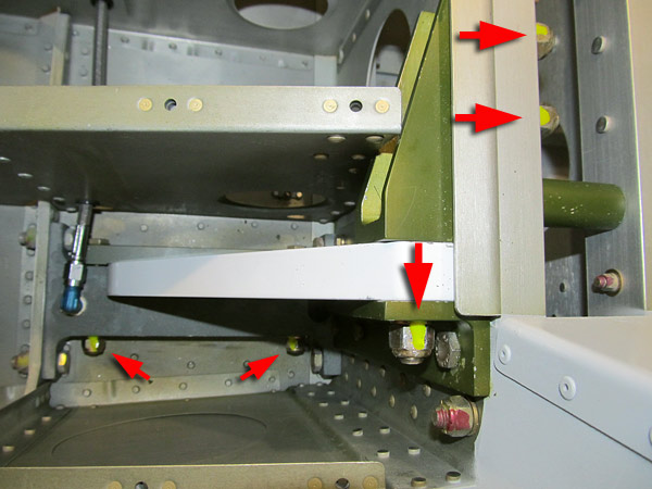 As per step 4, on page 40A-04, figure 3, push the (NAS1306-22) bolt at the top of the (U-01401-L and U-01401-R) main gear legs, through the (U-01405-L and U-01405-R) gear attachment angles and install the called out washers and nuts in figure 3. |
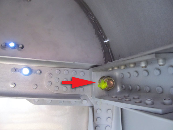
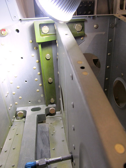
 This is the (NAS1305-19) bolt at the top of the (U-01405-R) right gear attachment angle that had to be bolted in first to the aft center section bulkhead assembly. |
 This is the left side of the fuselage, everything went together just like the right side did. |
 As per step 2, on page 40A-04, the (U-01401-L and U-01401-R) main landing gear legs were slid through the bottom slots of the fuselage upward and aligning the top hole of the gear legs with the hole in the (U-01404-L and U-01404-R) upper gear braces per figure 4. The (NAS1306-22) bolt was slid, as depicted in figure 3, through the upper gear braces only far enough to hold everything in place. |
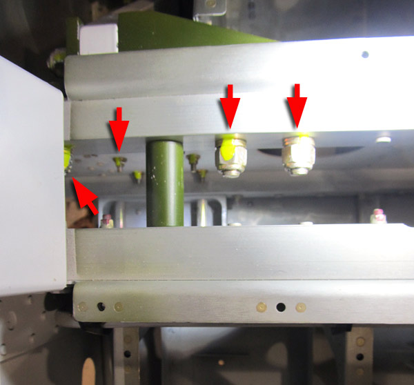
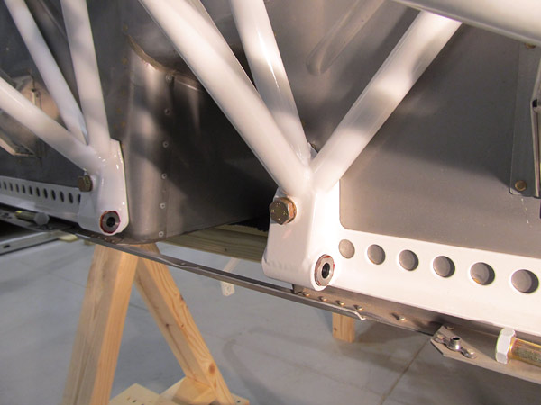
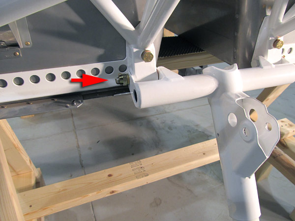
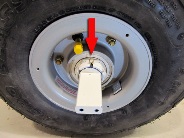
 The space to get at the nuts attaching the (U-01403) gear attachment bar, (U-01401) main landing gear leg, and the (U-01402) lower gear brace together is tight. It helps to use a crow's foot attachment when final torquing the (AN365-524) lock nut. |
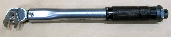 To have a valid torque make sure that the crow's foot is 90° to the handle. |
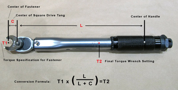 To have a valid torque when the crow's foot isn't 90° to the handle use the formula: T1 x (L/L + C) = T2 |
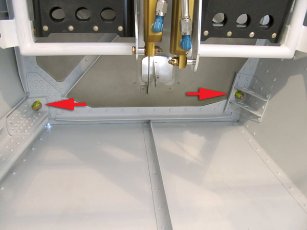
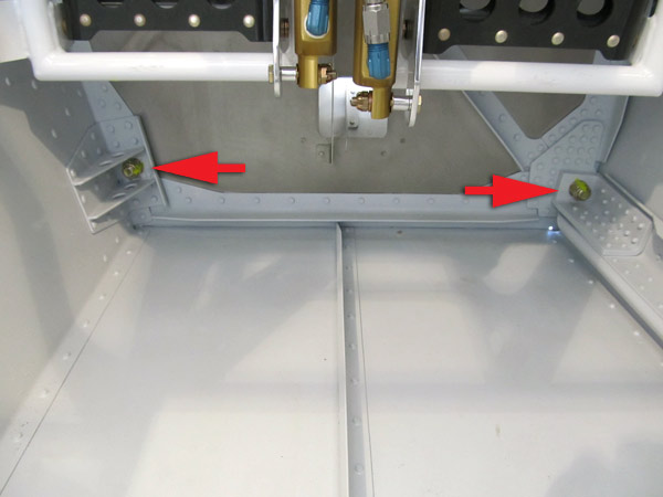
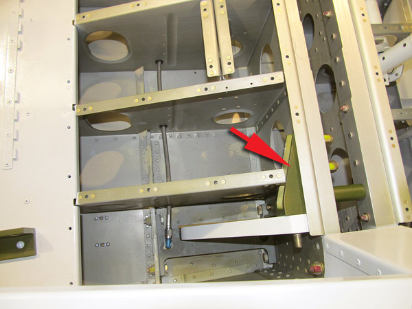
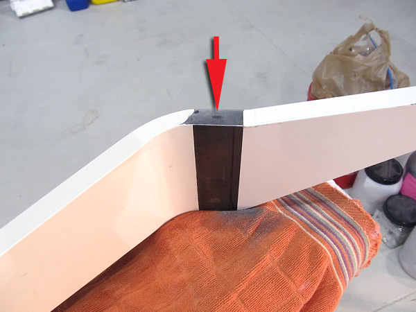
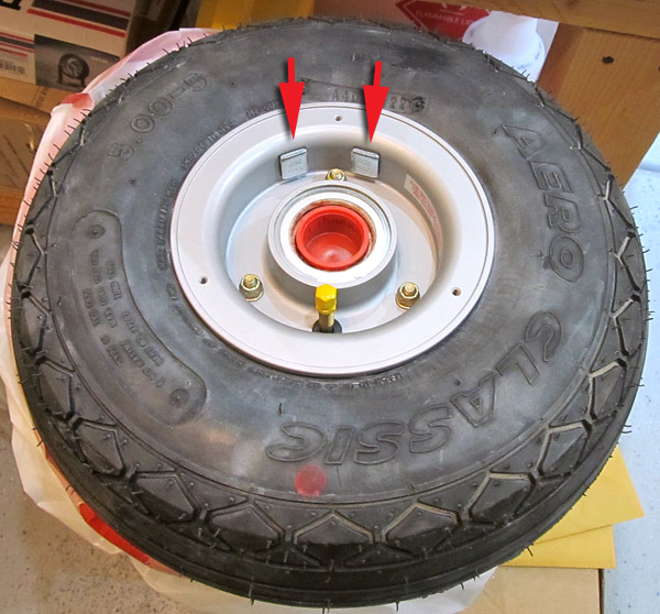
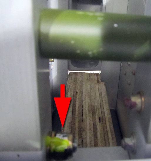
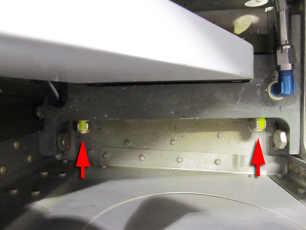
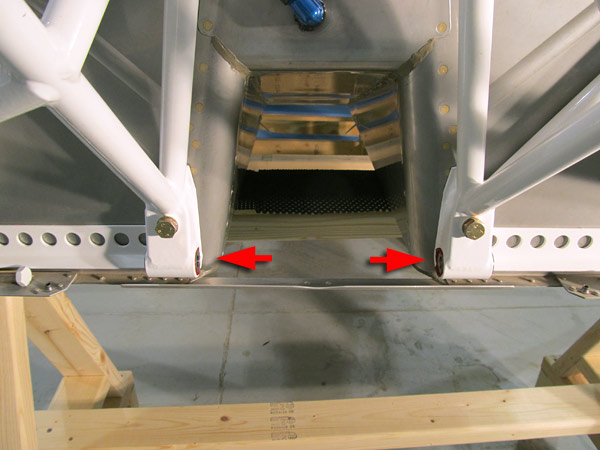
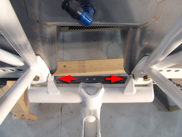
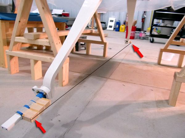
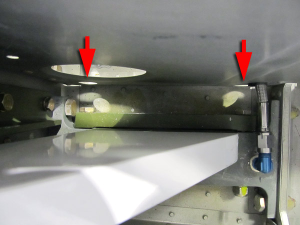 The red arrows in this photograph point to the access holes in the (F-01416-L and F-01416-R) seat ribs that are used to install the (NAS1305-36) bolts holding the (U-01403) gear attachment bar, (U-01401) main gear leg, and (U-01402) lower gear brace in place. |
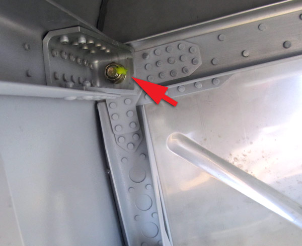
 This is the (NAS1305-19) bolt at the top of the (U-01405-L) left gear attachment angle that had to be bolted in first to the aft center section bulkhead assembly. |
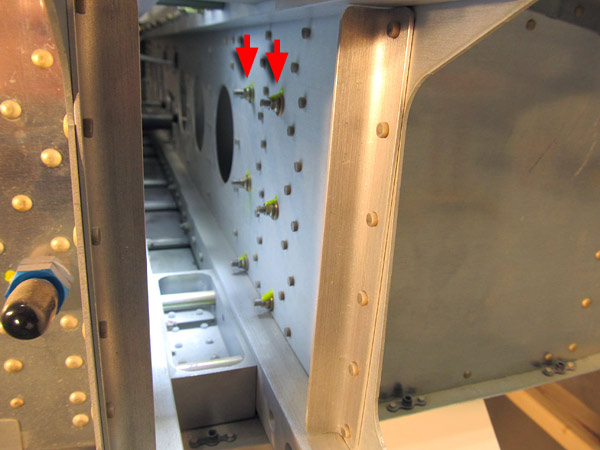
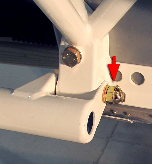
 I final torqued the remaining bolts that attach the (U-01405-L and U-01405-R) gear attachment angles to the (F-01404) aft center section bulkhead assembly. The bolts and hardware are: (AN3-6A) bolts, (NAS1149F0363P) washers, and (MS21042-3) metal lock nuts. |
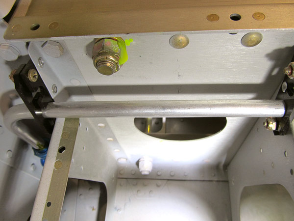
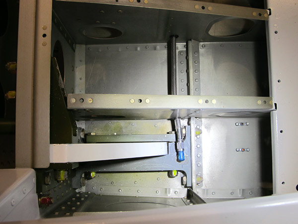
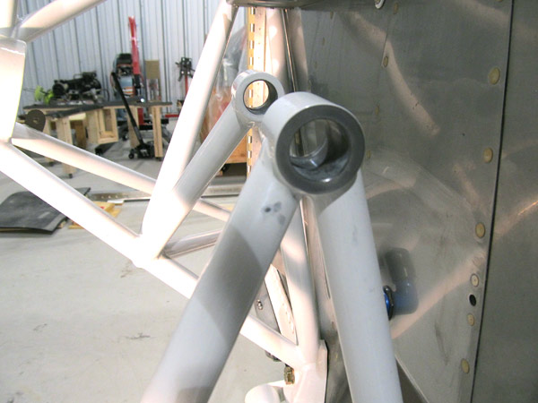
 This is the right landing gear (U-01401-R) installed. This is an overhead view. |
 This is an overhead picture of the (U-01403) gear attachment bar and the (U-01401-R) main landing gear leg. |
|
The (U-01403) gear attachment bars are not flat on each side, the side that is up against the main landing gear leg is curved in the center, the purpose of this "high point" in the curve is to provide a built in wear surface. Because the curved portion rests up against the (U-01401) main landing gear leg there will be a gap. |
 All of the bolts on the right (U-01405-R) gear attachment angle have been final torqued and torque sealed. |
 This is an overhead view of the left landing gear attachments. |
 The bolts have been final torqued and torque sealed. |
 This is the hardware called out for attaching the (U-01406) nose gear leg to the (FF-01400) engine mount. |
 As per step 1, on page 40A-05, figure 1, some remaining powder coat on the indicated sections of the (U-01406) nose gear leg was removed. |
 The (AN6-23) bolts will attach from the inside of the (FF-01400) engine mount. |
 As per step 3, on page 40A-05, figure 1, the (U-01406) nose gear leg was bolted onto the (FF-01400) engine mount using the hardware called out in figure 1. |
 The (AN310-6) castellated nuts were secured with (MS24665-283) cotter pins. |
|
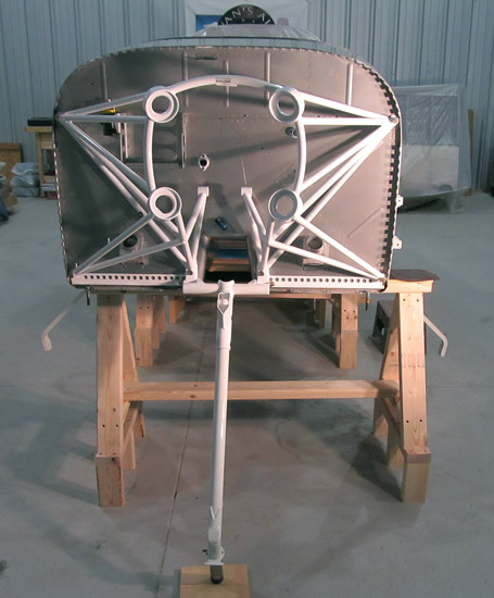
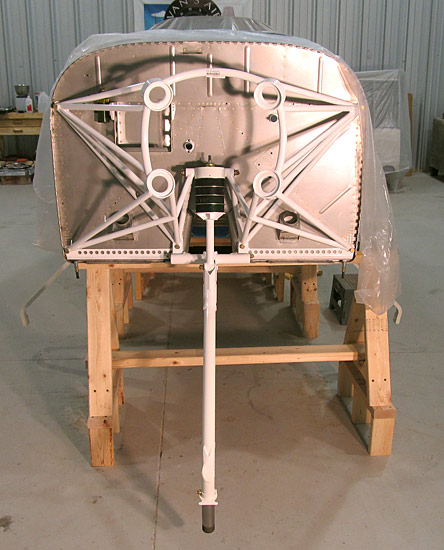
 The three landing gears are attached! |
|
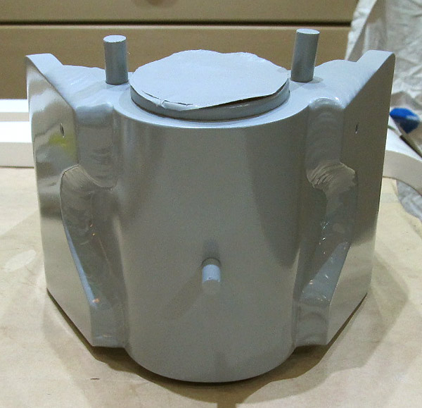
 As per step 1, on page 40A-06, figure 2 call out, removed excess powder coat from ends of the (FF-01400) engine mount bushing areas and the chamfered insides as well in order to allow the (U-01407) elastomer pad to swivel freely. |
 Removed excess powder coat. |
 As per step 2, on page 40A-06, figure 1, coated the outer surfaces of the (BUSH-F-ST.438x.750x1.328) flanged bearings with Mobilgrease 28 wheel bearing grease. |
 Inserted the (BUSH-F-ST.438x.750x1.328) flanged bushings into the (FF01400) engine mount. |
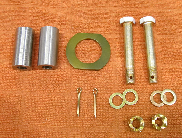
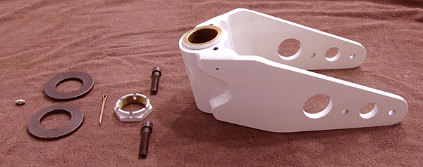
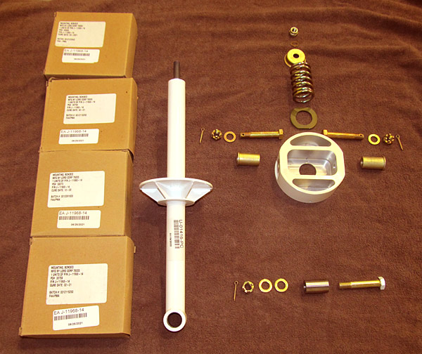 These are the parts needed to install the (U-01416) nose gear link assembly onto the (U-01406) nose gear leg and the (FF-01400) engine mount. |
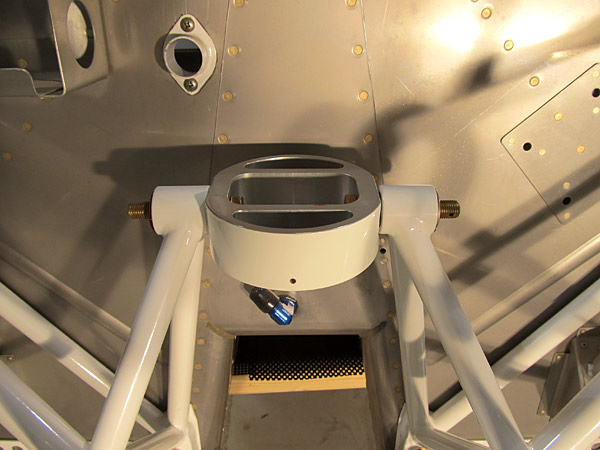 As per step 3, on page 40A-06, figure 1, I placed the (U-01407) elastomer pad in position on the (FF-01400) engine mount and inserted the called out hardware (AN7-22) bolts through the holes in the pad and into position through the flanged bushings on the (FF-01400) engine mount. |
 Overhead view of the (U-01407) elastomer pad in position on the (FF-01400) engine mount. |
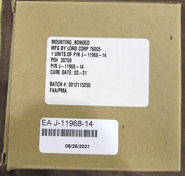 There are four (J-11968-14) nose gear elastomers that need to be placed onto the (U-01416) nose gear link assembly. |
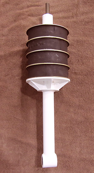 As per step 4, on page 40A-06, figure 1, I slid four (J-11968-14) nose gear elastomers onto the shaft of the (U-01416) nose gear link assembly. |
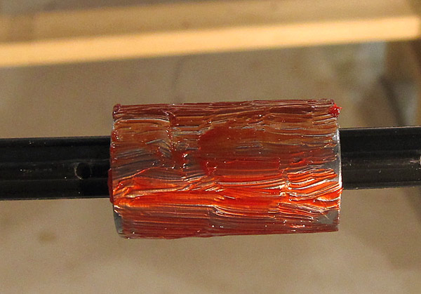 As per step 5, on page 40A-06, figure 1, I coated the (BUSHING-ST.438x.750x1.25) withMobilgrease 28 wheel bearing grease. |
 The (BUSHING-ST.438x.750x1.25) bushings were inserted into the lower end of the (U-01416) nose gear link assembly. |
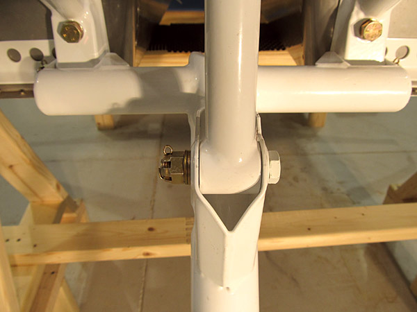
 As per step 6, on page 40A-06, figure 1, bolted the (U-01416) nose gear link assembly to the (U-01406) nose gear leg using the hardware called out. |
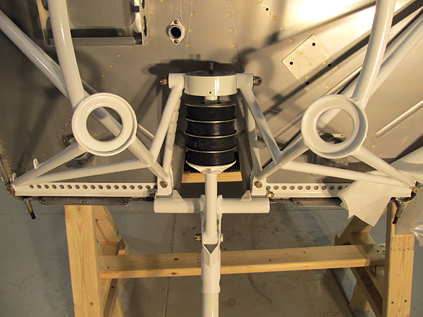
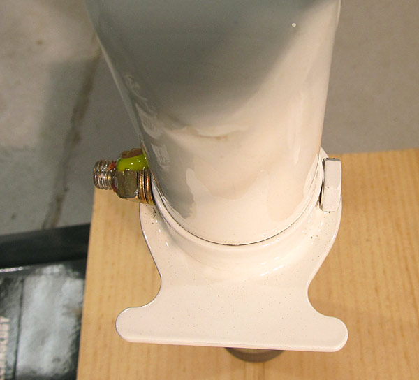
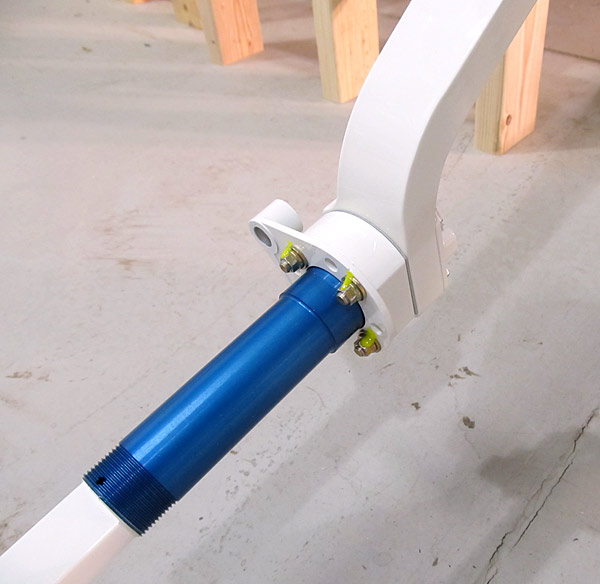
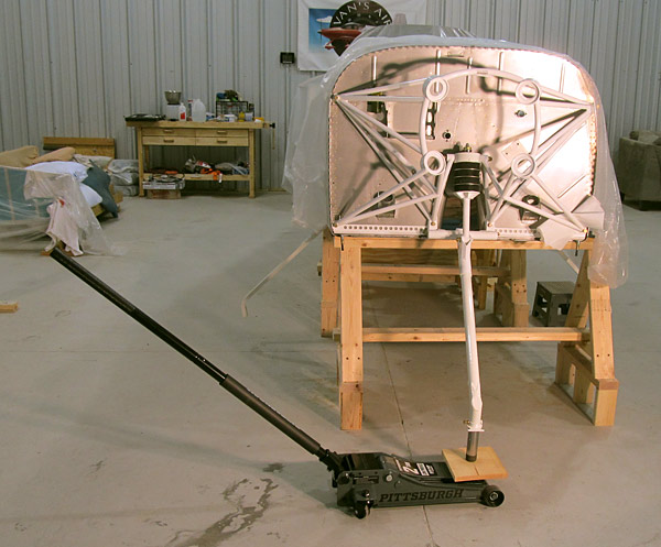 In order to install the (U-1002) isolator washer, (SPRING-0003) compression spring, (U-01420) link assembly cap, (NAS1149F0632P) washer, and to be able to thread the (MS21045-6) 3/8" lock nut into place, on top of the (U-01416) nose gear link assembly and the (U-01407) elastomer pad, I had to use our shop jack to lift the assembly enough vertically to compress the elastomers and compression spring. |
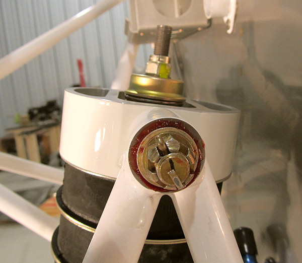 The (MS21045-6) 3/8" lock nut was final torqued to 184 inch/pounds (170"/lbs. + 14 "/lbs. drag = 184"/lbs). The nut was torque sealed. |
 The rest of the hardware called out was torqued and cotter pins were installed. |
|
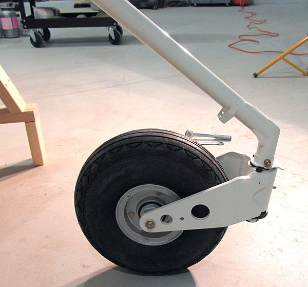
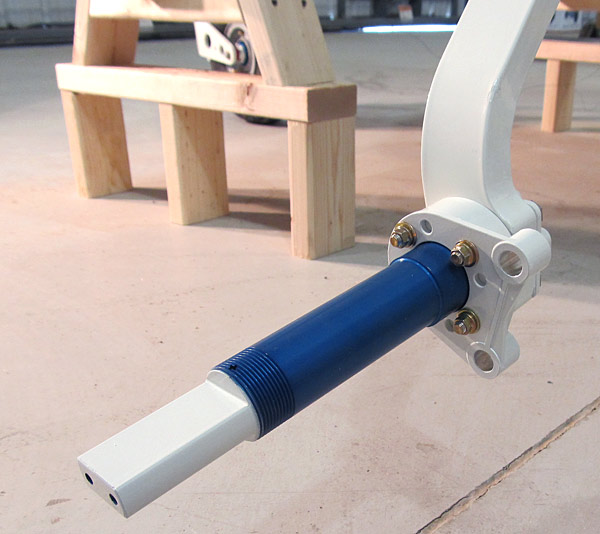
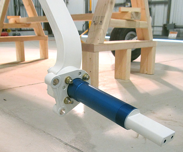
 Nose Gear Link Assembly Installed! |
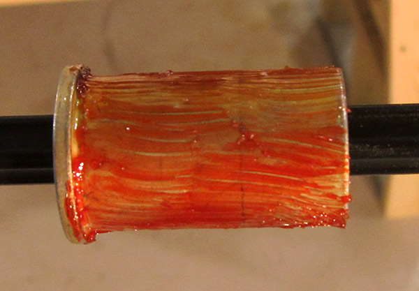
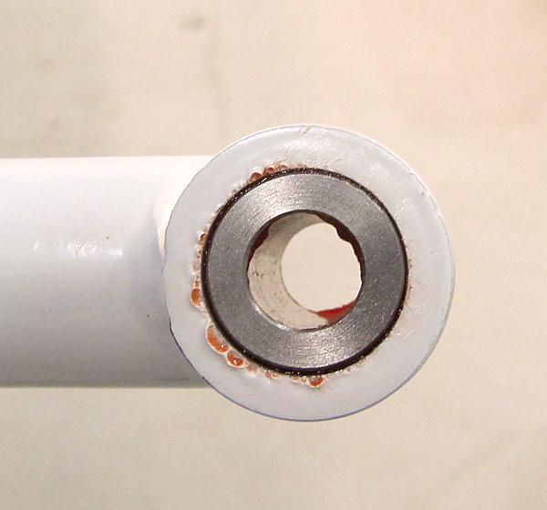
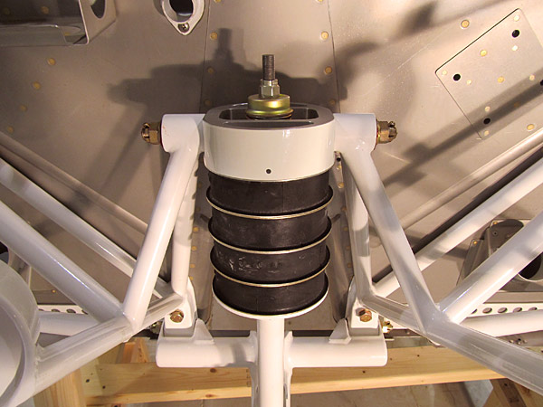 See how flat the compression spring (SPRING-0003) is; it's just about even with the top of the (U-01407) elastomer pad. |
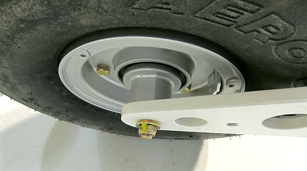
 The (MS21083-N5) lock nut on the (AN5-21A) bolt that holds the (WD-1031) axle flange onto the (U-01406) nose gear leg was final torqued to 84 inch/pounds (70"/lbs. + 14"/lbs. drag = 84"/lbs.). The nut was torque sealed. |
 These are the parts that will install the (U-01430) nose wheel fork to the (U-01406) nose gear leg. |
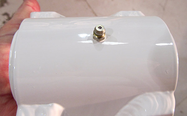 As per step 1, on page 40A-07, figure 1, I put Loctite 567 thread sealant on the (MS 15002-1) grease fitting and then threaded it into the hole in the front of the (U-01430) nose wheel fork assembly. |
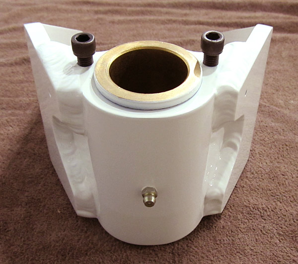 Two (5/16-24x3/4) screws were attached to the top of the (U-01430) nose wheel fork. |
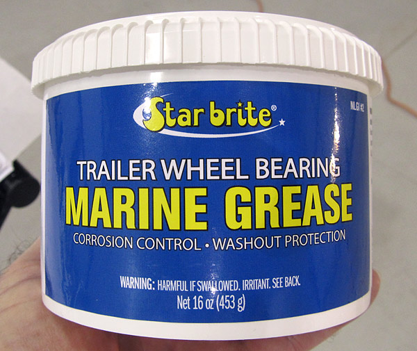 The next step is to grease the spindle of the (U-01406) nose gear leg and marine trailer grease is recommended. |
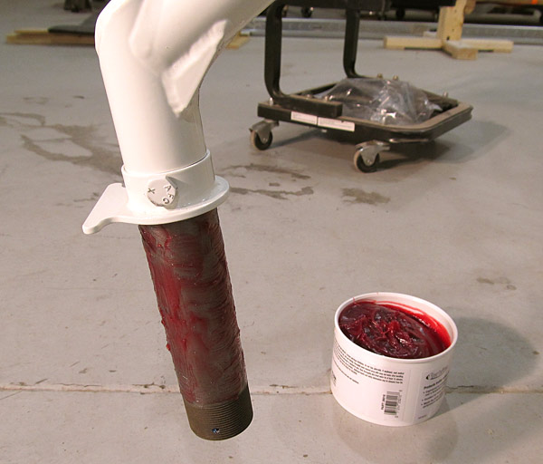 As per step 2, on page 40A-07, figure 1, the spindle on the (U-01406) nose gear leg was greased with Starbrite trailer marine wheel bearing grease as indicated. |
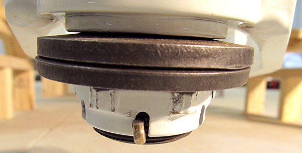
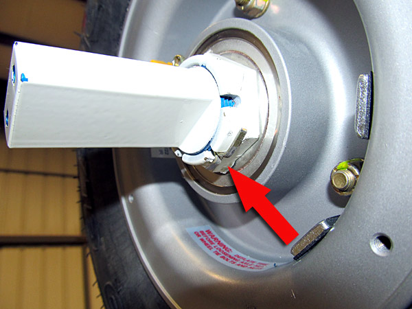
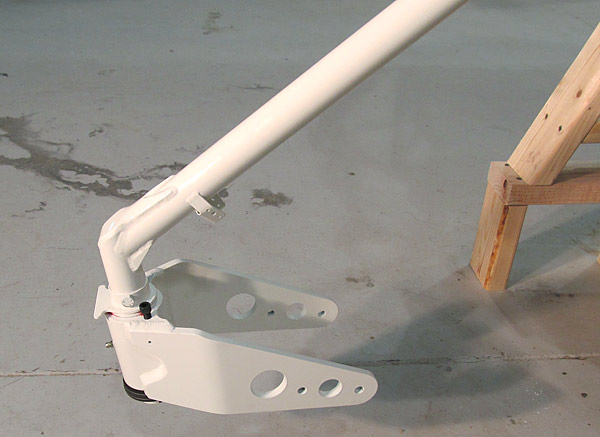 As per step 3, on page 40A-07, figure 1, I slid the (U-01430) nose wheel fork and the two (K2750-O-219) belleville washers onto the spindle of the (U-01406) nose gear leg being careful to observe proper orientation) and then threaded the (MS21025-24) nut on. |
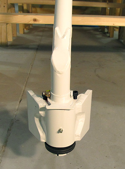 The (MS21025-24) nut has not been final torqued yet, some calibration in step 4 has to be accomplished. |
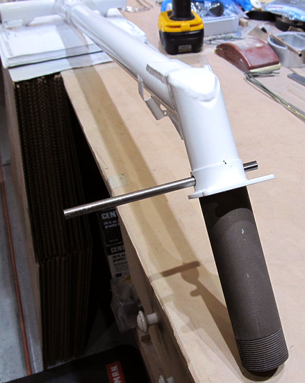
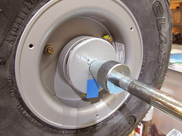
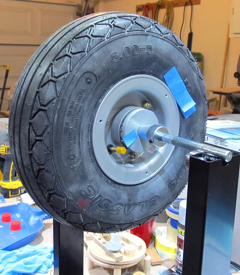
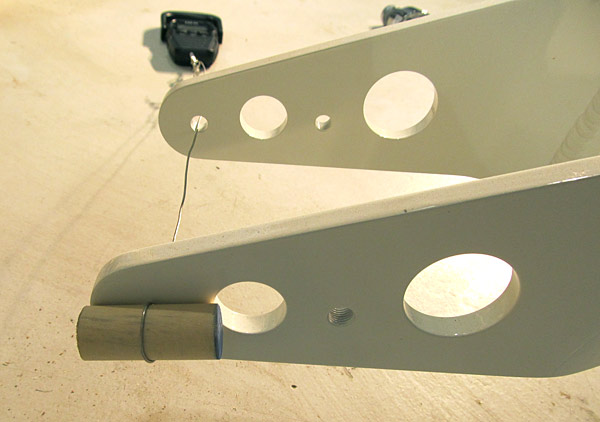 As per step four, on page 40A-07 of the builder's manual, the tension of the (U-01430) nose gear fork must be adjusted so that a force of 26 pounds is required to rotate the nose fork around the (U-01406) nose gear spindle. |
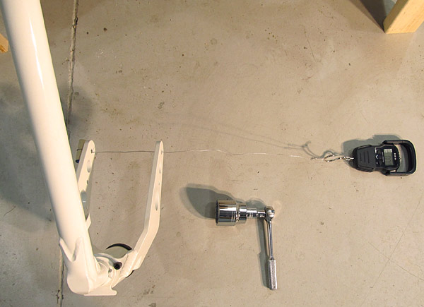 Here is another view of the calibration set up. |
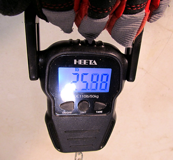 25.98 pounds is close enough! |
 The (MS21025-24) castle nut was secured with a (MS24665-360) cotter pin. |
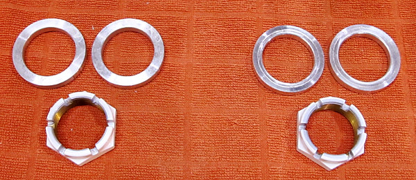
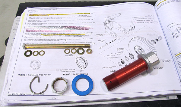 These are the parts that will be used in the installation of the nose gear wheel/tire. |
 As per step two, on page 40A-08 of the builder's manual, the (U-00024) axle was slid through the bearings of the nose wheel, then the (U-00711) axle spacer was slid over the end of the axle and the (MS21025-20) castle nut was threaded onto the axle. (All as depicted in figure three on page 40A-08.) |
 As per step three, on page 40A-08, the (MS21025-20) axle nut was tightened until all play was gone and the wheel rotated freely, (making sure that the rubber seal did not move on either side). |
 As per step four, on page 40A-08, the (U-00712) axle nut pin was inserted into the hole in the (U-00024) axle as depicted in figure three on page 40A-08. |
|
 I final torqued the (MS21083-N6) lock nut on the (AN6-65A) nosewheel axle bolt to 104 inch/pounds (90"/lbs. + 14"/lbs. drag = 104"/lbs.) and torque sealed the nut. |
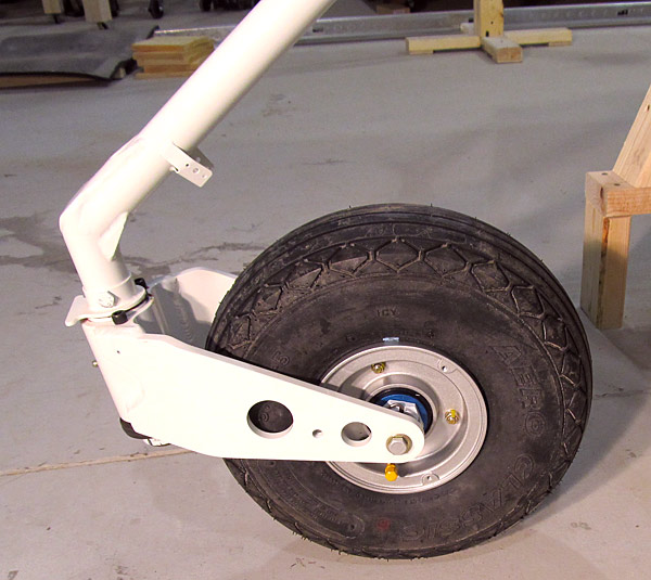
 The nose wheel is installed, main gear is next! |
 These are the parts that will be used to install the main landing gear tire/wheel assemblies to the main landing gear. |
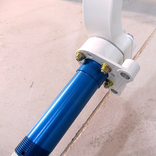
 This is the (U-01401-L) left landing gear leg. |
 This is the (U-01401-R) right landing gear leg. |
 As per step one, on page 40A-09, referencing figure one, the (U-00003) bracket mount, the (U-00009) axle, and the Brake Torque Plate are bolted to the (U-01401-L) left main landing gear leg with the hardware called out in figure one. |
 As per step one, on page 40A-09, referencing figure one, the (U-00003) bracket mount, the (U-00009) axle, and the Brake Torque Plate are bolted to the (U-01401-R) right main landing gear leg with the hardware called out in figure one. |
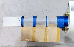
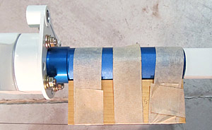
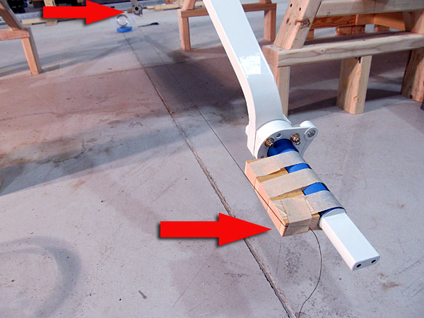 As per step two, on page 40A-09, referencing figure two, checking for correct alignment of the axles is achieved by attaching (1.5" x 4" x 3/4") wooden blocks to the front of each axle assembly with tape. |
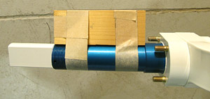
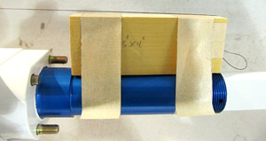 Here is a closer view. |
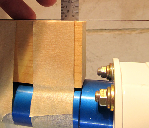 A measurement is taken between the tight string and the wood block edge on the left gear side; this measurement is called "Y". |
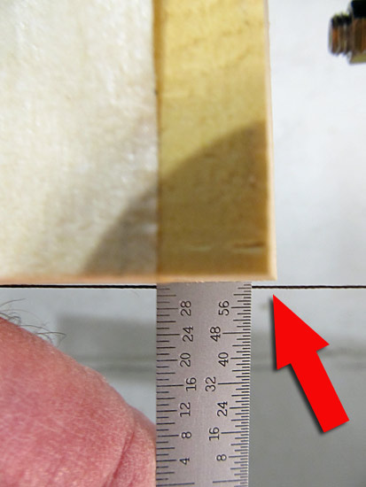 A measurement is taken between the tight string and the wood block edge on the right gear side; this measurement is called "Y". |
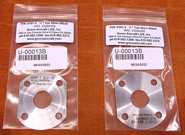 The .05" U-00013B axle shims have arrived; they are from Grove Aircraft LGS, Inc. |
 After determining the thick side of the shims I marked them with a sharpie so that I would know which side to face forward. |
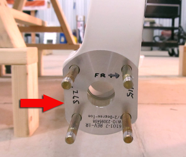
 As per step three, on page 40A-09, the 0.5" (U-00013B) axle shims were placed between each (U-00009)axle and the (U-01401-L and U-01401-R) left and right main gear legs. |
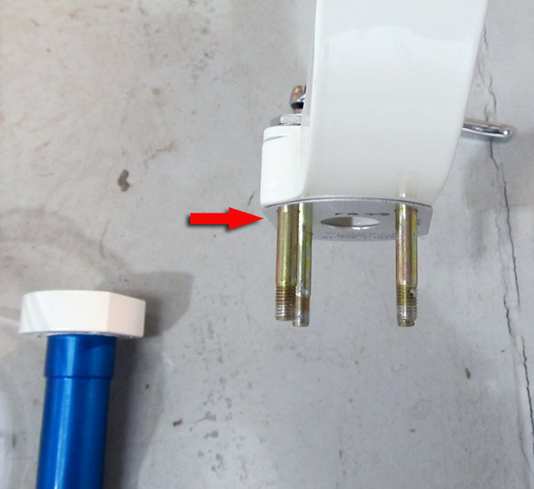
 After the .05" (U-00013B) axle shims are installed and the axle assemblies bolted into place, a recheck of the alignment is needed. |
 There is now no gap between the string and the wood blocks, therefore axles are in alignment now. |
 The (MS21042-4) lock nuts were final torqued to 99 inch/pounds (85"/lbs + 14"/lbs drag= 99"/lbs) and torque sealed. |
 The right gear axle final torqued. |
 This is the hardware used for attaching the main gear wheels to the axles. |
 As per step one, on page 40A-10, referencing figure one, the (U-405) axle spacers were slid onto the (U-00009) axles of the left and right landing gear. |
 I put a small mark on the axle so I would know where the hole for the cotter pin was. |
 The (MS24665-359) 1 3/4" cotter pins have arrived and I can finish the main wheel/tire assembly process. |
 The cotter pins are installed now. |
 All of the wheels are installed. |
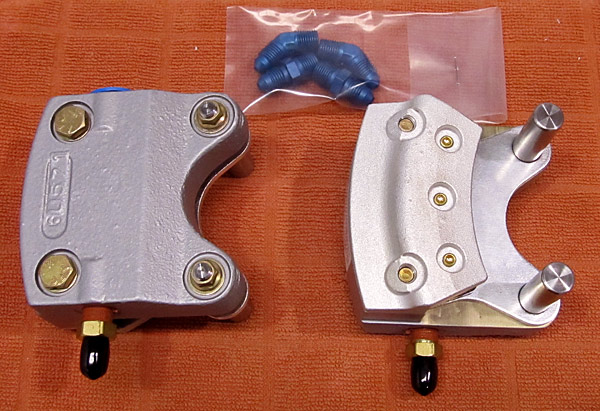 Time to install the brake calipers. |
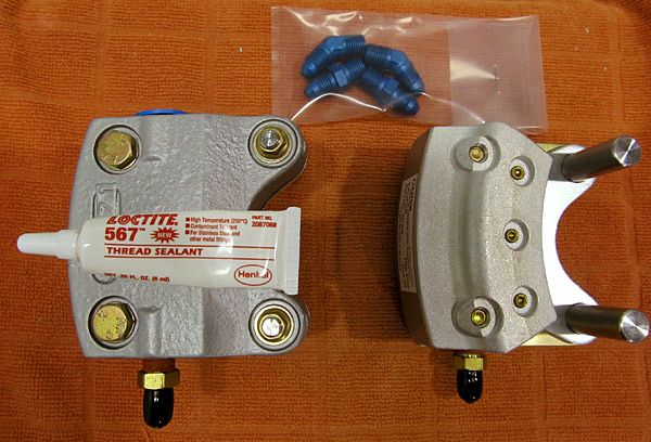 The instructions in step two, on page 40A-10 call for high temp sealant such as Permatex (59214) to be applied to the male threads of the fittings but I have Loctite (567) which is equivalent. |
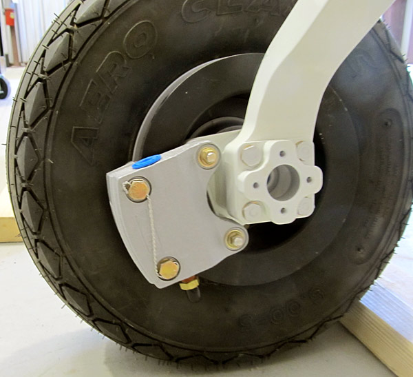
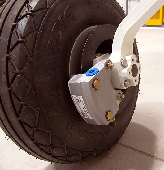 As per step three, on page 40A-10, referencing figure two, the studs of the brake caliper assemblies were slid into the brake torque plates. The back plates were placed behind the brake discs, and then the back plates and the brake caliper assemblies were bolted together using the hardware called out in figure two. |
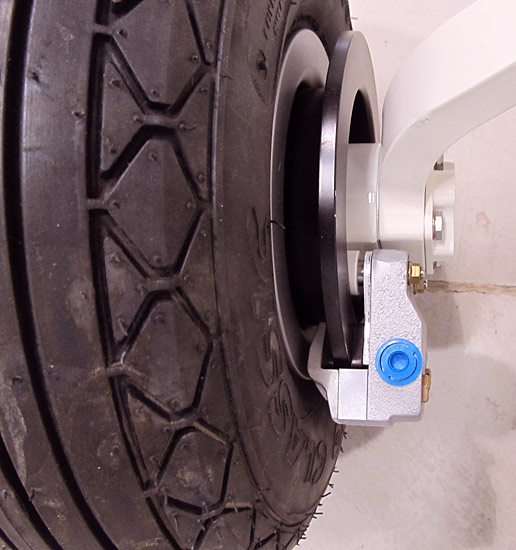 This is a view from above. |
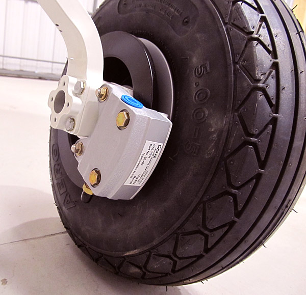 Brake calipers installed on the right gear. |
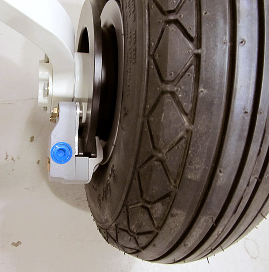 This is a view from above. |
 The (AN4H-15A) bolts were final torqued to 104 inch/pounds (90"/lbs + 14 "/lbs drag= 104"/lbs). |
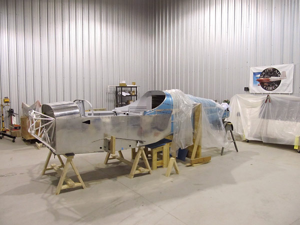
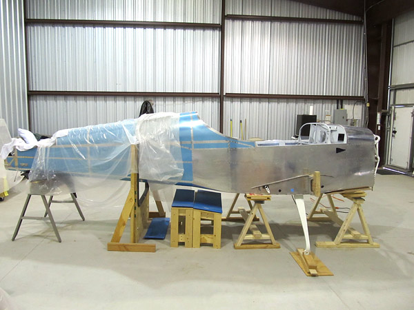
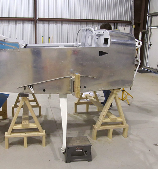
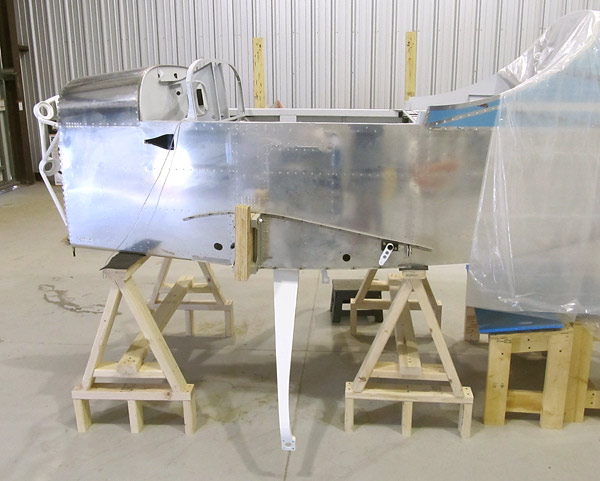
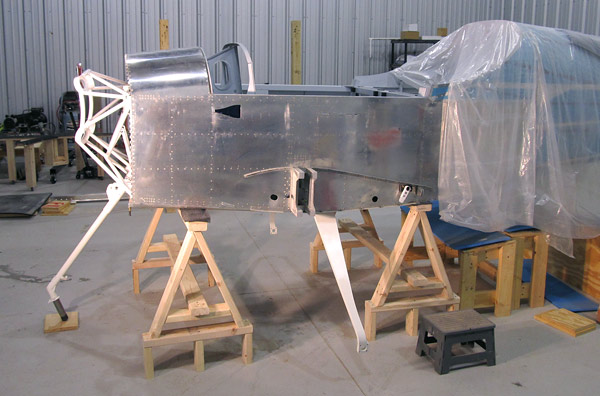
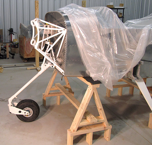
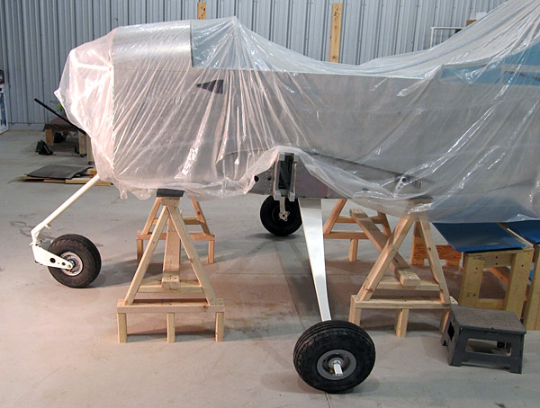
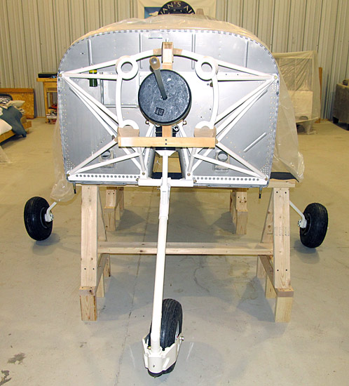
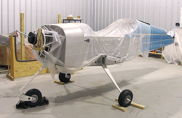 Well, this is an exciting moment, the fuselage is finally standing alone on it's landing gear! |
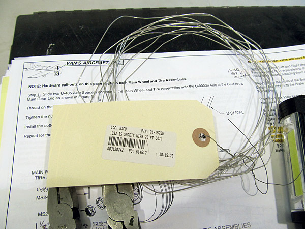 I safety wire all of the bolts with this .032" stainless steel safety wire. |
 As per step two, on page 40A-10 of the builder's manual, and referencing figure two, I safety wired the AN4H-15A bolts on the Grove brake caliper assemblies with .032" stainless steel safety wire. |
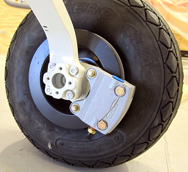 This is the right main gear. |
Aerotoons©, is a participant in the Amazon Affiliates Program. For more information please visit our terms of use and policies page.
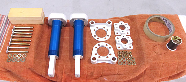
 It took 1 year, 3 months to receive the finish kit which includes the engine mount, brakes, and landing gear parts.