Koga's Zero

WWII poster

You seldom hear much about the Alaskan territory in the scope of World War II but in reality it was considered to be very strategic by both the Americans and Japanese during that time. The famous U.S. General Billy Mitchell stated to the U.S. Congress in 1935, "I believe that in the future, whoever holds Alaska will hold the world. I think it is the most important strategic place in the world."

The strategic thinking of the day was that whoever controlled the area would have an advantage over the opposition by using it as a jump off point to launch possible strikes from the north against the respective homelands. Thus began the "Aleutian Islands Campaign" to gain control over the Aleutian Islands (part of the Alaskan Territory) in the Pacific portion of World War II.

Alaska Map

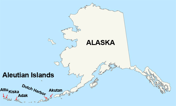
On June 3, 1942 a small Japanese force occupied the islands of Attu and Kiska. Admiral Isoroku Yamamoto assigned Vice-Admiral Boshiro Hosogaya to the task of taking the Aleutians and provided him a force of two small aircraft carriers, five cruisers, twelve destroyers, six submarines, four troop transports, and supporting auxiliary ships.

Hosogaya was to first launch an air attack against Dutch Harbor (June 3, 1942), then follow with an amphibious attack upon the island of Adak, 480 miles to the west.

Hosogaya was ordered to destroy all American forces and facilities found on Adak and then return to their ships and to become a reserve for two additional landings: the first on Kiska (June 6,1942), 240 miles west of Adak, the other on the Aleutians' westernmost island, Attu (June 7,1942), 180 miles west from Kiska.

Crash Site

Here is where the story of the captured Japanese Zero begins...

Tadayoshi Koga

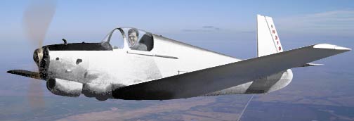
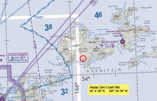
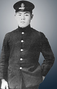
The Akutan Zero (piloted by 19 year old flight petty officer first class Tadayoshi Koga), also known as Koga's Zero, and the Aleutian Zero, was a type 0 model 21 Mitsubishi A6M Japanese Zero fighter plane (serial number 4593) that crash-landed on Akutan Island, Alaskan Territory, during World War II.

Koga was part of a three-plane raid against Dutch Harbor that was launched from the Japanese aircraft carrier Ryujo on June 3, 1942. At some point during the raid Koga's airplane was hit by small arms fire which severed the engine's return oil line immediately causing a trail of oil and smoke.

In order to prevent the engine from seizing Koga reduced his airspeed and flew with his fellow airman approximately 25 miles east of Dutch Harbor to a designated emergency landing airfield on Akutan Island.

Koga Shot Down

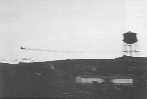
At Akutan the three Zeros circled a grassy flat area about a half mile inland from Broad Bight and decided that Koga should land on what was believed to be solid ground. (In reality it was muddy and swampy ground and the decision to land with landing gear extended proved to be a fatal mistake.)

The plane's landing gear mired in the water and mud, causing the plane to flip upside down and skid to a stop. Although the aircraft survived the landing nearly intact, Petty Officer Koga died on impact, probably from a broken neck or a blow to the head.

Koga's wingmen, circling above, had orders to destroy any Zeros that crash-landed in enemy territory, but as they did not know if Koga was still alive, they could not bring themselves to strafe his plane.

Koga Zero Wreckage

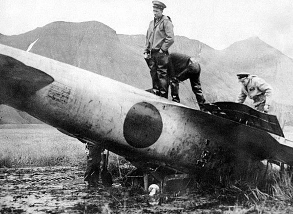
The wreckage laid undiscovered for over a month but on July 10, 1942 it was spotted by Lieutenant William "Bill" Thies (a Catalina PBY pilot) and efforts began to salvage the airplane.

On July 15, 1942 the airplane had been transported to Dutch Harbor where it was turned right-side up and cleaned then shipped to Seattle. From there, it was transported by barge to Naval Air Station North Island near San Diego where repairs were secretly and carefully carried out to make the airplane airworthy again.

The three-blade Sumitomo propeller was dressed and re-used and the Zero's red Hinomaru roundel was repainted with the American blue circle-white star insignia.

The Zero was fit to fly again on September 20.

Koga Zero Wreckage Rebuilt

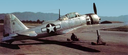
On September 20, 1942 (2 months after the Zero's capture), Lieutenant Commander Eddie R. Sanders took the Akutan Zero up for its first test flight. He would make 24 test flights between September 20 and October 15.

The very first flight exposed weaknesses of the Zero which our pilots could exploit with proper tactics ... immediately apparent was the fact that the ailerons froze up at speeds above 200 knots so that rolling maneuvers at those speeds were slow and required much force on the control stick. It rolled to the left much easier than to the right. Also, its engine cut out under negative acceleration due to its float-type carburetor.

We now had the answer for our pilots who were being outmaneuvered and unable to escape a pursuing Zero: Go into a vertical power dive, using negative acceleration if possible to open the range while the Zero's engine was stopped by the acceleration. At about 200 knots, roll hard right before the Zero pilot could get his sights lined up.

American tacticians were able to devise ways to defeat the Zero, which was the Imperial Japanese Navy's primary fighter plane throughout the war.

The Akutan Zero has been described as "a prize almost beyond value to the United States", and "probably one of the greatest prizes of the Pacific war". Japanese historian Masatake Okumiya stated that the acquisition of the Akutan Zero "was no less serious" than the Japanese defeat at the Battle of Midway, and that it "did much to hasten Japan's final defeat".

The Akutan Zero was destroyed during a training accident in February 1945. While the Zero was taxiing for a take-off, a SB2C Helldiver lost control and rammed into it. The Helldiver's propeller sliced the Zero into pieces. From the wreckage, William N. Leonard salvaged several gauges, which he donated to the National Museum of the United States Navy. The Alaska Heritage Museum and the Smithsonian National Air and Space Museum also have small pieces of the Zero.

Specifications Type 0 Model 21 Mitsubishi A6M Zero
• Manufacturer: Mitsubishi
• First Flight: Test flown April 1, 1939. Entered service on August 14, 1940 with 10,815 being produced.
• Crew: 1
• Wingspan: 39 ft. 4 in. (12.0 m)
• Length: 29 ft. 9 in. (9.06 m)
• Height: 10 ft. 0 in. (3.05 m)
• Maximum Takeoff Weight: 5313 lb. (2,410 kg)
• Empty Weight: 3704 lb. (1,680 kg)
• Powerplant: 1 × Nakajima Sakae 12, 14 cylinder double rowed radial engine, 950 hp. (709 kW)
• Fuel capacity: 137 gal. (520 L) internal + 85 gal. (320 L) ventral drop tank
Performance
• Never Exceed speed: 410 mph 356 kt (660 km/h)
• Maximum speed: 331 mph, 287 kt (533 km/h) at 14,930 ft. (4,550 m)
• Cruise speed: 207 mph, 180 kt
• Rate of Climb: 3,100 ft/min (15.7 m/s)
• Service Ceiling: 33,000 ft. (10,000 m)
• Range: 1929 mi, 1675 nm (3,105 km)
Armament
• Guns: 2× 7.7 mm (0.303 in) Type 97 aircraft machine guns in the engine cowling, with 500 rounds per gun.
• Cannons: 2× 20 mm Type 99-1 cannon in the wings, with 60 rounds per gun.
• Bombs: 2× 132 lb (60 kg) bombs or 1× fixed 551 lb. (250 kg) bomb for kamikaze attacks.
 

Here is a book about Koga's Zero: Koga's Zero: The Fighter That Changed World War II : Found in Alaska – by Jim Rearden


Flight Simulators of Yesteryear

Modern Flight Simulators

We've all seen pictures of simulators that are in use today; modern, highly sophisticated machines that make you feel as if you were actually flying.

They are useful training aids and help pilots polish their flying skills and procedures in many areas such as cockpit resource management, flying instrument approaches, dealing with emergencies and abnormal situations, familarization with new aircraft, and flight crew coordination .... all from the safety of being on the ground.

They are amazing machines and have developed considerably since the beginning when men and women started flying. Even the modern desktop and laptop computer flight simulators are far ahead of what was used in the past for ground based flight training.

Have you ever wondered what some of the early simulators were like? I have and found some interesting simulators from yesteryear.

Antoinette Trainer

This is a photograph of one of the earliest ground simulators (photo circa 1911).

A student is seated in a "Tonneau d'apprentissage", or "Antoinette", at the École de Pilotage (Antoinette Piloting School)
at Mourmelon-le-Grande, France.

Two half-sections of a barrel were moved manually which represented the pitch and roll of an airplane. The student pilot was then required to line up a reference bar with the horizon.

Breese Penguin

Although not a true synthetic simulator, this is a 1917 Breese Penguin.

It was used to give student pilots the feel of aircraft controls at near flying speeds without the danger of actual flight. (The Penguin's wings were too short and its engine too small to allow it to fly.)

The "Penguin" was intended to be just as unmanageable as real aircraft, thus they had no brakes or steerable wheels - which made them quite difficult to control.

Ruggles Orientator

This is the 1917 "Ruggles Orientator".

It consisted of a seat mounted within a gimbal ring assembly that enabled full rotation of the student pilot in all three axes (pitch, yaw, and roll) and a fourth additional vertical movement.

All motions were controlled by rudder bars and sticks by the instructor and student pilot which operated electric motors to produce the desired flight attitudes.

The goal was to train students to recognize and recover from unusual attitudes that might be encountered in flight.

*Note the position of the student pilot in the far right simulator and the fact that there is no instructor!

Link Ad

The next major advancement in simulators came in 1929. The Link trainer invented by Edwin Albert Link is easily one of the most recognized early simulators.

They were produced and used from 1934 through the late 1950's.

Just as this ad says, "Every aviation cadet receives instruction in a Link Trainer"....and that's not an exaggeration because 10,000 units were produced and thousands of pilots trained in them, especially during WWII.

Link Exterior

Known as the "Blue Box" to the student pilots, these trainers kept pace with the increased instrumentation and flight dynamics of aircraft of their period, but retained the electrical and pneumatic design fundamentals pioneered in the first 1929 Link prototype.

There are two major components to the trainer, the first is the trainer itself which is connected via universal joint to the base.

Inside the cockpit is a single pilot's seat, stick and rudder controls, and a full suite of flight instruments.

The base contains several items: complicated sets of air-driven bellows to simulate 3 axis motion, an air compressor (powers the motion bellows and some of the aircraft instruments), and a "Telegon Oscillator" which controls the remaining instruments.

Link Interior
Link Instructor station

The second major component is an external instructor's station, which consists of a large map table, a repeated display of the main flight instruments, and a moving marker known as a "crab."

The crab moves across the glass surface of the map table, plotting the pilot's track.

The pilot and instructor would communicate with each other via headphones and microphones.

Both the trainer and the instructor's station are powered from standard 110VAC/240VAC power outlets via a transformer, with the bulk of internal wiring being low voltage. Simulator logic is all analog and is based around vacuum tubes.

The Link trainer is really the beginning of modern flight simulators because they all incorporate many of the innovations that were found in this trainer....3 axis motion, pilot / instructor radio communcation, flight tracking, full cockpit instrumentation, and to some extent aircraft specific duplication (the instrument layout of the ANT18 Link is that of the AT-6 and SNJ aircraft). All that would be needed to complete the formula is a visual element.

Boeing 377

The first airline to own a full aircraft simulator was Pan American Airways in 1948.

Curtiss-Wright developed the simulator for use in training crews flying the Boeing 377 Stratocruiser.

No motion or visual systems were installed, but in all other respects the simulator duplicated the appearance and behavior of the Stratocruiser cockpit.

Instructors could introduce emergencies or abnormal situations on a fault insertion panel or "trouble box" to train flight crews procedures and coordination in order to solve in-flight problems. In addition, complete routes could be flown, as in real life, using the same navigational aids.

BOAC Simulator

By 1958 it was all beginning to come together. BOAC (British Overseas Airways Corporation) had contracted Redifon to develop a full motion simulator for the Comet IV aircraft.

The simulator was beginning to look more like what is in use today but realistic visual aspects were yet to be used.

It wasn't until 1962 when the first color system was produced by Redifon, utilizing television technology, that simulators had believable visual references that we are familiar with today.


Here is the joystick that we like and use: Extreme 3D Pro Joystick
I've used this yoke too, it really is a "classic": CH Products Flight Sim Yoke
These are the rudder pedals that we use: CH Products Pro Pedals

Light Gun Signals Used In Aviation

Do you know the light gun signals that are used in case of a radio failure or if your aircraft is not equipped with a radio?
Air Traffic Control (ATC) will use a signal lamp to give you instructions and clearance limits. The light gun has a focused bright beam and is capable of emitting three different colors: red, white and green.
You have to look closely but they are visible from a surprising distance away. These colors may be flashed or steady, and have different meanings to aircraft depending if you are in flight or on the ground.
Pilots can acknowledge the instructions by "rocking" their wings, moving the ailerons if on the ground, or by flashing their landing or navigation lights during hours of darkness.

Here's a quick refresher to the signals used...

Flashing Green On The Ground:Cleared to taxi Flashing Green In The Air:Cleared to approach or return to land
Cleared to taxi Cleared to approach airport, or return to land.
Steady Green On The Ground:Cleared for takeoff Steady Green In The Air:Cleared to land
Cleared for takeoff. Cleared to land.
Steady Red On The Ground:Stop Steady Red In The Air:Give way to aircraft, continue circling
Stop Continue to circle, give way to other aircraft.
Flashing Red On The Ground:Immediately taxi clear of runway in use Flashing Red In The Air:Airport unsafe, do not land
Immediately taxi clear of runway in use. Airport unsafe, do not land.
Alternating Red/Green On The Ground:Exercise extreme caution Alternating Red/Green In The Air:Exercise extreme caution
Exercise extreme caution. Exercise extreme caution.
Flashing White On The Ground:Return to starting point. There is no Flashing White used In The Air.
Return to starting point.

Janet Flights

Living in Las Vegas one can't help but notice the "JANET" flights arriving and departing McCarran Airport several times a day but did you know why they call them "JANET"?

According to legend the "JANET" call sign stands for Just Another Non Existent Terminal.
It is also said to be the wife's name of a CIA agent in charge of "Area 51".... no-one knows for sure.

The Janet missions started as far back as 1955 with the founding of the secret airbase "Watertown Strip", but eventually became official in 1972 with a single Douglas DC-6B, followed by an additional DC-6B in 1976.

Janet Flight 737-600 by Twistedpictures1

The current fleet consists of several Boeing 737-600's (painted white with a red side stripe).

Janet Flight Beechcraft 1900 by Tomás Del Coro

They also operate Beechcraft 1900 and 200 airplanes (painted white with a blue side stripe).

Janet flights operate from McCarran and fly to several locations including "Area 51" (airport code KTKM). (The "Area 51" flight at best lasts only 25 minutes and never gets much higher than 15,000 feet.)
Janets use the airline code WWW plus a three digit flight number however after handoff from approach or departure control the name often changes.

Other Janet Flight Destinations:

• Edwards Air Force Base
• Nellis Air Force Base
• San Nicolas Island
• Point Mugu Naval Air Station
• Palmdale Flight Test Installation, AF Plant 42
• China Lake Naval Air Weapons Station
• Alamogordo-White Sands Regional Airport
• Salt Lake City International Airport
• Wright-Patterson Air Force Base
• Nut Tree Airport KVCB
• Creech Air Force Base
• Hill Air Force Base

Interestingly enough, there were never many Boeing 737-600's produced (only 69) with Scandinavian Airlines (SAS) being the launch customer in 1995 receiving the first aircraft on September 18, 1998. The final B737-600 was delivered to WestJet in 2006.


Hand Signals Used In Aviation

Have you ever heard the old saying; "It's easy enough flying there but the hard part is finding your way once you're on the ground"?

Thankfully there are men and women on the ground who's job it is to help. The military, airlines, and general aviation ramp personel all use the same basic hand signals to communicate taxi directions to you.

It makes no difference if it is daytime or nightime, the signals are the same but at night lighted wands are used instead of hands or unlit wands.

You may or may not know what the aviation hand signals are or what they mean so I thought it would be interesting to take a look at some of the different signals that are in use...

All Clear All Clear Start Engine Start Engine Face Me Face Me Taxi Forward Taxi Forward Taxi Slower Taxi Slower Turn Right Turn Right
Turn Left Turn Left Stop Stop Set Brakes Set Brakes Cut Engine Cut Engine Chocks In Chocks In Chocks Out Chocks Out

There's more hand signals in use but if you remember some of these basic ones you'll be "good to go!"

Clear To Go

Mooney Mite M-18

Mooney Mite Ad

Did you ever wish you could have your own personal "fighter", an airplane that would fly at speeds of 120-130 m.p.h., sipped 3.5 gallons of gas per hour, and only cost $1995?

Well, Al Mooney was sure that you would so he designed a cute little single place airplane called the Mooney M-18 "Mite".

It was certified and produced from 1948 to 1955 with a total of 283 Mites being built.

I first saw a Mooney Mite when I was a teenager; it was hanging from the rafters in a barn that was owned by a business customer of my Father. It was one of several other airplanes being stored there and was painted yellow.... I'll never forget it.

It seemed a shame that the Mite was reduced to "flying" from the rafters. I was told that Mooney Mites were originally powered by Crosley "Cobra"- COpper BRAzed automobile engines. I found that interesting because my brother just happened to own a 1952 Crosley Custom Sedan at the time!

Mooney Mite Engine

As I recall, the performance of the auto was poor with the 25- h.p. liquid cooled engine so I imagine that the performance of the M-18 Mite might not be spectacular either. As a matter of fact, the performance of the Crosley engine (now called a Mooney CC46M-2, see photo on the left) was inadequate which caused Mooney to exchange the engines in the first 10 production Mites with a more reliable 65-h.p. Lycoming (0-145-B2) engine.

Later models also used a Continental (A65-12, or -8) when the Lycoming engine became unavailable.The performance with the new engine increased the cruise speed from 85 m.p.h. to 125 m.p.h., rate of climb increased from barely 300 f.p.m. to 1000 f.p.m.

Al Mooney was well on his way to producing a great flying airplane. It did fly well but sadly the sales were not there and production ended in 1955.

Mooney Mite Prototype

This photo is the M-18 prototype with a Crosley engine. It also happens to be the same airplane featured in the ad at the beginning of the article. As you can see it was later converted with the aircraft engine also.

Mooney Mite Panel
Mooney Mite M-18
• Manufacturer: Mooney Aircraft Corporation
• First Flight: 1947
• Crew: 1
• Wingspan: 26 ft 10½ in.
• Length: 17 ft 7¼ in.
• Height: 6 ft 2½ in.
• Maximum Takeoff Weight: 780 lbs.
• Empty Weight: 500 Lbs.
• Powerplant: One, Continental Motors C-65 wooden propeller, 65 hp
• Total Fuel: 11 Gal.
Performance
• Maximum speed: 138 mph (Vne)
• Cruise speed: 125 mph
• Rate of Climb: 1090 ft/min
• Service Ceiling: 19,400 Ft.
• Range (@125 mph): 390 Miles.
• Stall Speed: 45 mph
 

Click here to go back to newer posts.......▶
◀.......Click here to go back to older posts