Wings

Van's Aircraft offers a "QuickBuild" option for the wings. I decided that in order to have the airplane flying in the quickest time it would be nice to have the wings quick built by Van's quick build team called "Famous Secret" located in the Phillipines. We also ordered the quickbuild fuselage at the same time.

RV14A Empennage KitIt took 8 months, almost to the day, from the time we ordered the quickbuild kits until we received them at our hangar.

Wingstand

I built a wing stand so that when the wings arrive they can be placed in this cradle and moved around the hangar with ease.

Delivery Day!

RV14A Quickbuild Delivery

We made arrangements to have our quickbuild kits delivered by Tony Partain. They did a great job and they really know what they are doing!

RV14A Quickbuilds On The Truck

Here you can see our kits loaded on the truck. We were the fourth delivery that they made on this trip.

RV14A Quickbuilds Unloading From The Truck

There were only three of us at the hangar to do the unloading: the driver, my wife, and myself.

The fuselage was unloaded using a hoist system but the wings were unloaded by hand. We had no problems.

That wingstand really came in handy and made the job go smoothly!

*I wouldn't want less than three people here because handling the wings would be very tricky with only two people present.

RV14A Quickbuild Fuselage Side View

The wings are in the hangar!

RV14A Quickbuild Flaps

*The flaps, ailerons, landing light lens covers, hardware, and skin parts were all shipped inside of the fuselage.


Fabricating Aileron Torque Tube To Bellcrank Pushrods

As per step one, page 23-03 of the builder's manual two (CS-00012) aileron torque tube to bellcrank pushrods are to be fabricated from two (AT6-035x1 1/8) six foot long aluminum tubes.
The tubes are to be cut to a length of 64 1/4" each.

Fabricating Aileron Torque Tube To Bellcrank Pushrods

The lay out lines are drawn now to do the cuts!

Cutting Torque Tube To Bellcrank Pushrods With Bandsaw

I cut the two (CS-00012) torque tube to bellcrank pushrods using our bandsaw.
I sawed close to the lines drawn and then final sized and "squared up" the cuts using a stationary disc sander. The edges were then deburred.

Bellcrank To Aileron Pushrods

Since I was in the cutting mood, I jumped to step 1, page 23-04 of the builder's manual in order to fabricate two (CS-00013) bellcrank to aileron pushrods.
These are cut down from a single 48" piece of powder coated (ST4130-035x1/2x48) tubing stock.
Each of the (CS-00013) bellcrank to aileron pushrods are to be 21 3/8" long (see figure 1, page 36-04) so I rough cut the tubing with a hacksaw and then final sized and "squared up" the ends on our stationary disc sander. Each of the edges were deburred after the process as well.

Torque Tube To Bellcrank Pushrods Cut To Size

The two (CS-00012) torque tube to bellcrank pushrods have been cut to size, now for the (CS-00013) bellcrank to aileron pushrods (CS-00013) to be cut...

CS-00013 Bellcrank To Aileron Pushrod Cut

The two (CS-00013) bellcrank to aileron pushrods have been cut to final size.
Internal priming to go...

Preparing CS-00012 Pushrods For Priming

I scuffed the exterior surfaces of the two (CS-00012) torque tube to bellcrank pushrods with red ScotchBrite pads and washed them with acetone so that they could be primed later, but now I have to prime the interiors of the pushrods now.


Rubber Stopper

In order to make priming the interior of the (CS-00013) bellcrank to aileron pushrods less messy, I found two rubber stoppers at the hardware store so that I could plug up the ends and "swish" the paint around without getting paint all over the place....it helped but it's still a messy process!

Priming The Interior Of CS-00013

Here I am priming the interiors of the two (CS-00013) bellcrank to aileron pushrods.

*I used PTI Zinc Chromate green primer.

Rubber Stopper

This rubber stopper was much harder to find but our local hardware store had some!

Priming The Interior Og CS-00012

Here I am priming the interiors of the two (CS-00012) torque tube to bellcrank pushrods.

*I used PTI Zinc Chromate green primer.

PTI Zinc Chromate Primer

This is the PTI Zinc Chromate primer that I used to paint the interiors of the pushrods.

PTI Zinc Chromate Primer

This is the PTI Zinc Chromate primer that I used to paint the interiors of the pushrods.

Title

Drip dry for a couple of days!


Drilling Template

I reproduced drill templates found in figure one on page 23-11, of the builder's manual out of manilla folder material so that I wouldn't have to reuse the cutout from the manual over and over again. It saved some time because I could just tape the template on the pushrod ends and not have to worry about being careful to tape and then un-tape the template as the center punching process progressed.

*Be sure to double check the accuracy of the printed scale on the page for your dimensions (1/2" x 3 9/16") before you use the templates. There are six "cross hair" guides per template.

Tape templates To Pushrods

As per step 2, on page 23-03 of the builder's manual, I aligned the pushrod drill template with the ends of the (CS-00012) torque tube to bellcrank pushrods and then secured it with clear tape.

The center punching process can begin!

Center Punching Pushrods

I used a spring loaded center punch to punch each of the six "cross hairs" that will be drilled in the next step.

#40 Drilling Template Guided Holes In Pushrods

As per step 2, on page 23-03 of the builder's manual, six #40 pilot holes were drilled into the ends of the (CS-00012) torque tube to bellcrank pushrods.

All of the holes were deburred after drilling.

Vee Block

I used a Vee Block to help keep things steady as I drilled.

VA-111 Threaded Rod Ends

Each of the torque tube to bellcrank pushrods will receive a threaded rod end fitting which is supposed to be inserted into the ends of the pushrod and have six #30 holes drilled into them; before I do that I want to debur each one and scuff the surfaces so that they can be primed later.

There are four (VA-111) threaded rod end fittings. These are the four (VA-111) threaded rod end fittings. They will be attached to the (CS-00012) torque tube to bellcrank pushrods.


VA-111 Threaded Rod Ends

After the deburring and scuffing process was done I used a sharpie to mark reference lines on the threaded rod end fittings where the torque tube to bellcrank pushrod end should line up with the fitting.

*Step 3 and figure 2, on page 23-03 of the builder's manual, show that the proper engagement is when the end of the pushrod coincides with the edge of the taper in the rod end fitting.

Proper End Alignment

According to figure 2, on page 23-03 of the builder's manual, this is what the proper alignment should look like. The taper of the threaded rod end fitting coincides with the end of the torque tube to bellcrank pushrod.

Now it's time to match drill #30 holes into the rod end fittings using the previously drilled #40 holes as guides.

Match Drilling The Rod End Fittings

I used a vee block jig clamped to the table to help support the pieces as I match drilled the #30 holes.

Cleco After Drilling Pilot Hole Upsizing

Clecos were inserted into each new hole as the drilling progressed around the circumference of the pushrod.

I also used the (MD3614M) rod end bearing to help keep the threaded rod end from slipping past the guide lines while drilling.

*Make sure to cover the bearing with something to keep aluminum bits from the bearing surface.

Clecoed Threaded Rod End Fitting

Six done, 18 more to go!

All Torque Tube To Bellcrank Pushrods Match Drilled

All of the torque tube to bellcrank pushrods and rod end fittings have the #30 holes match drilled now.

*Don't forget to mark the ends of the pushrods and the rod end fittings so that everything can be diassembled, deburred, and reassembled in the correct order!

After I disassembled all of the parts and deburred everything, I washed all of the parts with acetone in preparation for priming.

Deburring Pushrods

Debur, debur!

Marking Pushrod Ends

I use vinyl stick on letters to mark the ends of the pushrods and then prime a couple of thin coats and then remove the stickers and then one more thin coat of primer.

It's extra work I know but I really don't like to see the sharpie marker bleed through....you'll see the results a couple of photos down the page.

Marking Pushrod Ends

This is the other end. After everything was marked all of the parts were again washed with acetone in preparation for priming.


Primed Aileron Pushrods

The two (CS-00012) torque tube to bellcrank pushrods and the four (VA-111) threaded rod ends were primed with DupliColor DAP1690 self etching green primer.

Primed Aileron Pushrods

Here's a better shot.


Clecoed Aileron Pushrods For Assembly

I clecoed the four (VA-111) threaded rod ends to the two (CS-00012) torque tube to bellcrank pushrods in preparation for final riveting per step 3, page 23-03 of the builder's manual, and they will be assembled using the hardware callouts shown in figure 2 of the same page...(MSP-42) rivets.

*Remember what I was saying earlier about using the vinyl stickers to mark the ends with? Here you can see what the final look is.

Clecoed Aileron Pushrod For Assembly

Here's the other end.

Clecoed Aileron Pushrods For Assembly

All ready to be riveted with (MSP-42) rivets!


MSP-42 Rivets

In figure 2, page 23-03 of the builder's manual, the rivets that are called for in the assembly of the (CS-00012) torque tube to bellcrank pushrods are (MSP-42) rivets.

As you can see they are blind rivets.

Setting MSP-42 Rivets

I used our CherryMax G-27 hand rivet gun to set the MSP-42 rivets.

CS-00012 Rivet Setting

One set, 23 more to go!

CS-00012 Rivet Setting

There are six (MSP-42) rivets for each end.

CS-00012 Rivet Setting

CS-00012 Rod End Bearings

Figure three, on page 23-03, shows the hardware that is to be installed onto the (VA-111) threaded rod ends.

There are two (AN316-6R) jam nuts and two (MD3614M) rod end bearings for each (CS-00012) torque tube to bellcrank pushrod.

Adjusting CS-00012 Length

After the (AN316-6R) jam nuts and the (MD3614M) rod end bearings were installed, the center-to-bearing-center lengths of the (CS-00012) torque tube to bellcrank pushrods were adjusted to 67 7/16" long. Final adjustments will be made once installed onto the airplane and the jam nuts will be final torqued.


Autopilot Roll Servo Pushrod

In step three, page 56-02 of the builder's manual, the (CS-00019) autopilot roll servo needs to be assembled.

There are five parts that go into the assembly: the servo pushrod tube, two (AN316-4R) jam nuts, and two (M3414M) rod end bearings.

Autopilot Roll Servo Pushrod

The center-to-center bearing length of the (CS-00019) autopilot roll servo pushrod needs to be adjusted to a length of five inches.

I set the length to five inches for now but there may need to be some final adjustments made once the assembly is installed and the jam nuts will be final torqued and marked with torque seal.

*The two nuts need to be torqued to a value between 14-20 inch/pounds.

Autopilot Roll Servo Pushrod

I labled the (CS-00019) autopilot roll servo pushrod with the number "19".


Bellcrank To Aileron Pushrods

Back to work on the (CS-000013) bellcrank to aileron pushrods; I need to mark guide points in order to drill two sets of holes on each end of the two pushrods so that threaded rods can be attached later.

One set of holes needs to be located 13/32" from the ends, and another set of holes needs to be marked 7/32" from the ends but oriented 90° from the first set of holes.

*The measurements can be found by refering to figures one and two on page 23-04 of the builder's manual.

Bellcrank To Aileron Pushrods

This is what the holes will look like in the end once they are drilled.


Drill Press Setup For Drilling Pushrods

Make sure that you take note that these holes need to be drilled using a drill press and that they need to be supported in a "Vee block" as indicated in step two, on page 23-04 of the builder's manual.

I added a second "vee block" of wood to clamp down on the torque tube so that it won't rotate while the drilling process is done.....that can "mess up" the straightness of the hole and you might have to order new tubing and start all over again....don't ask me how I know!


The holes will be #40 drilled first and then later opened up to #30 holes.

Bellcrank To Aileron Pushrods

The (CS-00013) bellcrank to aileron pushrods have been drilled and the holes deburred.

Threaded Rod Ends

There are four (AN490-HT8P) threaded rod ends that need to be attached to the drilled (CS-00013) bellcrank to aileron pushrods.

Polish Threaded Rod Ends

The stock shafts of the (AN490-HT8P) threaded rod ends need to be polished so they will fit inside of the (CS-00013) bellcrank to aileron pushrods because the outside diameter of the threaded rod end is the same diameter as that of the inside diameter of the pushrod.


Bellcrank To Aileron Pushrods

Once the (AN490-HT8P) threaded rod ends were polished they can be fitted into the ends of the (CS-00013) bellcrank to aileron pushrods so that the #40 holes can be used as guides to match drill #30 holes into the shanks of the threaded rod ends.

*Make sure that the step of the threaded rod end is resting on the end of the bellcrank to aileron pushrod before drilling.

Match Drilling The Bellcrank To Aileron Pushrods

I used the "vee block" to support the (CS-00013) bellcrank to aileron pushrod as I match drilled #30 holes into the (AN490-HT8P) threaded rod ends, clecoing each hole as the drilling progressed around the edges of the pushrods.

Bellcrank To Aileron Pushrod

The (CS-00013) bellcrank to aileron pushrods were also marked so they could be reassembled in the same order after everything was diasassembled, deburred, and then reassembled.

Bellcrank To Aileron Pushrod

Two holes matched drilled on each end, two more on each end to go...


Installed Threaded Rod Ends To Bellcrank To Aileron Pushrods

As per step three, on page 23-04 of the builder's manual, the (AN490-HT8P) threaded rod ends were permanently installed to the (CS-00013) bellcrank to aileron pushrods with AN470AD4-11 rivets.

*I used our hand squeezer to set these rivets and squeezed each rivet a little at a time until they were finally set. It was tricky to do but if you take your time it isn't too bad.

Our pneumatic squeezer wasn't able to be used here because the longest rivet it can squeeze is a -7 rivet.


Priming The Bellcrank To Aileron Pushrod

I scuffed the (CS-00013) bellcrank to aileron pushrod with a red ScotchBrite pad and then washed it with acetone in preparation for priming.

I primed the pushrod with Tempo A702 green zinc phosphate primer.


Topcoat The Bellcrank To Aileron Pushrod

Our airplane is going to be deep blue in color and I wanted to paint the (CS-00013) bellcrank to aileron pushrods with the final topcoat color before installing them into the wing because part of the pushrod will be exposed to the outside later after being installed. I wanted to make sure that the paint went far enough along the length of the bellcrank so that no primer would show when the aileron was fully deflected.

I painted the pushrods with Stewart Sytems Royal Blue EkoCrylic paint.


ADAHRS Parts

The aircraft ADAHRS (Air Data Attitude Heading Reference System) is mounted in the left wing (see section 20) of the RV14A. These are the two parts that it will be mounted with included in the Mount Bracket Assembly kit.

There is a (W-01423A) upper mounting bracket and a (W-01423B) lower mounting bracket.

ADAHRS Lower Bracket

This is the (W-01423B) lower mounting bracket.

I final reamed and deburred all #40 holes on the (W-01423B) lower ADAHRS mounting bracket.

The edges were then deburred on the (W-01423B) lower ADAHRS mounting bracket.

ADAHRS Lower Bracket

I scuffed all of the surfaces of the (W-01423B) lower ADAHRS mounting bracket with a red ScotchBrite pad.


ADAHRS Brackets Clecoed Together

As per step one, on page 62-02 of the builder's manual, the (W-01423A) upper ADAHRS mounting bracket was clecoed to the (W-01423B) lower ADAHRS mounting bracket so that the notches, already present in the lower bracket, could be transferred/traced to the (W-01423A) upper ADAHRS bracket and cut out to match the notches in the lower bracket.

ADAHRS Brackets Clecoed Together

These are the two notches that are to be transferred from the (W-01423B) lower ADAHRS bracket to the (W-01423A) upper ADAHRS bracket.

ADAHRS Upper Bracket

The corners were first radius drilled and then the straight cuts were done with a hacksaw to complete the "rough" removal of material in the notch making process to the (W-01423A) upper ADAHRS bracket.

Obviously these notches are rough and need to be final sized with a small file and sanded smooth.

ADAHRS Upper Bracket


All of the #40 holes were final reamed and deburred and all of the edges deburred on the (W-01423A) upper ADAHRS mounting bracket.


ADAHRS Countersnking Brackets

As per step two, on page 62-02 of the builder's manual all the #40 holes of the upper face of the (W-01423A) ADAHRS mounting bracket and the lower face of the (W-01423B) ADAHRS mounting bracket need to be countersunk so that they can be later double flush riveted together.

*I like to use a thick piece of metal behind what I am going to countersink so that the pilot guide of the countersink bit won't wander and create a oblong countersink hole.
This is why you see the bottom mount bracket is clecoed to a scrap piece of aluminum.

ADAHRS Countersinking Brackets

I used our debur tool and a #40 piloted countersink bit to make the counterunk holes in the (W-01423B) lower ADAHRS mounting bracket.

ADAHRS Lower Bracket Countersunk

*Remember, these countersinks are supposed to be on the lower face of the (W-01423B) lower ADAHRS mounting bracket.

ADAHRS Upper Bracket Countersunk

The (W-01423A) ADAHRS mounting bracket has to have the eight upper face #40 holes countersunk too.

The surfaces of the (W-01423A and W-01423B) ADAHRS mounting brackets were scuffed with a red ScotchBrite pad and then washed with acetone in preparation for priming.

ADAHRS Brackets Primed

I primed both pieces with Tempo A702 zinc phosphate green primer.


ADAHRS Brackets Clecoed For Double Flush Riveting

I clecoed the upper and lower ADAHRS mounting brackets together because as per step two, on page 62-02 of the builder's manual, the (W-01423A and W-01423B) ADAHRS mounting brackets are supposed to be double flush riveted together with AN426AD3-3.5 rivets.

ADAHRS Brackets Clecoed For Double Flush Riveted

Here's another view.

ADAHRS Brackets Double Flush Riveted

I double flush riveted the (W-01423A and W-01423B) ADAHRS mounting brackets together with AN426AD3-3.5 rivets.

This a view from the top.

ADAHRS Brackets Double Flush Riveted

This is what it looks like from the bottom.
Every other rivet on the upper surface of the (W-01432A) upper ADAHRS mounting bracket has a manufactured head, the same is true on the bottom side of the (W-01432B) lower ADAHRS mounting bracket.


EA-10 KIT

The EA-10 KIT aileron trim kit arrived so I thought I would unbox and inventory it and show what parts come in the kit.

EA-10 KIT

The electric aileron trim kit is an option that Van's Aircraft offers, we thought it would be nice to have aileron trim in our airplane. This is the contents of the kit:

ES MSTS-6A MAC trim drive .95"
Ray Allen T2-10A-TS servo, trim system
ES MSTS-WIRE 20 feet of wire
W-1033A aileron trim mount bracket
Bag 1010 hardware
Bag 1011 hardware
OP-38 instructions
RP4 LED indicator
RS2 rocker switch
RC8-7 7" clevis/pushrod kit

EA-10 KIT

This is the contents of BAG 1010:

ES-00044 molex plug mfit 6 POS
ES-00047 micro molex pins
VA-158 aileron trim springs
W-1017B aileron trim spring bracket
W-1033B aileron trim link
W-1033C aileron trim arm

EA-10 KIT

This is the contents of Bag 1011:

SB375-3 snap bushing
K1100-08 8-32 nutplates
LP4-3 rivets
AN515-6R8 pan head screws
AN509-8R8 structural screws
AN365-632A stop nuts 6-32
NAS1149FN432P washers
MS20392-1C9 clevis pins
MS24665-132 cotter pins

EA-10 KIT

This is the:

RP4 LED indicator
RS2 rocker switch
T2-10A SERVO aileron actuation trim servo

EA-10 KIT

This is the RC8-7, 7" clevis/pushrod kit.


Aileron Trim System Parts

These are some of the parts that are used to mount the electric aileron actuation trim in the inboard section of the right wing.

(W-1033A) forward and aft trim mounting brackets, (W-1033B) aileron trim links, and (W-1017B-L and W-1017B-R) aileron trim spring brackets need to be separated.

Separating Aileron Trim Mount Brackets

I am separating the (W-1033A) forward and aft aileron trim mounting brackets using our bandsaw.

After separating the aileron trim mounting brackets, I final reamed and deburred the #30 and #40 holes.

Separating Aileron Trim Links

As per steps three and four, on page OP38-02 of the builder's manual, the #30 holes in the (W-1033B) aileron trim links were #30 final reamed and then deburred.

The (W-1033B) aileron trim links were separated using our bandsaw.

Separating Aileron Trim Spring Brackets

As per step one, on page OP38-05 of the builder's manual, the (W-1017B-L and W-1017B-R) aileron trim spring brackets were #30 final reamed and then deburred.

The (W-1017B-L and W-1017B-R) aileron trim spring brackets were separated using the bandsaw.

Separated Aileron Trim Mount Parts

These are the parts that have been separated on the bandsaw.

The (W-1033C) aileron trim arm holes were deburred.

I edge deburred the (W-1033A) aft and forward trim mounting brackets.


Aileron Trim Mounting Brackets

After edge deburring the (W-1033A) aft and forward aileron trim mounting brackets, I scuffed the surfaces with a red ScotchBrite pad in preparation for eventual priming.

I final #19 drilled and deburred the four holes on the flanges where the #8 screws will go through.

Number 19 Drill Bit
Dimple Nutplate Holes

As per step five, on page OP38-04 of the builder's manual, the #40 holes were dimpled in the flanges of the (W-1033A) aft and forward aileron trim mounting brackets were the nutplates will be attached with AN426AD3-3.5 rivets later.

Dimple Nutplate Holes

The #40 holes in the K1100-08 nutplates need to be dimpled because AN426AD3-3.5 rivets will be used to attach them to the flanges of the (W-1033A) aft and forward aileron trim mounting brackets.
I will dimple these using our DRDT2 dimple machine.

Dimpled Nutplate Holes

You can see the dimpled K1100-08 nutplate in the right hand lower corner of this photograph.

Deburring Aileron Trim Links

I started to deburr the edges of the individual (W-1033B) aileron trim links and as each edge was deburred I went ahead and scuffed the surfaces with a red ScotchBrite pad in preparation for eventual priming.
Four done, four more to go....


Deburred Aileron Trim Links

Now I have all eight of the (W-1033B) aileron trim links edge deburred and the surfaces scuffed with a red ScotchBrite pad.

Deburring Aileron Trim Arm

It's time to debur the edges on the (W-1033C) aileron trim arm.
I checked the holes to make sure that the MS20392-1C9 clevis pin would fit and move freely without binding.

Aileron Trim Arm

After deburring the edges and the holes on the (W-1033C) aileron trim arm, I scuffed the surfaces with a red ScotchBrite pad in preparation for priming.

Deburring Aileron Trim Spring Brackets

The two (W-1017B-L and W-1017B-R) aileron trim spring brackets need to be deburred next.

Aileron Trim Spring Brackets

After the edges of the (W-1017B-L and W-1017B-R) aileron trim spring brackets and the holes deburred, I scuffed the surfaces with a red ScotchBrite pad in preparation for priming.

Priming Aileron Trim System Parts

All of the small aileron trim system parts were washed with acetone and primed with DupliColor DAP1690 self etching green primer.

Modifying Dimple Die

There are four #19 sized holes in the flanges of the (W-1033A) aft and forward aileron trim mounting brackets that need to be dimpled in order to receive a #8 sized screw.

These holes are located between two existing #40 dimpled holes so I need to find or modify a #8 screw dimple die so that I don't crush the existing dimples.

After searching for, and not being able to find a reduced diameter #8 screw female dimple die, I decided to modify the one full sized #8 screw female dimple die that I had.

I made size marks on the dimple die that needed to be reduced so I didn't overdo the reduction, next in order to get a symetrical size reduction on the die, I put it into the chuck of my hand drill and set the drill to rotate counterclockwise. Next this set up was taken to my bench grinder and I started to grind away excess material being careful to proceed slowly so as not to overheat the dimple die and not to grind off too much.

Modified Dimple Die

The size reduction turned out pretty good!

Test Dimple Die

I did a test run on a scrap piece of aluminum and it works!

Dimpled Flanges For Number Eight Screw

The #19 holes in the (W-1033A) aft and forward aileron trim mount bracket flanges were dimpled as per step five, on page OP38-04, figure one, of the builder's manual.


Primed Parts Of Aileron Trim System

The (W-1033A) aft and forward aileron trim mounting brackets were washed with acetone and primed with DupliColor DAP1690 self etching green primer.

Primed Parts Of Aileron Trim System

All of the parts of the aileron trim system have been primed so now it is time to put things together!


Assembly Of Aileron Trim System

As per step six, on page OP38-02, figure three of the builder's manual, the trim actuation assembly was assembled using clecos and the hardware call outs in figure three.

*Double check to make sure that the (W-1033C) aileron trim arm can move freely.

Riveting Aileron Trim System Mount

The (W-1033A) aft and forward aileron trim mounting brackets were riveted together using AN470AD4-7 rivets.

Riveting Aileron Trim System Mount

I set the AN470AD4-7 rivets with our pneumatic rivet squeezer.

Final Drill Trim Servo Mount Holes

As per step one, on page OP38-03 of the builder's manual, the #30 holes need to be final drilled to #28 size.

Aileron Trim Servo

This is the (T2-10A SERVO) aileron trim servo that needs to have the #30 holes in the flanges final drilled to #28 after it is clecoed to the aileron trim system assembly.

Match Drill Aileron Trim Servo Mount Holes

The (T2-10A SERVO) aileron trim servo has been clecoed into position onto the aileron trim system assembly and now the #30 holes will be #28 match drilled into the holes on the (W-1033A) aft and forward aileron trim mounting brackets.

Match Drill Aileron Trim Servo Mount Holes

Drilling the #28 holes!

After the four holes were final drilled, I disassembled the (T2-10A SERVO) aileron trim servo from the assembly and deburred the holes.

Reassemble The Aileron Trim Servo

After the holes for the (T2-10A SERVO) aileron trim servo and the holes just match drilled into the aileron trim system mount had been deburred, I reassembled everything using the hardware called out in figure one, on page OP38-03 of the builder's manual.

Electrical Connection For Aileron Trim Servo

Step three, on page OP38-03 of the builder's manual, calls for approimately 1/2" of insulation to be stripped from the ends of the five wires of the (T2-10A SERVO) aileron trim servo.

Before I stripped the individual wires, I created a shrink wrap label with our Dymo Label Manager 160 and slipped it over the wire bundle. The label reads "C406P Aileron Trim".

Labeled Aileron Trim Servo Wire Bundle

Here's a better picture of the label, I actually created two labels, don't want the wires flopping around!


Crimping Micro Molex Pins To Aileron Trim Servo

As per step one, on page OP38-06 of the builder's manual, (ES-00047) micro molex pins need to be crimped onto the ends of the wires coming out of the (T2-10A SERVO) aileron trim servo.

I am using a SteinAir SAT-018 Molex type/open barreled pin crimper to connect the (ES-00047) micro molex pins.

Here is where you can buy the SteinAir SAT-018

It's definitely tricky to get those tiny (ES-00047) micro molex pins in place.

Micro Molex Pins Installed

The (ES-00047) micro molex pins have been installed.

Heat Shrink Tubing On Aileron Trim Servo

I used our heat gun to shrink the tubing on the wires of the (T2-10A SERVO) aileron trim servo.

A (ES-00044) molex plug was installed onto the (W-1033A) forward aileron trim mounting bracket.

Molex Plug Labeled

I labeled the (ES-00044) molex plug "C406P" with a silver sharpie before installing it.

Aileron Trim Servo Pins To Be Installed Into Molex Plug

These wires (ES-00047) micro molex pins will be inserted into the (ES-00044) molex plug later.

Aileron Torque Tubes

The (CS-00009) aileron torque tubes have been powder coated and they need to be deburred and excess powder coating smoothed out.

Deburring CS-00009 Aileron Torque Tubes

I started on the ends of the (CS-00009) aileron torque tubes, here you can see the excess powder coating that needs to be smoothed out.

Deburred CS-00009 Aileron Torque Tubes

I have deburred and smoothed out the ends of both (CS-00009) aileron torque tubes.

The insides of the tubes need to be sanded because there is some excess powder coating around the pre-drilled holes that interferes with the torque tube collars and pushrod ends inserting easily.

Deburred Torque Tube Collar Stock Material

I deburred the ends of this (ST4130 .025x7/8x22") MILT 6736B 4130 tubing that will eventually be cut into two (CS-00009B) torque tube collars.


Installing VA-162 Pushrod End To CS-00009

As per step one, page 23-06, figure one of the builder's manual, a (VA-162) pushrod end was inserted into the long end of a (CS-00009) aileron torque tube until the shoulder of the pushrod rested on the end of the (CS-00009) aileron torque tube.

Installing VA-162 Pushrod End To CS-00009

The second (VA-162) pushrod end was inserted likewise to the second (CS-00009) aileron torque tube.

Match Drilling Holes Into VA-162 Pushrod Ends

The (CS-00009) aileron torque tube was placed into a V-block centering jig support so that #30 holes in the ends of the aileron torque tube could be match drilled into the (VA-162) pushrod ends.

Match Drilling Holes Into VA-162 Pushrod Ends

The V-block and (CS-00009) aileron torque tube was clamped to the tabletop so nothing moved as the #30 holes were match drilled.

Cleco Holes as Drilling Progresses

There are two holes per (CS-00009) aileron torque tube to be drilled, a cleco was inserted as drilling progressed to maintain alignment.

Rotate CS-00009 To Finish Match Drilling

I rotated the (CS-00009) aileron torque tube to finish #30 match drilling the second hole.

Mark Ends Of CS-00009 Aileron Torque Tube For Disassembly

I placed a mark on the (CS-00009) aileron torque tube so that the pieces could be disassembled, deburred, and then reassembled in the same order.

Mark Ends Of CS-00009 For Disassembly

Just like the first (CS-00009) aileron torque tube, I marked the second one so that it could be disassembled for deburring and reassembled in the original order.

Both (CS-00009) aileron torque tubes and (VA-162) pushrod ends were disassembled and deburred.

CS-00009 Torque Tube Subassembly

After the (CS-00009) aileron torque tubes were deburred, they were reassembled so that the (VA-162) pushrods could be riveted to them.

Riveting CS-00009 And VA-162 Together

The (CS-00009) aileron torque tubes and the (VA-162) pushrod ends are to be riveted together using MSP-42 blind rivets.

Riveting CS-00009 And VA-162 Together

The (CS-00009) aileron torque tubes and the (VA-162) pushrod ends were riveted together using our CherryMax G-27 hand rivet gun.

CS-00009 Subassembly

The first one is done.

CS-00009 Subassembly

Now there are two!

*The two (CS-00009) aileron torque tubes are now to be referred to as "CS-00009 torque tube subassemblies".


Deburring WD-1014 Aileron Torque Tube

The (WD-1014) aileron torque tubes need to have the ends deburred and also have excess powder coating that needs to be smoothed out.

*There are two of these and they are shorter than the (CS-00009) aileron torque tubes.

Insert VA-162 Into WD-1014 Aileron Torque Tubes

After the ends of the (WD-1014) aileron torque tubes were deburred, per step two, on page 23-06 of the builder's manual and referencing figure two, (VA-162) pushrod ends were inserted into the short ends of the (WD-1014) aileron torque tube so that the shoulders of the pushrod ends rested on the ends of the aileron torque tubes.

Match Drill WD-1014 Aileron Torque Tube

The (WD-1014) aileron torque tube was placed into a V-block centering jig support so that #30 holes in the ends of the aileron torque tube could be match drilled into the (VA-162) pushrod ends.

Match Drilling WD-1014 Aileron Torque Tube

The process of match drilling the #30 holes of the (WD-1014) aileron torque tubes into the (VA-162) pushrod ends is very similar to what was done when fabricating the (CS-00009) aileron torque tube assemblies....deja vue all over again!

Match Drilling WD-1014 Aileron Torque Tube

Of course as drilling progresses, clecos are inserted to help maintain alignment.

Match Drilling WD-1014 Aileron Torque Tube

Rotate the assembly and match drill the second hole.

Mark WD-1014 Aileron Torque Tube Before Disassembly

After the #30 holes have been match drilled the assembly was marked, disassembled, and deburred in preparation for riveting everything together.

Riveting WD-1014 Aileron Torque Tube

The (WD-1014) aileron torque tubes and the (VA-162) pushrod ends were riveted together using MSP-42 blind rivets set with our CherryMax hand rivet gun.

Riveting WD-1014 Aileron Torque Tube

There are two unused holes in the (WD-1014) aileron torque tubes that need to be closed up with additional MSP-42 rivets, that was done on both aileron torque tubes.

*The assemblies are now to be referred to as "WD-1014 torque tube subassemblies".

Torque Tube Collar Fabrication

I cut out one of the two (CS-00009B) torque tube collars from the stock (ST4130 .025x7/8x22") tubing using our bandsaw.
The collar is 7 5/16" long.

*This is pretty tough steel so don't be surprised if you find yourself shopping for a new bandsaw blade after cutting these!


Deburring W-421-R Aileron Bellcrank

The (W-421-R) aileron bellcrank needs to have the ends deburred and some of the powdercoating removed.

The insides of the pivot tubes will also have to be smooth sanded some so that bushings can be easily inserted.

*The right (W-421-R) aileron bellcrank is going to receive a nutplate because we intend to install an autopilot on our airplane and this is where an autopilot servo pushrod will be attached.

Deburred Pivot Tube On W-421-R

The pivot Tubes on the (W-421-R) aileron bellcrank have been filed and smoothed out.

As you can see the metal is quite thick on these!

Final Drill Holes On W-421-R

As per step one, on page 23-05, figure one of the builder's manual, the #40 holes were final reamed and deburred. The holes indicated in figure one, page 23-05, were final #12 drilled in the (W-421-R) aileron bellcrank and deburred.

The #40 holes on the (W-421-R) right aileron bellcrank need to be machine countersunk to fit a head of a AN426AD3-3.5 rivet.

As you can see a K1000-3 nutplate has been riveted to the opposite arm of the bellcrank, I did this using our hand squeezer to set AN426AD3-3.5 rivets.

Deburr Brass Bushings

As per step two, on page 23-05 of the builder's manual, I verified that the two (BUSH BS- .245x.375x2.781) aileron bushings were the proper 2 3/4" length and that a AN4-32A bolt would fit the inside diameter.

These are the bushings, the ends were deburred.

Fit Bushings To Aileron Bellcrank

The (BUSH BS- .245x.375x2.781) bushings fit into the pivot tubes but are slightly snug so I am going to polish the bushings and also "fine tune" the inside diameters of the bellcrank pivot tubes.

Aileron Bellcrank Bushings

The AN4-32A bolts fit inside the (BUSH BS- .245x.375x2.781) bushings but they were slightly snug too so I "fine tuned" this with some light sandpaper on a dowel and a red ScotchBrite pad which did the trick!

Deburr W-421-L Bellcrank

Time to deburr the left (W-421-L) aileron bellcrank!

Deburred W-421-L Bellcrank

I deburred the left (W-421-L) aileron bellcrank and final #12 drilled the holes and deburred them.


W-421-L Aileron Bellcrank

The inside diameter of the (W-421-L) left aileron bellcrank pivot tube has been done so that it easily receives the (BUSH BS- .245x.375x2.781) aileron bushing.

W-421 Aileron Bellcranks And Bushings

As you can see the (BUSH BS- .245x.375x2.781) aileron bushings have been polished.

Trim W-421 Aileron Bellcrank Pivot Tube

The (W-421-L and W-421-R) aileron pivot tubes have been adjusted so that they sit at between 1/32" and 1/16" shorter than the (BUSH BS- .245x.375x2.781) aileron bushing.


Primed Aileron Bellcrank

I primed the exposed bare metal areas on the (WD-421-L and WD-421-R) aileron bellcranks with Krylon MAXX white primer.

Remove Wing Access Plate

I need to remove the right inboard (W-822PP) wing access plate in order to install the aileron trim actuation assembly to it.

Remove Wing Access Plate

The (W-822PP) wing access plate was removed from the right wing inboard section.

Deburr W-822PP

Here is the (W-822PP) right wing access plate that will get the trim actuation assembly attached to it.

Deburr W-822PP

The inner surface of the inboard right wing access plate was primed at the Van's Quick Build factory.

Deburr W-822PP

There are four more (W-822PP) wing access plates that need the edges deburred.

Deburr W-822PP

Three done one to go....


Deburr W-822PP

I finished deburring the edges of the last (WD-822PP) wing access plate.

Now it's time to move on to mounting the aileron trim actuation assembly to the right inboard wing access plate.

Mounting Aileron Trim Assembly To W-822PP

As per step one, on page OP38-04, referencing figure one, the aileron actuation assembly is to be mounted 3/4" from the trailing edge of the interior surface of the (W-822PP) wing access plate and 1 1/2" from the right edge.

I drew reference lines to help everything line up.

Mounting Aileron Trim Assembly To W-822PP

Here is what it looks like when aligned correctly.

The four holes where the #8 screws will go through need to be marked and drilled to a final size #19 hole as per step four, on page OP38-04 of the builder's manual.

Drilled Holes In W-822PP

The four holes were #19 final drilled and deburred.

Dimple Die Setup

The (K1100-08) nutplates will be riveted to the flanges of the trim actuation assembly.
I used a reduced diameter flush set on one side of our hand squeezer, so that there would be plenty of clearance between the die and the center post of the nutplate, and a normal flush set on the other side.

Nutplates Riveted To Trim Actuation Assembly

As per step six, on page OP38-04 of the builder's manual, the (K1100-08) nutplates were riveted to the bottom flanges of the aileron trim assembly with AN426AD3-3.5 rivets using our hand squeezer.

Nutplates Installed
Nutplates Installed
Dimple W-822PP Screw Holes

As per step seven, on page OP38-04 of the builder's manual, the four #19 holes in the (W-822PP) right inboard wing access plate were dimpled with a #8 screw dimple die set in order to receive a AN509-8R8 screw.

Installed Aileron Trim Actuator To W-822PP

The aileron trim actuation assembly was attached to the (W-822PP) right inboard wing access plate with four AN509-8R8 screws.


Check Aileron Trim Actuator Clearance In Wing

As per step ten, on page OP38-04 of the builder's manual, the right inboard wing access plate (W-822PP) was re-installed onto the right wing to check fit and clearances between the trim actuation assembly and components installed in the wing, particularly the (W-00004-R) bottom inboard wing skin.

All checked out okay.

Check Aileron Trim Actuator Clearance In Wing

Here is what the inside of the right wing with the aileron trim actuator assembly installed looks like.


Torque Tube Collar

The second (CC-00009B) torque tube collar was cut to 7 5/16" in length from the (ST4130- .025x7/8x22") tube stock as per step three, on page 23-06 of the builder's manual.

Torque Tube Collar

A line was drawn around the circumference of both (CS-00009B) torque tube collars 1 1/2" from the end.

Match Drill CS-00009B Torque Tube Collar

The (CS-00009B) torque tube collars were inserted into the (CS-00009) aileron torque tube assemblies, up to the 1 1/2" line as per figure three, on page 23-06 of the builder's manual, so that the #30 holes pre-drilled in the (CS-00009) aileron torque tube assemblies could be match drilled into the (CS-00009B) torque tube collars.

The assemblies were placed into our V-block centering jig and then clamped to the work bench and the holes were #30 match drilled into the (CS-00009B) torque tube collars, clecos being inserted as the drilling progressed.

Match Drill Torque Tube Collar

There are four holes that needed match drilling in each (CS-00009B) torque tube collar.

Match Drill Torque Tube Collar

One more to go!

Match Drill Torque Tube Collar

After the four holes have been #30 match drilled, they will have to be final drilled with a #12 drill bit.

Match Drilling Torque Tube Collar

I am #12 drilling all the way through the first set of holes.

Final Drilling Torque Tube Collars

A AN3-13A bolt was inserted into the first set of #12 final drilled holes before moving on to the second set.

Marked Torque Tube Before Disassembly

I marked the (CS-00009B) torque tube collars and the (CS-00009) torque tube assemblies so that they could be disassembled, deburred, and then reassembled in the same original configuration as per step four, page 23-06 of the builder's manual.

Torque Tube Assembly

Now everything has to be disassembled, deburred, and primed.


Clocking Jig

As per step one, paragraph six, on page 23-07 of the builder's manual, a spacer block is used to "clock" the position between the torque tube collar and the torque tube assembly.

I used a small piece of aluminum to construct my spacer.
I chose to make a spacer out of aluminum because if the distance measured between a flat surface and a bolt that is in the arm of the (WD-1014) aft torque tube subassembly is measured to 1 and 1/64 of an inch, I don't want it to be made out of wood that can swell and throw the "clocking" off.

As you can see I created a cradle that the AN3-13A bolt will rest in and it will be 1 1/64" above the flat surface.

Clocking Jig

This is what the clocking jig looks like. It is made from a piece of aluminum angle.

This spacer is used for the proper clocking of the (CS-00009) torque tube sub assemblies, the (CS-00009B) torque tube collars, and the (WD-1014) aft torque tube assemblies as seen in figures two and four on page 23-07.

Final Drill Holes In Torque Tube Arms

Before I set up the torque tube assemblies and torque tube collars that need to be "clocked" I need to #12 final drill the holes in the arms of each of the (CS-00009) torque tube subassemblies and the (WD-1014) torque tube subassemblies as per step four, on page 23-06 of the builder's manual and shown in figures two and four.

This is the (CS-00009) torque tube subassembly.

Final Drill Holes In Torque Tube Arms

This is the #12 final drilling of the (WD-1014) torque tube subassembly.

Final Drilled Holes In Torque Tube Arms

Holes final drilled to #12, now on to "clocking"!


Match Drill And Clocking Torque Tubes

As per step one, on page 23-07 of the builder's manual, I inserted the aft, bolted end, of the (CS-00009-L) left forward torque tube assembly into the open end of a (WD-1014) torque tube subassembly.

An AN3-13A bolt was inserted through the hole in the arm of the (WD-1014) torque tube assembly and then the 1 1/64" jig was placed under the bolt so that the clocking requirement was met as per figure three on page 23-07.

Match Drill And Clocking Torque Tubes


The overall length of the sub assemblies were adjusted to a length of 17 49/64" as per figure one.

Once I was satisfied that the overall length was correct and the clocking was correct, I clamped everything to the large flat back rivet plate we have so that it was secure.

Match Drill Torque Tube Collar

*Make sure that the arm of the (CS-00009-L) forward torque tube assembly is flat against the surface.

Mark Surfaces For Orientation After Disassembly

I marked this piece with three dots and an "L" so that everything can be properly oriented at all times.

Match Drilling Torque Tube Collar

As per step two, on page 23-07 of the builder's manual, #30 holes were matched drilled into the (CS-00009B) torque tube collar using the holes in the (WD-1014) aft torque tube subassembly as drill guides.
Clecos were inserted as the match drilling progressed.

Match Drilling Torque Tube Collar

*The manual says that after you get the first #30 hole match drilled and clecoed you can move the assembly off of the flat surface to finish match drilling the next three holes but I was able to reach an additional hole and cleco it so I felt better moving the assembly with two holes clecoed.

Match Drilling Torque Tube Collar

After two of the holes were match drilled and clecoed, I moved the assembly to a "Vee" block to #30 match drill the remainingtwo holes.

I fabricated two hold down blocks the same diameter as the (CS-00009B) torque tube collar so that the assembly wouldn't shift any during the final drilling stages.

You can't have too many clamps!

Match Drilling Torque Tube Collar

Cleco as you go!

Final Drilling Torque Tube Collar

The newly match drilled #30 holes now have to be final drilled to #12 size. There are four on this assembly to do.

I final drilled the first hole to #12 size and then rotated the part and then #12 final drilled the opposite hole.

Final Drilling Torque Tube Collar

After drilling the first two holes to #12 size, an AN3-13A bolt, washer, and nut were installed before moving on to the second set of holes.

Final Drilling Torque Tube Collar

It's just a matter of repeating the #12 final drilling process for the second set of holes.

I inserted a second AN3-13A bolt, washer, and nut before moving it out of the "Vee" block.

Final Drilled Torque Tube Collar

The left Torque tube assembly is done, now onto the right side!

Match Drilling Right Torque Tube Collar

*Basically the right side torque tube assembly is a mirror image of the left side but now you use figure four on page 23-07 as a guide.

The bolted end of the right (CS00009-R) forward torque tube assembly is inserted into the open end of the remaining (WD-1014) aft torque tube subassembly.

An AN3-13A bolt was inserted through the hole in the arm of the (WD-1014) torque tube assembly and then the 1 1/64" jig was placed under the bolt so that the clocking requirement was met as per figure four on page 23-07.

Marked Torque Tube Collar Assembly For Orientation

I marked this piece with four dots and an "R" so that everything can be properly oriented at all times.

Adjust Overall Length Of Torque Tube Assembly

The overall length of the sub assemblies were adjusted to a length of 17 49/64" as per figure one.

Once I was satisfied that the overall length was correct and the clocking was correct, I clamped everything to the large flat back rivet plate we have so that it was secure.

Keep Arm Of Torque Tube Flat On Table

Don't forget to keep the arm of the (WD-1014) aft torque tube subassembly flat against the surface!

Match Drill Torque Tube Collar

Just like before I was able to #30 match drill two of the holes into the (CS-00009B) torque tube collar and cleco them before moving the assembly off of the back rivet plate onto the "Vee" block for the next two holes to be drilled.

Match Drill Torque Tube Collar

All of the holes have been #30 match drilled into the (CS-00009B) torque tube collar....Final #12 drilling is next!

Final Drill Torque Tube Collar

The first set of holes have been final drilled to #12 size and an AN3-13A bolt, washer, and nut installed.

Final Drill Torque Tube Collar

The second set of holes are #12 final sized too.

Finished Right Side Torque Tube Assembly

Well, the right side is done being drilled too!

Disassemble All Parts For Deburring And Painting

Now I have to take these all apart and deburr the holes and prime and paint the bare metal parts.


Deburr And Prime Torque Tube Assembly Parts

Both (CS-00009) torque tube assemblies, (WD-1014) aft torque tube assemblies, and (CS-00009B) torque tube collars were disassembled and all of the holes deburred.

I cleaned the parts off with acetone so that they can be primed.
The insides of all the torque tubes, as well as the outsides of the (CS-00009B) torque tube collars, were primed with Krylon MAXX 9188 white primer.

Torque Tube Collar Priming Preparation

The (CS-00009B) torque tube collars are going to recieve primer but I am also going to give the exposed middle section a coat of topcoat paint.

Torque Tube Assembly Insides Primed

I masked off the exteriors of the (CS-00009) forward torque tube subassemblies and the (WD-1014) aft torque tube subassemblies and just sprayed the insides with the Krylon MAXX 9188 white primer.
(The paint spread through out the interior very well.)

Torque Tube Assemblies Painted

The torque tube subassembly interiors have been primed and I gave the exteriors of the (CS-00009B) torque tube collars a topcoat of VHT high temp SP128 gloss yellow enamel.


Torque Tube Assemblies Put Back Together Temporarily

As per step four, on page 23-06 of the builder's manual, the (CS-00009) forward torque tube subassemblies, the (WD-1014) aft torque tube subassemblies, and the (CS-00009B) torque tube collars were temporarily reassembled using the hardware callouts in figure four.

*I reinstalled the parts without grease and only "finger tight" for now since they will be partially disassembled when it comes time to install them on the wings later.


Wing Box J-Stiffener-Long Deburring

There are two long wing box stiffeners that will have to be installed on our quick build wings labeled as, (W-00009A) wing box J-stiffener-long.

Of course as it is with everything else in the kit they have to be deburred.

Wing Box J-Stiffener-Long

The (W-00009A) wing box J-stiffener-long pieces are 95 ½ inches long.
These J-stiffeners will be installed on the bottom side of the wings.

Wing Box J-Stiffener-Long

I just clamped these J-stiffeners to a support which is clamped to the bench to make them easier to work with.

Eventually these J-stiffeners will have to have #40 holes match drilled into them so that the bottom wing skins can be riveted to them but for now, debur debur!

Wing Box J-Stiffener-Long

This one is about done, one more to go!

Wing Box J-Stiffener-Long

I scuffed the surfaces with a red ScotchBrite pad because before I put them in place I'll give them a quick coat of primer.


Wing Box J-Stiffener-Long

Both (W-00009A) wing box J-stiffener-long are ScotchBrited and ready for priming.


Aileron Gap Fairing

I should probably mention again that I am working on these aircraft parts in two locations, most of the airplane is in our hangar at the airport, but to cut down on traveling between our home and the airport I'll sometimes bring parts that need deburring home and then take them out after they have been finished.

Today I am deburring the (W-00011-L) aileron gap fairing.

Aileron Gap Fairing

The (W-00011-L and W-00011-R) aileron gap fairings will be installed on the trailing edges of the wings between the rear spar assembly and the top skins.

Aileron Gap Fairing Deburring

I just use a small file to edge debur the (W-00011-L) aileron gap fairings per step two on page 20-02 of the builder's manual.

After the edge deburring, I final reamed the #30 and #40 holes and deburred them.

Aileron Gap Fairing


Aileron Gap Fairing

Time to debur the (W-00011-R) aileron gap fairing.

Wing Section To Be Finished

This is just a picture of the bottom of the quickbuild wings where the (W-00009A) wing box J-stiffeners-long, the (W-00011-L and W-00011-R) aileron gap fairings, the (W-00010-L and W-00010-R) flap gap fairings, and (W-1021B-L and W-1021B-R) flap gap stiffeners that I am deburring will eventually be installed.

Aileron Gap Fairing

The (W-00011-L and W-00011-R) aileron gap fairings have been deburred and all of the #30 and #40 holes have been final reamed and deburred.

These holes will all have to be dimpled, but before I do that I want to take the fairings to the airport and cleco them onto the wings and check everything for proper fit and orientation.

Flap Gap Fairing

The (W-00010-R) flap gap fairing is the next in line for deburring.

Flap Gap Fairing Deburring

Just like the aileron gap fairings, the flap gap fairings, (W-00010-L and W-00010-R), will be riveted to the rear spar assembly and the top skins.

Flap Gap Fairing Deburring

All of the #30 and #40 holes were final reamed and deburred after the edges were deburred.


Flap Gap Fairing Deburring

Time to start the left (W-00010-L) flap gap fairing.

Figure two, on page 20-02 of the builder's manual shows where all of these fairings are going to be installed.

Flap Gap Fairing Deburring

The flap gap fairings look almost like the aileron gap fairings but they have a larger cut-out in them.


Flap Gap Fairing Deburred

The (W-00010-L and W-00010-R) flap gap fairings have been edge deburred and all of the #30 and #40 holes have been final reamed and deburred also.

These holes will have to be dimpled just like the aileron gap fairings but before I do that I want to take them to the airport and cleco them in place to check the final fit and orientation....don't want to dimple anything in the wrong direction!


Left Bottom Wing Skin Deburring

The next big items to debur the edges on are the (W-0005-L and W-0005-R) left and right bottom wing skins.

I started deburring the (W-0005-L) left bottom wing skin first.

Left Bottom Wing Skin Deburring

The wing skins have been sitting in the hangar for awhile and there is plenty of dust on them so first I had to clean the vinyl off.

Left Bottom Wing Skin Deburring

I decided to section off the protective blue vinyl just like I did for the fuselage skins.

These are large panels and it's too easy to get a bunch of scratches in the skin so I wanted to have as much protection possible while working on them....the good news is that even after about a year's time the vinyl came off easily!

Left Bottom Wing Skin Deburring

I clamped the (W-0005-L) left bottom wing skin to the workbench in this fashion to make the edge deburring process go a little easier.


Bottom Wing Skin Deburring

Just makes it a little easier when the skin is in a position that you can work on it without having to bend over but be sure to have a good clamping system, don't want to ding the skin by dropping it!

After the edge deburring was done I final reamed and deburred all of the #40 holes.

*All of these #40 holes will have to be dimpled later, but for now I just want to get the edges deburred.


Right Bottom Wing Skin Deburring

I started on the (W-0005-R) right bottom wing skin deburring process next.

Right Bottom Wing Skin Deburring

The vinyl needs a good dusting! Doesn't take long to gather dust on everything out here in the desert!

Right Bottom Wing Skin Deburring

Just like on the left bottom wing skin, I sectioned off the vinyl in order to protect the skin as much as possible while working on it.

*I forgot to mention it but I sectioned the vinyl on both sides of the skins so that while taking the skin on and off of the quickbuild wing while checking fit etc., it doesn't get scratched on the inside.
I plan to remove the inner vinyl layer just before riveting the skin to the wing, I don't plan on priming it on the inside.


After the edge deburring was completed, I final reamed and deburred all of the #40 holes.


Flap Gap Stiffener

As per step one, on page 20-02 of the builder's manual, the (W-1021B) flap gap stiffener was marked and then separated to create (W-1021B-L and W-1021B-R) flap gap stiffeners as per figure one.

Flap Gap Stiffener

As you can see, the edges are pretty rough so watch how you handle this piece, it "bit" me!

Flap Gap Stiffener

Flap Gap Stiffener

The lines have been drawn with a sharpie, just "connect the dots".

*Figure one on page 20-02 shows how to mark the parts off and which pieces to remove.

Seaparating Flap Gap Stiffeners

I used our bandsaw to make the cuts.

Flap Gap Stiffeners

The two pieces are ready for deburring.

Flap Gap Stiffeners

The edges have been deburred.

Flap Gap Stiffeners

I scuffed all of the surfaces with ScotchBrite so that they could be primed later.

Flap Gap Stiffeners

The #40 holes were final reamed and deburred.

Flap Gap Stiffeners Dimpled

The #40 holes of the (W-1021B-L and W-1021B-R) flap gap stiffeners were dimpled as indicated in figure two, on page 20-02.

Access Hatch Doubler

As per step nine, on page 17-04 of the builder's manual, the reference tabs need to be removed from the (VA-195C) access hatch doubler.

*The red arrows show the tabs that need to be removed.

Access Hatch Doubler

I used our bandsaw to remove the tabs.

Access Hatch Doubler

The edges of the (VA-195C) access hatch doubler were deburred.

The #40 holes of the (VA-195C) access hatch doubler were final reamed and deburred also.


Access Hatch Doubler

All of the surfaces of the (VA-195C) access hatch doubler were scuffed with a red ScotchBrite pad.

*I like to scuff the surfaces before I dimple the parts because it is much easier to do this now than afterwards because if you dimple first, then scuff, it's almost like you're working with a "cheese grater".

Access Hatch Doubler Dimpled

As per step nine, on page 17-04 of the builder's manual, the #6 screw holes need to be dimpled.

*The #6 holes should be dimpled before the #40 holes because the width of a #27 dimple die set (for a #6 screw head) will mar the dimples if you dimple the #40 holes first.

Number 27 Dimple Die

A number 27 dimple die set is used to make dimples for #6 screw heads.

Access Hatch Doubler Dimpled

Dimples set for the #6 screws

Access Hatch Doubler Dimpled

Dimples set for the #40 holes.

Access Hatch

The (VA-195D) access hatch needs to be edge deburred next.

Access Hatch

As per step nine, on page 17-04 of the builder's manual, the edges of the (VA-195D) access hatch were deburred.

All of the holes were deburred as well.

Access Hatch

All of the surfaces of the (VA-195D) access hatch were scuffed with a red ScotchBrite pad.

Access Hatch Dimpled

All of the holes of the (VA-195D) access hatch that will receive a #6 screw were dimpled with a #27 dimple die set.

Primed Access Hatch Doubler

The (VA-195C) access hatch doubler was primed with DupliColor DAP 1690 self etching green primer.

Bellcrank Jig

The (W-730) bellcrank jig, featured in figure one, on page 23-09 of the builder's manual, was edge deburred.

W-00018 Backing Plates

There are four (W-00018) backing plates that help hold the leading edge landing light lens into position, they need to be edge deburred.

W-00018 Backing Plates Deburring

As you can see, the edges of these (W-00018) backing plates are kind of rough so they need to be deburred carefully.

I started out by final reaming and deburring all of the #40 holes.


W-00018 Backing Plates

The (W-00018) backing plates were edge deburred and all of the surfaces were scuffed with a red ScotchBrite pad.

W-00018 Backing Plates

As per step one, on page 17-05 of the builder's manual, all of the #40 holes in the (W-00018) backing plates were dimpled.

W-00018 Backing Plates Primed

All of the (W-00018) backing plates were primed with DupliColor DAP 1690 self etching green primer.


Nutplates For W-00018 Backing Plates

All of the attach holes in the (K1000-06) nutplates need to be dimpled as per step three, on page 17-05 of the builder's manual.

These are the nutplates that will be attached to the (W-00018) backing plates.

Dimple Dies Used To Dimple K1000-06 Nutplates

I used a #40 reduced diameter female die set and a standard male die set in our DRDT2 dimple machine to make the dimples.

*The reduced diameter female die set easily clears the lug in the center of the nutplate so makes for a nice dimple.

Dimpling K1000-06 Nutplates

You can see how the reduced diameter female die clears the center lug.

Dimpled K1000-06 Nutplates

All of the K1000-06 nutplates have been dimpled.

Installing Nutplates to W-00018 Backing Plates

As per step four, on page 17-05 of the builder's manual, the K1000-06 nutplates were installed onto the (W-00018) backing plates setting AN426AD3-4 rivets with our handheld squeezer.

*The plans call for AN426AD3-3.5 rivets but I find that these rivets were just a bit too short, so I substituted AN426AD3-4 rivet for what was called for.

W-00018 Backing Plates With Nutplates Installed

These are the K1000-06 nutplates installed onto the (W-00018) backing plates with the AN426AD3-4 rivets.

W-00018 Backing Plates With Nutplates Installed

Here is the back of the (W-00018) backing plates with the K1000-06 nutplates installed.

Dimpling K1100-06 Nutplates

As per step three, on page 17-05 of the builder's manual, the K1100-06 nutplates that will be used on the (VA-195C) access hatch doubler need to be dimpled.

*All of the nutplates were dimpled (there are ten of them) in the same manner as described before.

Primed K1100-06 Nutplates

The (VA-195C) access hatch doubler has already been primed and I want to prime these K1100-06 nutplates so I placed them on "skewer" sticks and primed them with DupliColor DAP 1690 self etching green primer.

*The standard "skewer" cooking stick easily fits into the threads of the nutplate and prevents paint from clogging the threads.

Primed K1000-3 Nutplates

As per step three, on page 17-05 of the builder's manual, four K1000-3 rivets were dimpled and then primed with DupliColor DAP 1690 self etching green primer...*Sorry about this blurry photo, but you get the idea!

The K1000-3 nutplates will be attached to the (W-00017) mount brackets.

Painted W-00018 Backing Plates

As per step two, on page 17-05 of the builder's manual, the builder is to prime all of the parts mentioned but is left with the option of painting the parts in the landing light assemblies with either flat white or flat black.
I chose to paint these parts with flat black.

The (W-00018) backing plates were painted with DupliColor DE 1654 flat black engine enamel.

W-00018 Backing Plates

These are the sides of the (W-00018) backing plates that most likely will be seen when they are in place.

Installed Nutplates To Access Hatch Doubler

As per step four, on page 17-05 of the builder's manual, the K1100-06 nutplates were installed onto the (VA-195C) access hatch doublers with AN426AD3-4 rivets set with our hand squeezer.

Installed Nutplates To Access Hatch Doubler

This is the reverse side of the (VA-195C) access hatch doubler with the K1100-06 nutplates installed.


W-00017 Mount Bracket Deburring

Now it's time to start deburring the (W-00017) mount brackets.

W-00017 Mount Bracket Deburring

There are two of these (W-00017) mount brackets, one for each wing leading edge.
I edge deburred one of the two (W-00017) mount brackets today.

I'll have to final size and debur the holes tomorrow.


W-00017 Mount Bracket

I final reamed and deburred all of the holes and scuffed the surfaces of this (W-00017) mount bracket with a red ScotchBrite pad.

W-00017 Mount Bracket

The edges of this (W-00017) mount bracket have been deburred and all of the holes final sized and deburred as well.


Scuffed W-00017 Mount Bracket For Priming

Both of the (W-00017) mount brackets have been scuffed with a red ScotchBrite pad.

W-00017 Mount Bracket Dimpling

As per step one, on page 17-05 of the builder's manual, all of the #40 holes of the (W-00017) mount brackets were dimpled using our hand squeezer equipped with a reduced diameter female die and a male sub-structure die.

W-00017 Mount Bracket Dimpled

I used the hand squeezer and the reduced diameter female die so that it would clear the inner folds of the (W-00017) mount brackets.

W-00017 Mount Bracket Primed

As per step two, on page 17-05 of the builder's manual, I primed the (W-00017) mount brackets with DupliColor DAP 1690 self etching green primer.

As per step four, on page 17-05, the four K1000-3 nutplates were installed onto the (W-00017) mount brackets as well using our hand squeezer to set AN426AD3-4 rivets.


Wing Tip Ribs

There are two (W-1016-L and W-1016-R) wing tip ribs that need to be deburred, so I might as well start on them today.

*These can be referenced in section 24-04.

Wing Tip Ribs

The (W-1016-L and W-1016-R) wing tip ribs edges were deburred.

Wing Tip Ribs

These (W-1016-L and W-1016-R) wing tip ribs will require additional work and have #40 holes match drill into them later on in section 24 but for now at least they have been edge deburred.

Painted W-00017 Mount Brackets

As per step two, on page 17-05 of the builder's manual, the (W-00017) mount brackets were painted with DupliColor DE 1653 flat black engine enamel.

Painted W-00017 Mount Brackets

This is the reverse side of the (W-00017) mount brackets.

Stall Warning Vane Kit

These are the individual parts that make up the stall warning system found in section 17-07.

The (VA-195A) stall warning mount plate, (VA-196) stall warning vane, and the (VA-195B) stall warning keeper plate will need to be deburred.

VA-195A Stall Warning Mount Plate

This is the (VA-195A) stall warning mount plate.

I will edge debur it first.

VA-195A Stall Warning Mount Plate And VA-195B Warning Keeper Plate

I edge deburred the outer edge of the (VA-195A) stall warning mount plate, the inner areas still have to be deburred but before I get to that as per step one, on page 17-07 of the builder's manual, the #30 holes of the (VA-195A) stall warning mount plate and the (VA-195B) stall warning keeper plate were final drilled and deburred.

VA-195A Stall Warning Mount Plate And VA-195B Warning Keeper Plate

As per step two, on page 17-07 of the builder's manual, the #19 holes in the (VA-195A) stall warning mount plate and the (VA-195B) stall warning keeper plate that hold the screw on which the (VA-196) stall warning vane pivots, were final sized and deburred.

VA-195A Stall Warning Mount Plate And VA-195B Warning Keeper Plate

Now back to deburring....all of the edges of the (VA-195A) stall warning mount plate and the (VA-195B) stall warning keeper plate were deburred and all surfaces were scuffed with a red ScotchBrite pad.


Machine Countersinking VA-195A Stall Warning Mount Plate

There are three holes on the (VA-195A) stall warning mount plate that need to be machine countersunk, these three holes are indicated by the red arrow in this photograph.
Two of the holes are #30 and the remaining hole is #19 sized.

*Be careful to take note to the caution that the inboard side of the (VA-195A) stall warning mount plate be countersunk.

Number 4 Screw In VA-195A Stall Warning Mount Plate

The inboard side of the #30 holes of the (VA-195A) stall warning mount plate need to be machine countersunk to accept a head of a #4 screw as indicated in step one, on page 17-07, and in figure one.

I made a small jig to hold the mount plate on to make it easier to do the machine countersinking with.
I am using our hand debur tool fitted with a #30 piloted countersink bit to do the countersinking here.

Machine Countersinking VA-195A Stall Warning Mount Plate

One #30 hole countersunk to fit the head of a #4 screw done, one more to go!

Hardware For VA-195A Stall Warning Mount Plate

By the way, these are the screws that are being used.
The two on the left are #4 (MS24693S10) screws and the one on the right is a #8 (MS24694C14) screw.

Countersunk Number 4 Screw Holes In VA-195A Stall Warning Mount Plate

As per step one, on page 17-07 of the builder's manual, the two #30 holes of the (VA-195A) stall warning mount plate have been machine countersunk on the inboard side to fit the head of a #4 (MS24693S10) screw.

Machine countersinking the #19 hole is next...

Machine Countersinking VA-195A Stall Warning Mount Plate Number 19 Hole

I am using a #8 piloted countersink bit attached to our hand debur tool to countersink this #19 hole to fit the head of a #8 screw.

*Be sure to take note that only the #19 hole on which the (VA-196) stall warning vane pivots is to be countersunk, on the inboard side.

Countersunk Number 19 Hole In VA-195A Stall Warning Mount Plate

I used the jig to help hold the (VA-195A) stall warning mount plate and as per step two, on page 17-07 of the builder's manual, the inboard side of the #19 hole was machine countersunk to accept the head of a #8 (MS24694C14) screw.

VA-195A Stall Warning Mount Plate And VA-195B Warning Keeper Plate Primed

The (VA-195A) stall warning mount plate and the (VA-195B) stall warning keeper plate were primed with Tempo A-702 zinc phosphate green primer.

I used the Tempo primer today because the outside temperature was 54° F and Tempo primer is "good" down to 50° F

VA-195C Stall Warning Vane

This is the (VA-196) stall warning vane. It needs to be deburred, the edges are pretty sharp.

VA-195C Stall Warning Vane Polished

The (VA-196) stall warning vane was deburred and polished.


Stall Warning Vane Assembly

As per step four, on page 17-07 of the builder's manual, the stall warning subassembly was assembled as shown in figure one, being careful not to over-torque the MS24694C14 #8 screw and AN365-832A lock nut.

*The MS24694C14 screw is the screw that the (VA-196) stall warning vane pivots on!

Stall Warning Vane Assembly

I didn't tighten anything yet, I just wanted to show that there are different thicknesses of washers used in this assembly so make sure to take note of that too.

Stall Warning Vane Assembly

Now everything is tightened, check to make sure that the stall warning vane (VA-196) is free to rotate.


Flyleds Assembly

We chose the "Original" version of Flyleds position and strobe lights (part number 15020) to install on our airplane wingtips.

In addition, we ordered "The Quad" spotlight- wing lights (part number 21051) as our choice for landing lights.

We also ordered the optional "Wiring Harness" (part number 16090).

Flyleds Inventory

This is everything that was included in the kits that we ordered.

Left Wingtip

The navigation/strobe light circuit boards will fit into the wingtip coves. The circuit boards will need to be trimmed to fit inside the coves of each wingtip.

Left Wingtip

We started the process of sizing the red "port" circuit boards on the left, (W-1015-L) wingtip.

Port Navigation Circuit Board

As per page one of the instructions, the circuit boards were cleaned with 91% isopropyl alcohol, as were the wingtips.

*The circuit boards are clearly marked so it's not too hard to figure out what circuit board goes where!

These are the left, or "port" circuit boards.

Starboard Navigation Circuit Board

These are the right or "starboard" circuit boards.

Establish Trim Lines On Circuit Board

I used a fine line sharpie to establish the trim lines on each of the individual navigation/strobe circuit boards.

Trim Line On The Circuit Board

This is the line that the circuit board needs to be trimmed to on the upper half of the left/port circuit board.

*I used a small file to trim the circuit boards to shape.
They are made out of fiberglass and covered with a thin layer of copper covered with a gray paint.


Top Circuit Board Trimmed

The top circuit board has been trimmed to size, now it's time to shape the bottom half.

*I put red stickers on the port circuit boards to help keep these and the starboard circuit boards (I put green stickers them) separated while I was working on them.

Port Circuit Boards Trimmed To Size

The port circuit boards have been trimmed to size.

Need To Bevel Edges

As you can see, the edges of the circuit boards need to be beveled so that the clear navigation light cover lenses (VA-193-L and VA-193-R) will not interfere with them.

Need To Bevel Edges

*I know it's kind of a dumb question but just to be sure that it wouldn't hurt the circuit boards, I double checked with FlyLeds to make sure that beveling the edges was okay....they replied quickly and said "bevel away"!


Trim Starboard Navigation Strobe Circuit Boards

Time to start trimming the navigation/strobe circuit boards to fit the (W-1015-R) right/starboard wingtip.

Trim Starboard Circuit Boards

Just as before, the right/starboard circuit boards are clearly marked.

Starboard Circuit Boards

This is what the circuit boards look like before they are trimmed to size.

Mark Trim Lines On Starboard Circuit Boards

Just as before, I used a fine line sharpie to mark the trim lines on the right/starboard navigation/strobe circuit boards.

Trim Line For The Starboard Circuit board

I will use my small flat file to trim this right/starboard circuit board to size.

Trimmed Starboard Circuit Boards

The right/starboard navigation/strobe circuit boards have been trimmed to fit in the right wing (W-1015-R) coves.

*I put the green stickers on these boards just to keep them easily identified from the red/port circuit boards.

*I still need to bevel the edges so that the navigation light cover lenses will clear the boards.

Beveled Edge

This is the bevel that I was talking about. It needs to be applied ONLY to the curved perimeter edges of the navigation/strobe circuit boards and NOT the flat edges where the circuit boards meet.

Beveled Edges

This is easily going to allow the (VA-193-L and VA-193-R) navigation light cover lenses to clear the circuit boards.


Beveled Circuit Boards Starboard Wingtip

The edges of the curved sections of the navigation/strobe circuit boards on the right/starboard wingtip have been beveled.

Beveled Circuit Boards Port Wingtip

The edges of the curved sections of the navigation/strobe circuit boards on the left/port wingtip have been beveled.

Beveled Circuit Boards Port Wingtip

Nice!

Strobe LED Preparation

The process of soldering components to the navigation/strobe circuit boards begins on page two of the construction manual.

The white strobe LEDs have to have each individual tab folded over 90°.
The instructions say to just make the first 90° bend with your fingers.

Strobe LED Preparation

This is what the first bend looks like....one more to go.

Strobe LED Preparation

Next, the tab on the white strobe LEDs need to have the tab bend back 90° essentially making an "L".

I used a pair of duckbill pliers to make the second 90°.

*Basically the bends are made so that each strobe LED can sit slightly above the circuit board.

12 White Strobe LEDs

There are twelve white strobe LEDs that need to be prepared before being soldered onto the circuit boards.


Thermal Paste On Strobe LEDs

Thermal paste needs to be applied to the backs of each of the white strobe LEDs before they are placed onto the navigation/strobe circuit boards for soldering.

The paste (GD33 thermal paste) is conveniently supplied in a syringe so dispensing it isn't too hard.

Each strobe LED will be placed on the large silver squares that you see on the circuit boards.

Thermal Paste On Strobe LEDs

I spread the (GD33 thermal paste) onto each white strobe LED with a plastic pallet knife that I had.

You only need a thin film on each of the LEDs.
*Be sure to wipe any paste off of the solder tabs before placing them on the circuit board!

Place Strobe LEDs On The Circuit Board

The white strobe LEDs each get placed onto the circuit board in a specific orientation.

The + on the LED must match up with the corresponding + on the circuit board.

Orientation Of Strobe LEDs

Here is a closer look at what I mean...

Soldering Iron

Flyleds recommends that a variable temperature controlled soldering iron be used to do the solder work.

I used this Stahl Tools (model number STSSVT) to do the soldering in this project.

*It was moderately priced and did a good job.

Soldering LEDs To Navigation Light Circuit Board

The soldering iron was set to 380°C and using the supplied solder, each of the white strobe LEDs were soldered to the navigation/strobe circuit boards.

*If you have never soldered before, Flyleds has a great tutorial in the instructions so don't worry about what to do....it's easy!

Soldered Tabs Of The Strobe LEDs

Here is a closer look at the soldered tabs on the white strobe LED.

Close Up Of Soldered Tabs On Strobe LED

All of the white strobe LEDs have been soldered to the circuit boards.


Position LEDs And Power Resistors

The individual position LEDs and power resistors are the next items to be soldered to the navigation/position circuit boards.

I'm starting with the red position LEDs first.

Thermal Paste Applied To Position LEDs

Just like before with the strobe LEDs, the individual position LEDs need to have (GD33 thermal paste) paste applied onto the LED bases.

Orient The Position LEDs

After the thermal paste is applied, the position LED is placed onto the circuit board.

*Make sure to orient each LED so that the + stamped on the tab lines up with the + on the circuit board.

This is a close up of the red position LED.

12 Position LEDs Placed Onto The Circuit Board

All twelve of the red position LEDs have been placed onto the starboard navigation/strobe circuit board and are ready for soldering.

Soldering The Position LEDs To The Circuit Board

The temperature on the soldering iron is reduced to 350°C and the position LEDs are soldered onto the navigation/strobe circuit board.

Closeup Of Position LED Soldered To Circuit Board

This is a closeup of the soldered tabs of a red position LED soldered to the starboard navigation/strobe circuit board.

All Position LEDs Soldered To Circuit Board

All of the red and green position LEDs have been soldered to the starboard and port navigation/strobe circuit boards.

Power Resistors To Be Soldered To Circuit Boards

Power resistors need to be placed onto the back sides of the circuit boards as indicated on page five of the instructions.

The resistors need to be mounted a few millimeters (mm) off of the circuit board. I sat the circuit boards on two scrap pieces of wood after I got the resistors mounted and then flipped the circuit board back over to do the soldering....letting gravity help me out!

*Be sure to take note that the red/port circuit boards use a different power resistor than the green/starboard circuit boards so be careful not to mix them up!

Power Resistors For Port Navigation Circuit Board

These are the power resistors for the red/port navigation/strobe circuit boards.

The power resistors in the photograph on the far left and far right (oriented horizontally) are the 3.9Ω 5W resistors labeled (orange-white-gold-gold) and are for the strobe LEDs.

The power resistors in the photograph in the center (oriented vertically) are the 22Ω 5W resistors labeled (red-red-black-gold) and are for the red/port position LEDs.

The leads on each of the power resistors are bent at an angle before placing them into position in the back of the circuit board.

Closeup Of Power Resistor As Positioned On Circuit Board

After the power resistor is placed into position, splay the leads slightly to help hold them a few millimeters off of the circuit board.

Power Resistor Leads To Be Soldered

Let's do some soldering!

*The soldering iron is still set at 350°C.

The excess lead material will be trimmed off after the soldering is done to keep everything neat and tidy.

Power Resistors Installed

All of the power resistors have been soldered into place.

Leads Trimmed

All of the excess lead material has been trimmed.

Side View Of Power Resistors

Here is a side view of the installed power resistors....they set just "proud" of the circuit board.

Prepare The Power Resistors For Starboard Circuit Board

The green/starboard circuit boards are the next to get the power resistors installed.

Installing Starboard Power Resistors

These are the power resistors for the green/starboard navigation/strobe circuit boards.

The power resistors in the photograph in the first and third row (oriented horizontally) are the 3.9Ω 5W resistors labeled (orange-white-gold-gold) and are for the strobe LEDs.

The power resistors in the photograph in the second and fourth row (oriented vertically) are the 12Ω 5W resistors labeled (brown-red-black-gold) and are for the green/starboard position LEDs.

The leads on each of the power resistors are bent at an angle before placing them into position in the back of the circuit board.

Starboard Power Resistors Ready For Soldering

All of the power resistors for the green/starboard navigation/strobe circuit boards have been placed into postion and ready for soldering.

Side View Of Starboard Power Resistors

Here is a side view of the installed power resistors....they set just "proud" of the circuit board.

Terminal Blocks

The terminal blocks are to be mounted next.

The electric cables that connect the two navigation/strobe circuit boards together are connected to these terminal blocks.

Mounting Terminal Blocks

*Page six, of the instructions shows the specific orientation that the terminal blocks must be placed onto the circuit boards.

These are four pin terminals and the wire entries for the screw terminals must face the 3.9Ω resistors.

After positioning the terminals, I flipped the circuit boards over and soldered them in place.

Final Terminal Block Installed

There is one more terminal block to be installed on each of the circuit boards and the navigation/strobe light wing boards will be complete.

It's the terminal block that you see hanging over the edge of the circuit board on the right.

Terminal Blocks Soldered In Place

The terminal blocks have been soldered in place and all that is left now is to connect the wires!

I ordered some white, unshielded, milspec 20 gauge M22759/1, wire to connect the two halves together.

There is a ribbon wire supplied to connect them but I wanted to be able to label the wires and just have a little more length on them.


Constructing Strobe LED Controller Board

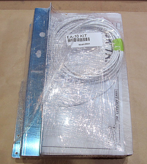
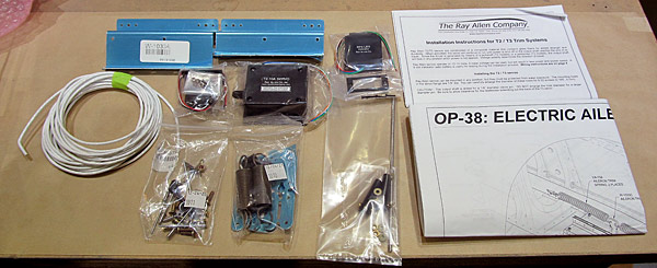
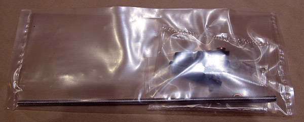
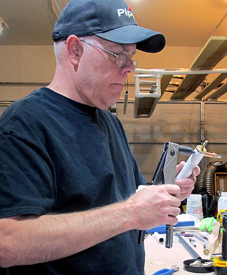
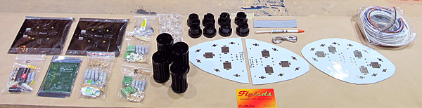
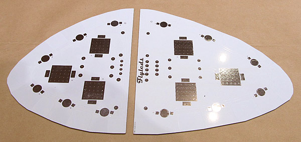
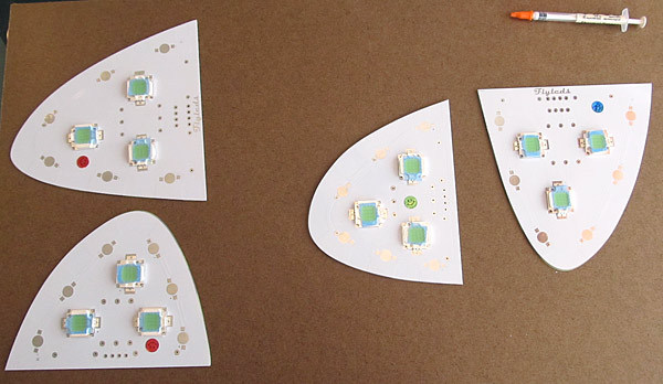
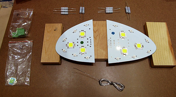
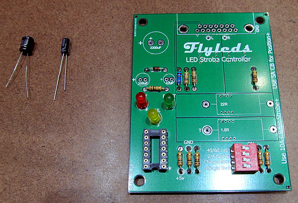
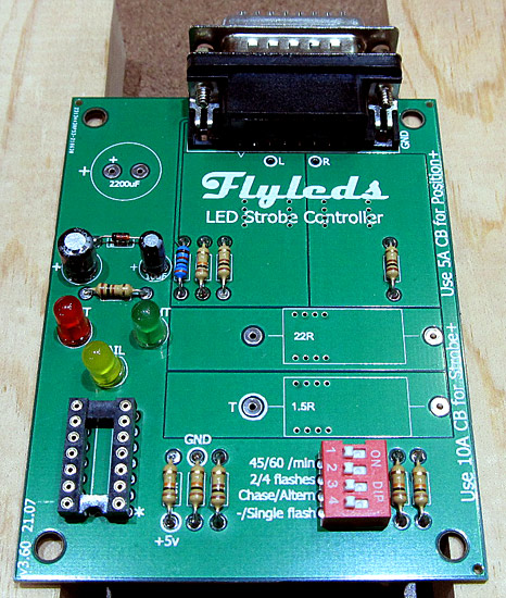
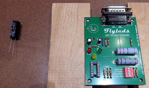
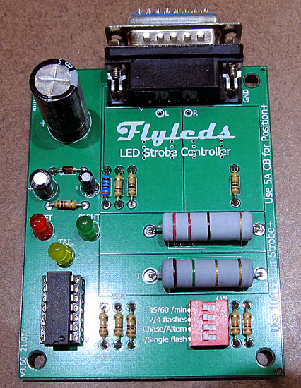
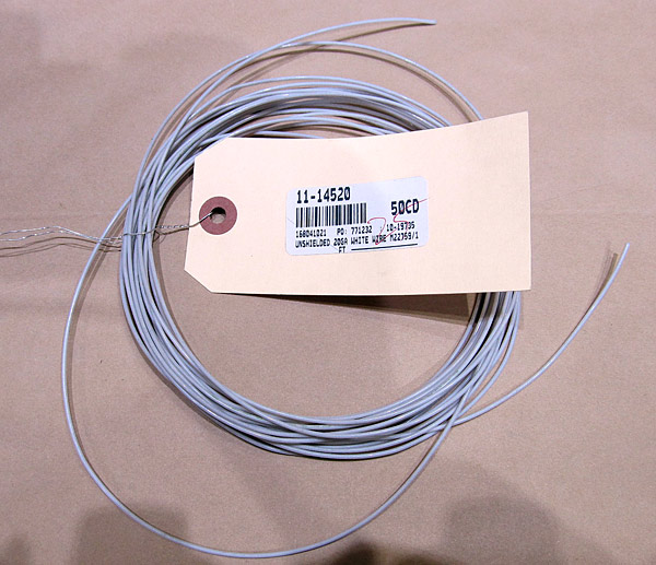
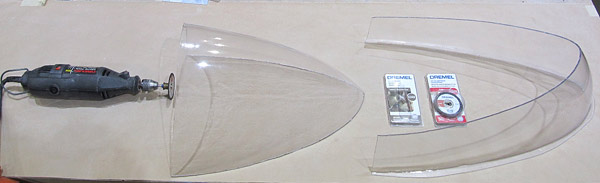
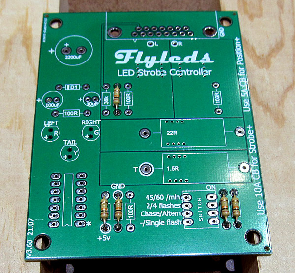
While I am waiting for the milspec 20 gauge wire to arrive, I began the process of building the strobe LED controller board.

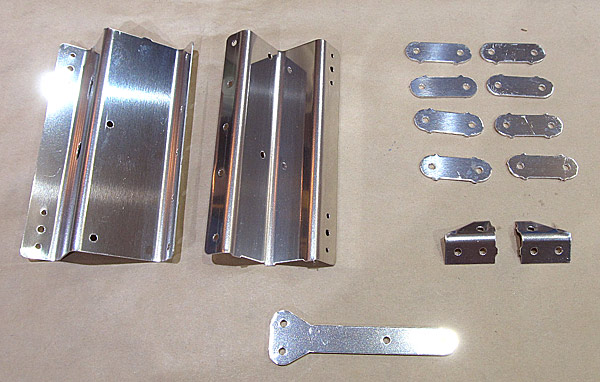
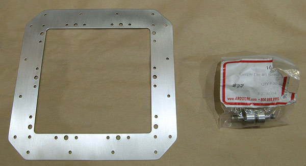
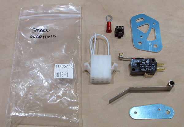
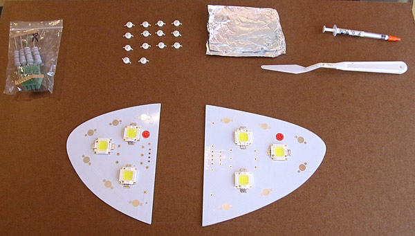
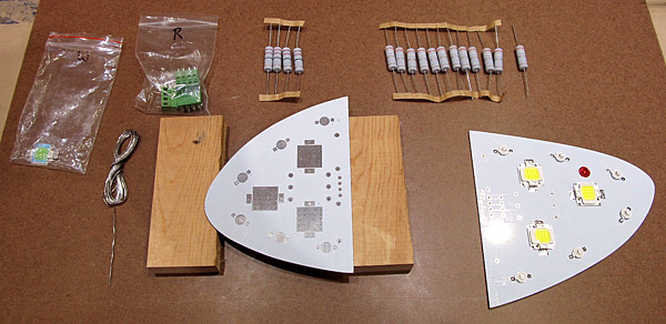
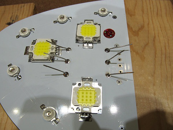
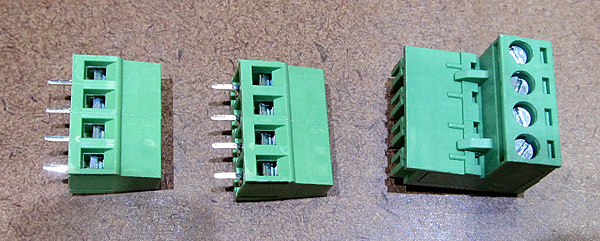
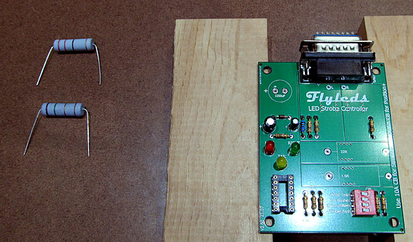
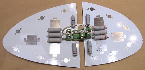
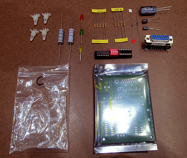
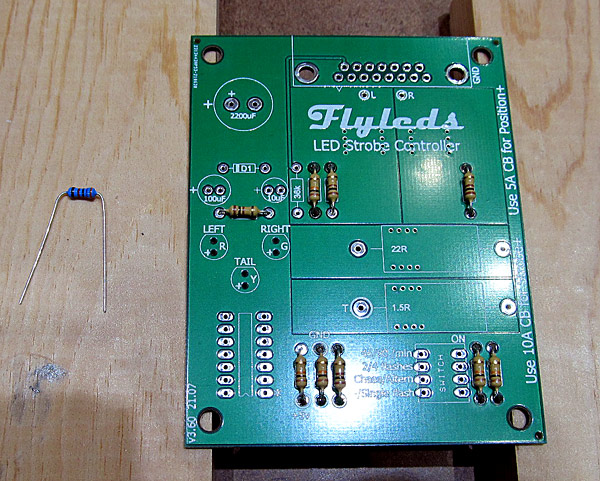
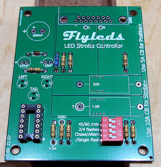
These are all of the components that will be needed to construct it.

Preparing the 10Ω Resistors

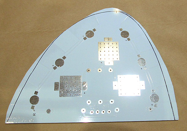
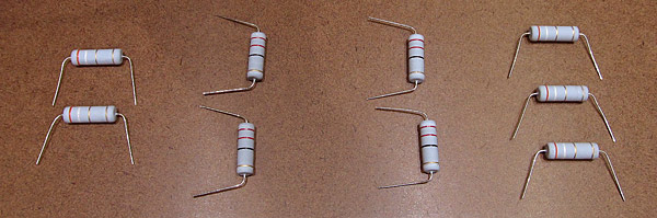
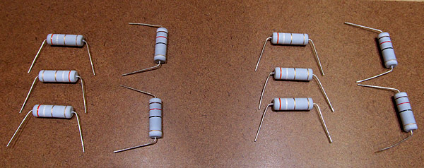
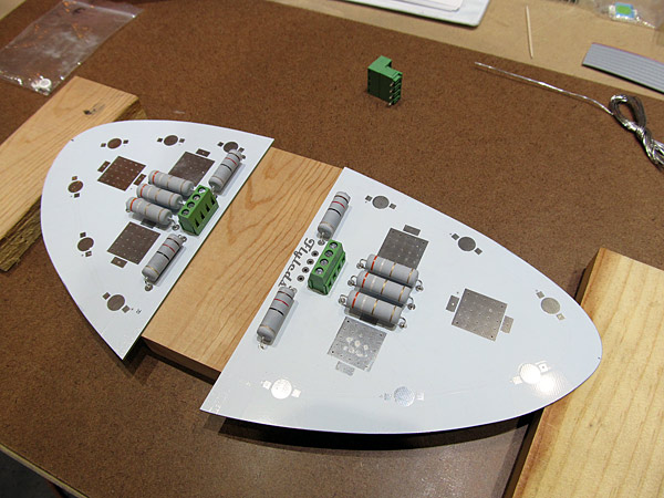
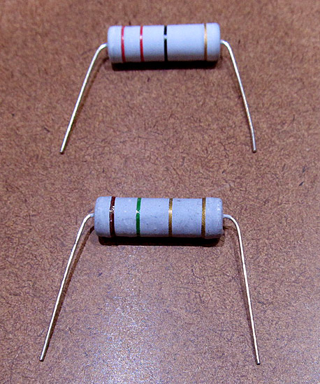
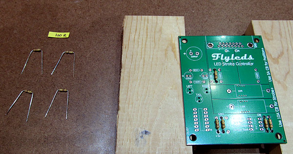
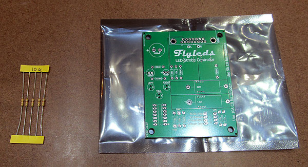
There are five 10Ω resistors that need to be prepared and installed onto the controller board first.

Bend Resistor Legs

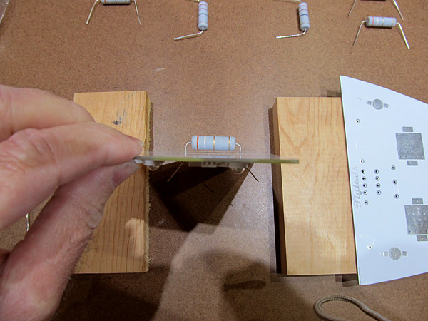
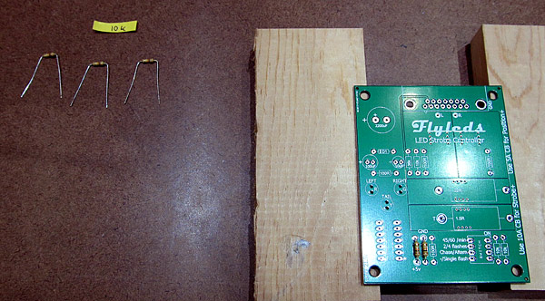
As per step one, on page two of the instructions, the legs on each of the five 10Ω ohm (brown-black-orange-gold) resistors need to have the legs (or leads) bent first and then installed onto the controller board.

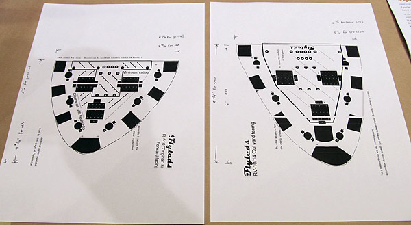
*The controller board is well marked as to where each component goes, but there is also a great diagram on page one of the instructions that also gives a reference too.

10&0hm; Resistors Soldered In Place

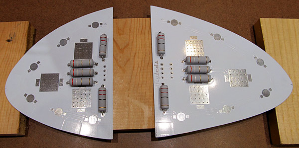
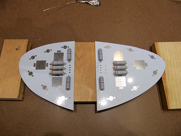
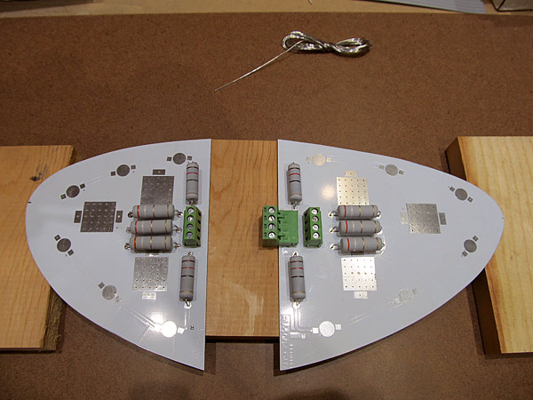
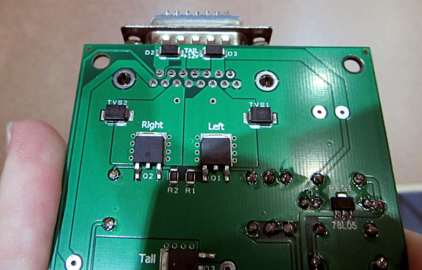
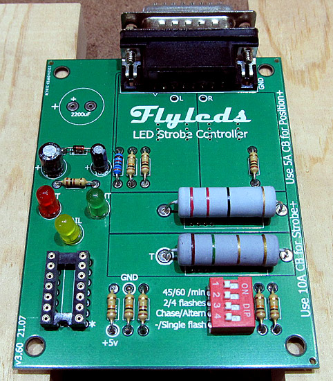
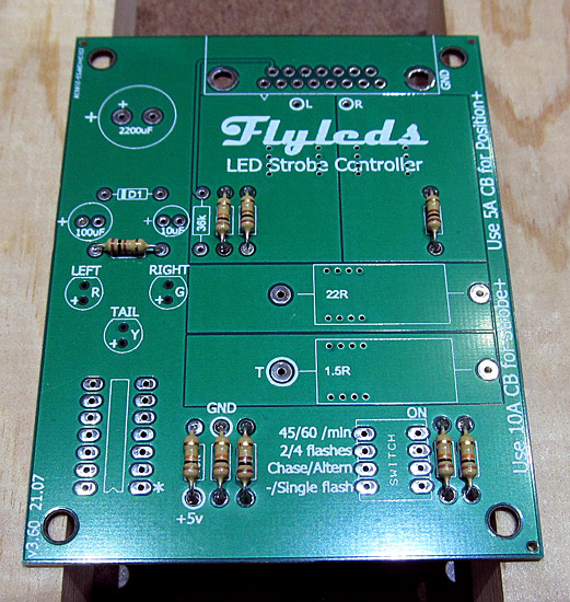
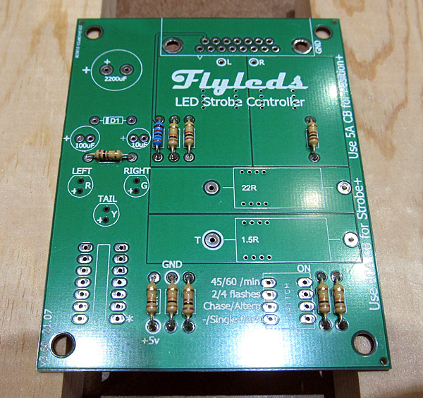
This shows all five of the 10Ω ohm resistors in the proper location and they have all been soldered.

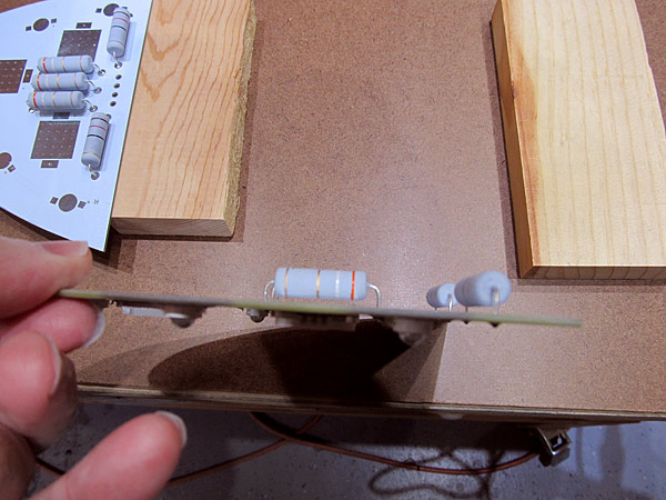
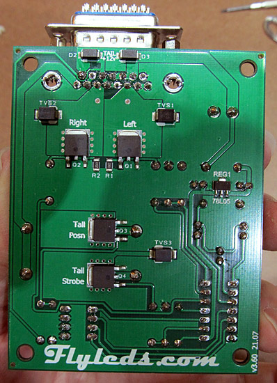
I like to trim the excess lead (leg) material off on the back of the controller board after soldering the components in.

100Ω Preparation

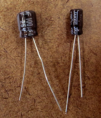
There are four 100Ω (brown-black-brown-gold) resistors that need to be prepared for installation next.

The legs are bent as before, and the resistors are placed onto the labeled locations on the controller board.

100Ω Resistors Soldered

The 100Ω ohm resistors have been soldered in place and the excess lead (leg) material trimmed off.

Prepare 36Ω Resistor

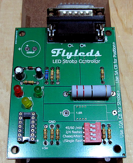
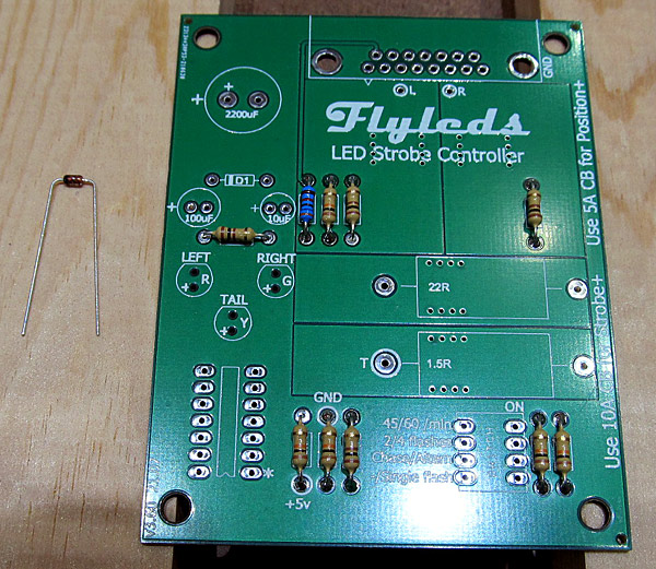
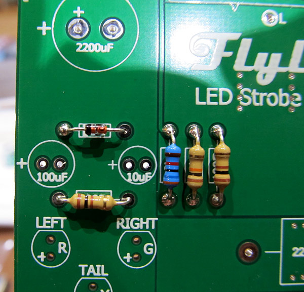
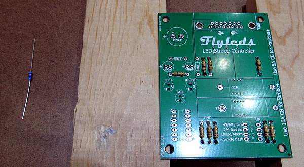
There is one 36Ω (orange-blue-black-red-brown, blue body) resistor that needs to be prepared for installation next.

36Ω Resistor Installed

The leads (legs) of the 36Ω ohm resistor are bent before the resistor is inserted into it's proper place on the controller board.

36&0hm; Resistor Soldered

The 36Ω ohm resistor has been installed and soldered in place and the excess lead (leg) material has been trimmed off the back of the circuit board.

1N4148 Diode

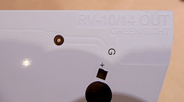
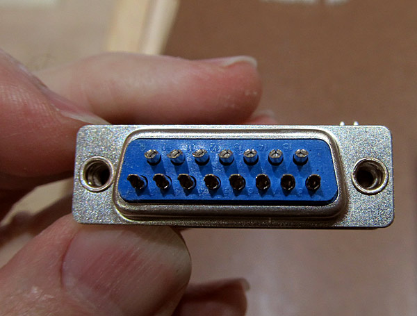
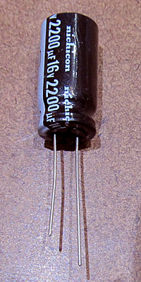
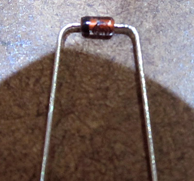
There is a diode that needs to be installed onto the controller board next.

This is what it looks like.

*It's important to note that the diode has a black band around one end....orientation will be important when installing this onto the controller board.

1N4148 Diode Prepared For Installation

Just like before, the leads (legs) of the 1N4148 diode are bent before being inserted onto the controller board.

*The 1N4148 will be installed where the circuit board is marked D1 in this photograph.

The black band should be facing towards the left.

1N4148 Diode Soldered

This photograph shows the 1N4148 diode installed in the D1 position and it has been soldered into place. The excess lead (leg) material on the back of the circuit board has been trimmed off.

IC Socket

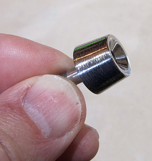
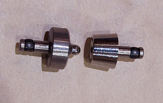
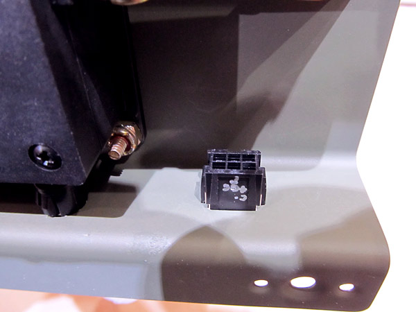
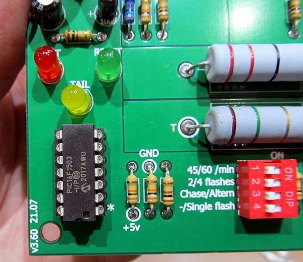
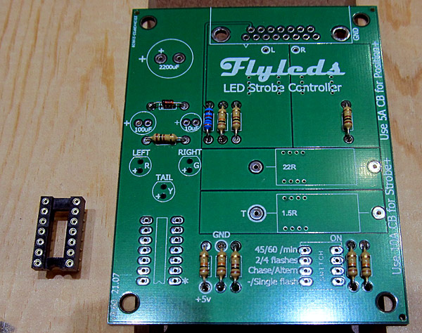
The IC socket for the microcontroller is to be installed next.

The IC socket is shown on the left in this photograph.

*Make sure to note that there is a "notch" on one end of the IC socket, it will need to be mounted aligned with the * marked on the controller board....basically it faces "south".

Each of the silver "circles" on the IC socket has a corresponding pin that will need to be soldered on the back of the board.

IC Socket Soldered

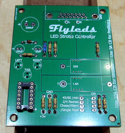
Here is a closer look at the IC socket that has been soldered into place on the controller board.

*Make sure when soldering that the IC socket sits flush to the controller board.

Four-Way DIP Switch

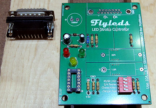
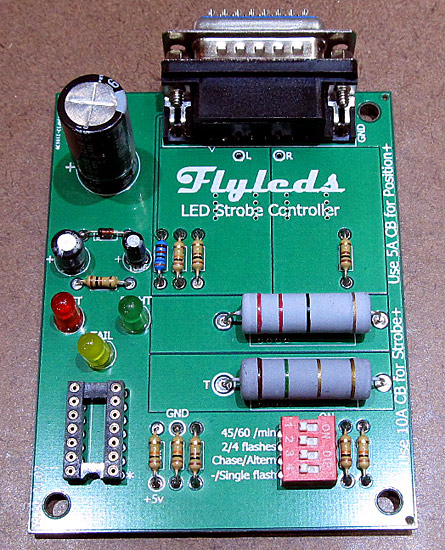
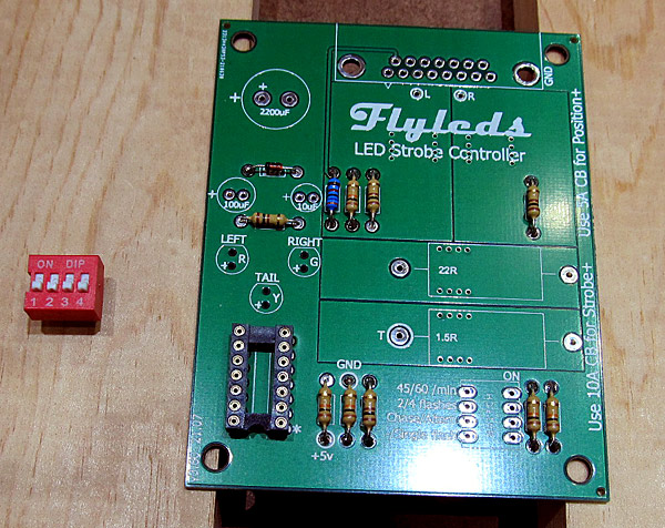
A red four-way DIP switch is to be installed next onto the controller board.

*Make sure to reference the diagram and photograph on page one of the instructions because orientation is important when mounting this component.

Four-Way DIP Switch Soldered

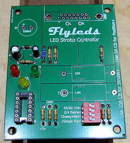
The red four-way DIP switch was soldered into it's correct position onto the controller board.

3 Colored LED Lights Prepared

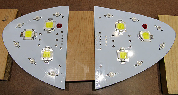
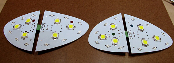
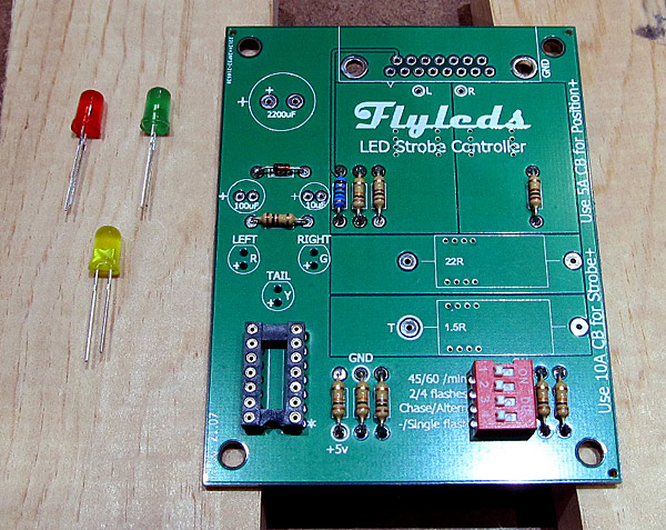
There are three colored LED lights that need to be installed next, a red LED, a green LED, and a yellow LED.

*Make sure to take note that each LED light has a longer leg.

The longer leg of each LED mounts in the hole closest to the IC socket.

Long Leg On One Side Of LED Light

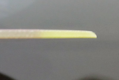
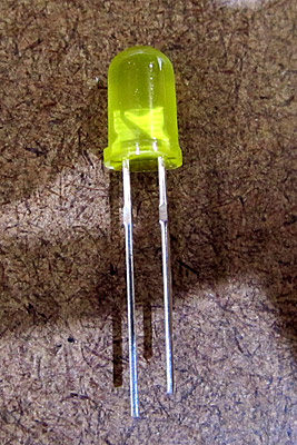
Here is a closer look at the LED light showing that one of the leads (leg) is longer.

*The long lead (leg) is the + positive side.

LED Lights Soldered To Controller Board

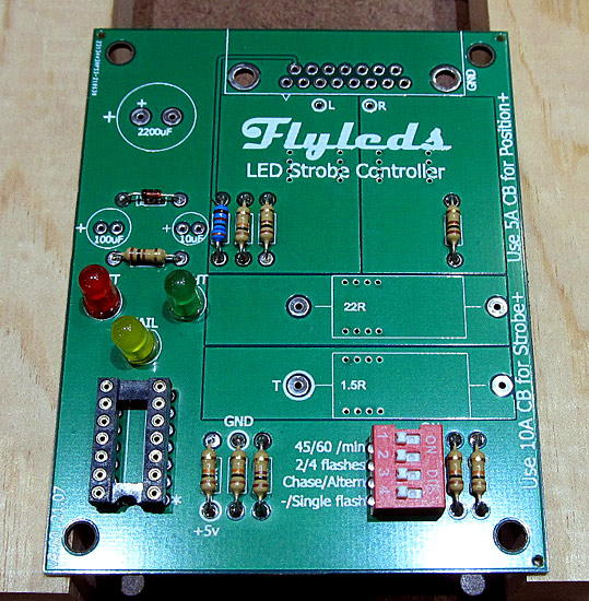
The three LED's were soldered to the controller board and the excess lead (leg) material on the back of the circuit board was trimmed off.
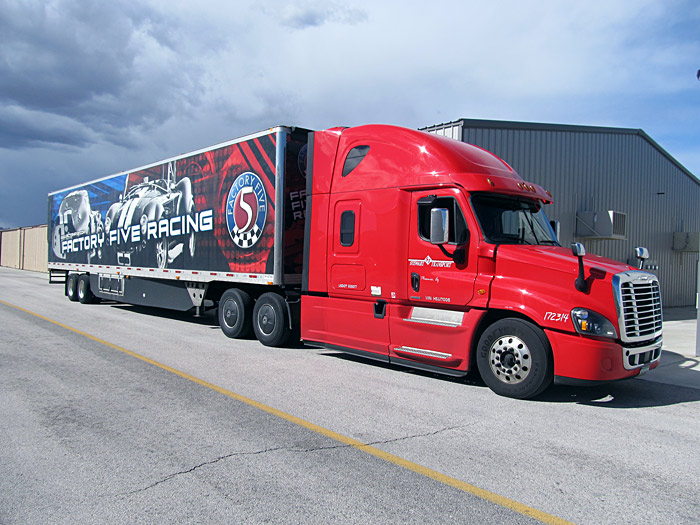
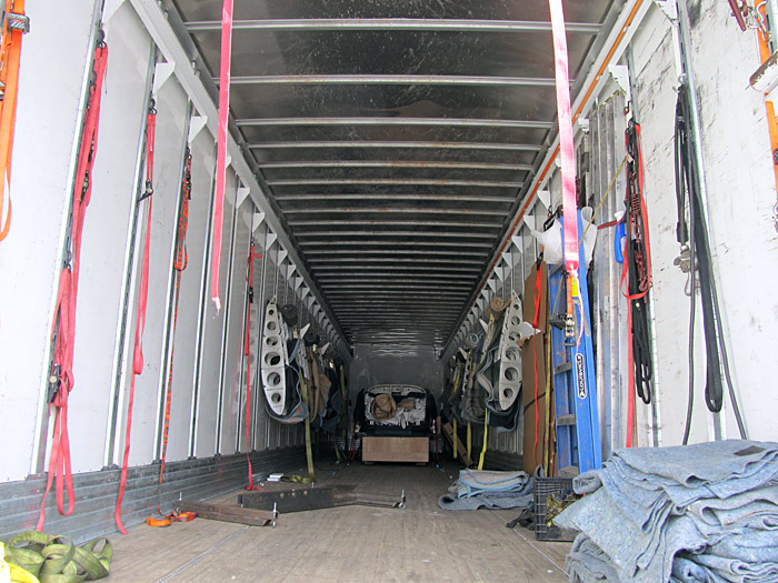
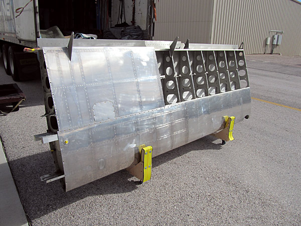
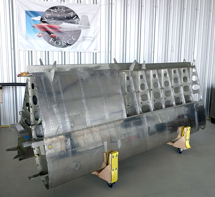
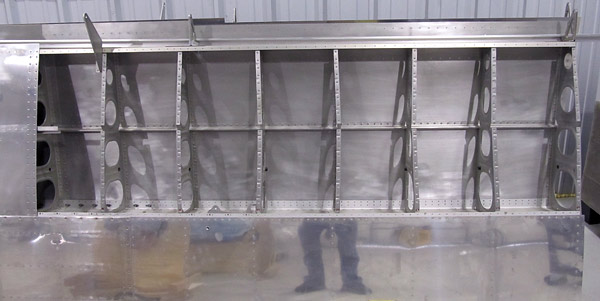

Controller Board Capacitors

Two small capacitors are to be installed on the controller board next.
One capacitor is a 100㎌ microfarad capacitor and the other is a 10㎌ microfarad capacitor.
*These two capacitors are shown on the left of this photograph.

Page one in the instructions shows that these two capacitors will be installed just above the three LED lights. In addition, the controller board is silk-screened with "circles" where they are to be mounted.

*Be careful to note the orientation of these capacitors.
There is a + side to each capacitor.

Controller Board Capacitors

Here is a closer view of the (100㎌ and 10㎌) microfarad capacitors.

The longer lead (leg) of each capacitor is the + terminal and it must be mounted so it matches the + silk-screened on the controller board.

*Additionally, the larger 100㎌ capacitor will be mounted to the left of the smaller 10㎌ capacitor.

Capacitors Soldered Inot Place

The 100㎌ and 10㎌ capacitors were soldered to the controller board and the excess lead (leg) material was trimmed at the back of the controller board.

15 Pin D Connector

The 15 pin D connector is installed next.

It gets mounted at the top of the controller board.

15 Pin Male D Plug

This is what the front of the 15 pin male D plug looks like.

15 Pin Male D Plug

All of the 15 pins need to be carefully pushed in place onto the controller board.

15 Pin Male D Plug

The 15 pin male D plug was soldered onto the controller board.

15 Pin Female D Socket Secured

The 15 pin female D socket was secured to the D connector.

Ceramic Power Resistors

Two large ceramic power resistors will be mounted next.

One power resistor is a 22Ω (red-red-black-gold ohm resistor, the other is a 1.5Ω (brown-green-gold-gold) ohm resistor.

*Just like all of the other components, the leads (legs) need to be bent before installing the resistor to the controller board.

Ceramic Power Resistor Location On Controller Board

The 22Ω and 1.5Ω power resistors will be installed just above the red, four-way DIP switch.

22Ω Power Resistor Soldered

The 22Ω ohm power resistor was soldered onto the contoller board and the excess lead (leg) material was trimmed off on the back of the board.

*Make sure to leave a millimeter or so air gap between the resistor and the circuit board for heat dissipation when mounting the resistor in place.

1.5Ω Power Resistor Soldered

The 1.5Ω ohm power resistor was soldered onto the contoller board and the excess lead (leg) material was trimmed off on the back of the board.

*Make sure to leave a millimeter or so air gap between the resistor and the circuit board for heat dissipation when mounting the resistor in place.

2200㎌ Capacitor

One more capacitor to be installed next, this is a big one...

This is the 2200㎌ microfarad capacitor.
The longer leg of this capacitor is the + terminal so make sure to orient it properly onto the controller board.

Position The 2200㎌ Capacitor

The 2200㎌ capacitor is to be installed just to the left of the 15 pin D connector.

*Double check to make sure that the longer + terminal of the capacitor is oriented to the + side of the circuit board.

2200㎌ Capacitor Soldered

The 2200㎌ capacitor was soldered onto the controller board and the excess lead (leg) material was trimmed off of the back of the board.

Clean The Back Of The Circuit Board

I cleaned the back of the controller circuit board with 91% isopropyl alcohol.

Microcontroller Chip Installation

The PIC16F1503 microcontroller chip needs to be installed onto the IC socket.

*Some of the legs of the microcontroller chip may need to be adjusted so that it will fit straight into the IC socket.
If so, just hold one side of the microcontroller chip against the workbench and gently roll the entire chip so that the legs bend almost 90° to the body of the chip then flip the microcontroller chip over and do the same thing to the other side.

The PIC16F1503 microcontroller chip should then fit into the IC socket.

Microcontroller Chip Installed

This is what the PIC16F1503 micrcontroller chip looks like when it is installed.
This chip is held in place by friction and is NOT soldered in place.

*Make sure that the small detent/notch in the microcontroller chip corresponds with the * on the controller circuit board.

Online Lay Out Cut-outs Plans For Navigation Lights In Wingtip

The wingtip bays need to have portions cut-out so that the navigation/strobe light circuit boards containing power resistors and power connections can sit flat against the surfaces when mounted.

There are suggested cut-out templates available online at the Flyleds website.

*Make sure you check that your printer printed the templates to scale and that the size is correct....don't want to cut out too much or too little material on those expensive wingtips!

Lay Out Cut-outs For Navigation Lights In Wingtip

I transfered the template cut-out onto a piece of masking paper and then taped it onto the wingtip in order to draw some cutout lines.

This is the left/port wingtip.

Lay Out Cut-outs For Navigation Lights In Wingtip

This is the right/starboard wingtip.

Lay Out Cut-outs For Navigation Lights In Wingtip

These are the cut-out lines for the left/port wingtip.

*To make the cuts simpler, I decided to draw diagonal lines to connect the top of the "notch" to the main body line.
You will see this in the following photographs.

Lay Out Cut-outs For Navigation Lights In Wingtip

These are the cut-out lines for the right/starboard wingtip.

*To make the cuts simpler, I decided to draw diagonal lines to connect the top of the "notch" to the main body line.
You will see this in the following photographs.


Wingtip Cut-outs

After the lay out lines were finalized, I started the process of cutting excess material from thr wingtip navigation/strobe light coves.

I first used a drill to establish "rounded corners" at all of the cut-out intersections. This will make it easier when I use a dremel tool with a cut-out wheel to cut the straight portions being able to land on a hole and not have any over-cut.

This is the right/starboard (W-1015-R) wingtip.

Wingtip Cut-outs

This is the left/port (W-1015-L) wingtip.

Wingtip Cut-outs

I used a Dremel with a small 15/16" (part number 409) cut-off wheel to make the straight cuts.
I cut just inside of the line and will "final dress" the cut with a small file.

Wingtip Cut-outs

This is the right/starboard (W-1015-R) wingtip after the cut-out has been trimmed to the lay out line with a small file.

Wingtip Cut-outs

The excess material was cut out on the red/port (W-1015-L) wingtip.
Final trimming to go...


Wingtip Cut-out

This is the left/port (W-1015-L) wingtip after the cut-out has been trimmed to the lay out line with a small file.

Wiring Nav/strobe Circuit Boards Together

The unshielded, milspec, 20 gauge wire that ordered finally arrived so I want to join the navigation/strobe light circuit boards together next.

Wire Cut To length

Eight, five inch pieces of the 20 gauge wire were cut and the ends stripped 1/4".

Labeled Wires

The ribbon cable at the top of the photograph is what is supplied with the navigation/strobe light kit from Flyleds. I wanted just a little more length on the wires and also wanted to label them so that I could identify them if ever I needed to in the future, so I labeled them in pairs.

*There are four wires needed to join the navigation/strobe light circuit boards.

Starboard Navigation/Strobe Lights Wired

This is the left/port navigation/strobe light circuit boards wired together.

Starboard Wingtip

This is the left/port wingtip with the navigation/strobe circuit boards wired together setting in place.

Port Navigation/Strobe Lights Wired

This is the right/starboard navigation/strobe circuit boards wired together.

Port Wingtip

This is the right/starboard wingtip with the navigation/strobe circuit boards wired together setting in place.

Testing Strobe Lights

I tested the strobe lights using a 9 volt transistor battery by attaching two lead wires from the battery to the green terminal blocks on the back of the joined circuit boards.

It was bright, with just a 9 volt battery, I imagine these will REALLY be bright when hooked up to a 12 volt battery!

Testing Position Lights

I tested the red position lights using a 9 volt transistor battery by attaching two lead wires from the battery to the green terminal blocks on the back of the joined circuit boards.

*Be careful to heed the warning, on page seven of the instructions, not to individually test the smaller position LED lights because they will not be able to handle the power!

Testing Position Lights

Here is what it looks like in the dark!

Testing Position Lights

I tested the green position lights using a 9 volt transistor battery by attaching two lead wires from the battery to the green terminal blocks on the back of the joined circuit boards.

*Be careful to heed the warning, on page seven of the instructions, not to individually test the smaller position LED lights because they will not be able to handle the power!


Squaring Lens Recesses

As per step one, on page 24-03 of the builder's manual, the (W-1015-L and W-1015-R) wingtip lens recess edges and corners need to be squared.

*You can see in this photograph that the inside recessed area of the wingtip is rounded and the (VA-193) lenses need a better, flatter, surface to sit on.

File

I used a small file to square the edges.

Squaring Lens Recesses

I started the process at the top of the (W-1015-L) left wingtip.

It is a slow tedious process but you have to go around the entire inner surface of the lens recess area with the file work. Additionally, there are seams that, due to the manufacturing process of the wingtips, will have to be flattened.

Wingtip Seams

This is a better view of the seams that I was referring to. They go the entire length of each wingtip.

Squaring Lens Recess

I am done squaring the lens recess of the (W-1015-L) left wingtip.


Cut VA-193 Lens Cover

As per step two, on page 24-03 of the builder's manual, the (VA-193) wingtip lens needs to be cut in half.

Before I started to cut the (VA-193) lens in half I wanted to verify that the score line that is on the lens is really the half way point.
It's close but not truly on center, but don't worry, there is plenty of material left over so I cut the lenses in half using the score line as a reference.

Cut VA-193 Lens Cover

I used a Dremel with a small 15/16" cut-off wheel (part number 409) to make the cut.

Cut VA-193 Lens Cover

Now there are two lenses, (VA-193-L and VA-193-R).


Squaring Lens Recess

As per step one, on page 24-03 of the builder's manual, the (W-1015-L and W-1015-R) wingtip lens recess edges and corners need to be squared.

*You can see in this photograph that the inside recessed area of the wingtip is rounded and the (VA-193) lenses need a better, flatter, surface to sit on.

As was done on the left wingtip, I started the process at the top of the (W-1015-R) right wingtip.
The seams that, due to the manufacturing process of the wingtips, will have to be flattened on this wingtip too.

Wingtip Seams

This is a better view of the seams that I was referring to. They go the entire length of each wingtip.


Squaring Lens Recess

Here is a closer view of the squaring process being done on the (W-1015-R) right wingtip.

My main focus at this point is to get the inside edges of the recesses squared but I will come back later and take care of the seams that exist on these wingtips, especially in the cove areas, where the navigation/strobe light circuit boards sit because they need to be able to sit flush against the faces of the wingtip.

Squaring Lens Recess

This view is near the leading edge of the (W-1015-R) wingtip.

Squaring Lens Recess

I finished the squaring of the inner recesses and corners of the (W-1015-R) right wingtip.


Sanding Wingtip Seams

Now it is time to address the seams that exist in the wingtip navigation/strobe recesses.
As I said before these seams need to be sanded smooth so that the navigation/strobe circuit boards will sit flush against the wingtip faces.

The fiberglass is hard so I started out with 150 grit sandpaper, then 220 grit, and finished off with 320 grit.

Sanding Wingtip Seams

This is what I want, a nice flat surface!

Sanding Wingtip Seams

Nice!

Sanding Wingtip Seams

The (W-1015-R) right wingtip recess area seams have been flattened, the left wingtip is next.


Sanding Wingtip Seams

Okay, now it is time to address the seams that exist in the left wingtip navigation/strobe recesses.
As I said before these seams need to be sanded smooth so that the navigation/strobe circuit boards will sit flush against the wingtip faces.

Just like before, I started out with 150 grit sandpaper, then 220 grit, and finished off with 320 grit.

Sanding Wingtip Seams

The seams stand proud of the faces at least 1/16", just enough not to allow the circuit boards to sit flush.

Sanding Wingtip Seams

Alright, just what I'm looking for!

Sanding Wingtip Seams

Nice!


Fill Voids In Wingtip With Epoxy

There are small pinholes and scratches in the wingtips that need to be filled with epoxy resin filler.

*Make sure that you reference the builder's manual section 5.18, page 05-16 when choosing what filler to use.
Some parts will tolerate polyester resins and some don't, but epoxy resin is okay to use on either polyester or epoxy parts.
I am going to use West Systems epoxy two part resin in working with the fiberglass parts.

Fill Voids In Wingtip With Epoxy

I will fill all of these seams too, and eventually fill the seams along the entire side of the wingtips.

West System Epoxy

It's still a little cold in the shop but doesn't get below 40°F at night here and is usually in the low 60°F's during the daytime so I chose to fill these voids with West Systems (105 resin, 206 hardener, and 410 microlight fairing filler).
The (206) hardener is a fast cure hardener and can be applied in as low as 40°F, but since it will be 61°F when I apply it there shouldn't be any problems.
The (410) microlight fairing filler is used to "thicken" the mixture and help contour any uneven areas.

Left Wingtip Epoxied

I applied the epoxy resin/filler mixture to the left wingtip first, smoothing it out somewhat with a plastic body filler applicator.

Right Wingtip Epoxied

The right wingtip was next, you don't have a lot of time to spread the filler but I was able to do these two wingtip areas in about 20 minutes....just about the maximum "pot life".


Sanding Wingtips

Okay, from here on out there is going to be a lot of sanding. I am using 320 grit sandpaper; I don't want a bunch of deep scratches in the fiberglass and so it will probably take a little longer to do the job but "it is what it is"....

I'm starting the work on the (W-1015-L) left wingtip first.

Sanding Wingtips

I have the surface flat and smooth, I'll probably put a clear, purely epoxy resin/hardener coat on later to seal any of the pinholes that will be revealed.


Sanding Wingtips

The (W-1015-R) right wingtip is next, still using 320 grit sandpaper.

*Make sure to use a sanding block, you don't want any waves to show up after all that work sanding!

Sanding Wingtips

The seams that run the entire length of the wingtip will eventually need to be smoothed out so I started working on them at this time too.

*I forgot to mention it but make sure that you use a good respirator when doing this sanding, dust is everywhere and you sure don't want to be breathing it all in!


Sanding Wingtips

I mixed up a batch of West Systems epoxy 105 resin, 205 hardener, and 410 microlight fairing filler and applied it along the length of the seams on the (W-1015-R) right wingtip.

Sanding Wingtips

I started to smooth out the long seam on the (W-1015-L) left wingtip.


Sanding Wingtips

It took a while, but the standing seam along the length of the (W-1015-L) left wingtip has been flattened, and is ready to have epoxy filler applied.

Sanding Wingtips

Just another view of the (W-1015-L) left wingtip.


Sanding Wingtips

Let the epoxy filler application begin!

Sanding Wingtips

I mixed up a batch of West Systems epoxy 105 resin, 205 hardener, and 410 microlight fairing filler and applied it along the length of the seams on the (W-1015-L) left wingtip.

Sanding Wingtips

I began sanding the epoxy filler that was applied earlier to the (W-1015-R) right wingtip.

It is really important to use a long sanding block to keep the edges straight when sanding this seam because it is too easy to get waves with a span this long.

Sanding Wingtips

It's slow going, don't forget to "feather" the edges!


Sanding Wingtips

I started placing some blue painter's tape along the edges of where I am sanding. It's too easy to get unwanted scratches on the wingtip where you don't want them when using the longer sanding block.

I am using a 12" sanding block for this part of the project.


Sanding Wingtips

I finished sanding the epoxy filler on the (W-1015-R) right wingtip but there are some low spots that will have to have additional filler applied.

Sanding Wingtips

I taped the area around the edges before I applied additional filler to the seams, I don't want to get any extra filler where I don't need it to be.

Sanding Wingtips

I mixed up a batch of West Systems epoxy 105 resin, 205 hardener, and 410 microlight fairing filler and applied it along the length of the seams on the (W-1015-R) right wingtip.
I put a thicker amount in the few low spots that I saw.

*The epoxy filler mixture is about the thickness just shy of peanut butter but I might thicken it up slighlty in the next application, it's still too thin because it sags somewhat during the curing process.

Sanding Wingtips

I started to sand the epoxy filler that I applied earlier on the (W-1015-L) left wingtip.


Sanding Wingtips

I finished sanding the seams on the (W-1015-L) left wingtip.

There a few low spots on this wing tip that need filled again.

Sanding Wingtips

Just another side view of the (W-1015-L) left wingtip.

Sanding Wingtips

Here's the other side view, same (W-1015-L) left wingtip.

Sanding Wingtips

I mixed up a batch of West Systems epoxy 105 resin, 205 hardener, and 410 microlight fairing filler and applied it along the length of the seams on the (W-1015-L) left wingtip.
I put a thicker amount in the few low spots that I saw.

Sanding Wingtips

I thickened the epoxy mixture some but it is still sagging a bit, I'm going to have to thicken it just a little bit more....maybe go for "chunky" peanut butter next time, haha!


Wingtip Sanding

Sanded the (W-1015-L) left wingtip West Systems epoxy filler with 320 grit sandpaper.

There is a lot of work to get these wingtips to where they are ready for painting, preparation is key so sand, fill, sand....


Sanding Wingtips

Finished sanding the Wesy Systems epoxy filler that was applied to the (W-1015-L) left wingtip.

Sanding Wingtips

Here is another side view.

Wingtip Pinholes

As you can see by this close up, there are tiny pinholes that will need to be filled in.
There are a few more low spots that will need to be filled as well.

*The low spots will be filled in first with the West Systems epoxy 105 resin, 205 hardener, and 410 microlight fairing filler mixture, but the pinholes will be filled in with just the pure resin/hardener mix.


Wingtip Preparation

These are the low spots on the (W-1015-L) left wingtip that were filled with the West Systems epoxy 105 resin, 205 hardener, and 410 microlight fairing filler mixture.

Wingtip Preparation

Just a bit of filler on the trailing edge...


Sanding Wingtip

I finished sanding out the low spots that were filled with the West Systems filler on the (W-1015-L) wingtip.

Next, it's time to deal with the pinholes.

Wingtip Pinholes

In order to address the pinholes that need to be filled, I first cleaned off the wingtip with 91% isopropyl alcohol and then using the compressor, blew out all of the dust with pressurized air.

Wingtip Pinhole Treatment

The temperatures are getting warm where I am and are consistently in the 65°- 75°F range so I am going to switch to the West Systems 206 slow cure hardener.
It will give me a little bit more work time, but not much more. (20-25 minutes @ 72°F pot life.)

The procedure that I will use to fill the pinholes is to apply the epoxy resin with the paint "chip" brushes and then squeegee the excess off with an autobody "bondo" spreader and then wait about 40 minutes, or until the epoxy resin gets tacky (like masking tape), and then apply an additional epoxy resin coat, squeegee that coat off and then wait an additional 40 minutes or so and then apply another coat of epoxy resin...you get the idea right?
The point is to apply enough coats to fill the pinholes.

*The "chip" paint brushes worked okay, but for the next wingtip I am going to use an epoxy resin roller brush because the paint brushes occasionally leave a stray bristle in the epoxy and it isn't fun to pick them out of the resin especially when you only have a 20-25 minute pot life to deal with.

Squeegee Excess Epoxy Resin Off

Here I am squeegeeing off the excess epoxy resin with the "bondo" autobody filler spreader.

Epoxy Resin Coat One

Here are the pinholes after one epoxy resin fill.

I eventually applied four coats.

Epoxy Resin Coat

As you can see the epoxy resin looks shiny when it is applied.

Epoxy Resin Coat

Here is another view.

Epoxy Resin Coat

This is a close up view of the pinholes after the second coat of epoxy resin was applied.

Epoxy Resin Coat

This is a close up view of the pinholes after four coats of epoxy resin were applied.

Epoxy Resin Coat

This is a view of the entire length of the (W-1015-L) left wingtip after four coats of epoxy resin were applied.

Now, just sit the wingtip aside and wait for the epoxy resin to fully cure.
West Systems recommends four days.


Sanding Wingtips

Time to start sanding the epoxy filler applied to the (W-1015-R) right wingtip...


Sanding W-1015-R

As you can see from these photographs, I like to put masking tape just below where I am going to sand so that I don't inadvertently sand too far into the thin top coat of the wingtip.

This is the (W-1015-R) right wingtip; I am sanding it with 320 grit sandpaper to sand the West Systems epoxy filler applied earlier.


Sanded W-1015-R

I finished sanding the (W-1015-R) right wingtip with 320 grit sandpaper but there are still some low spots and pinholes that I still need to address.

Epoxy Fill Low Spots

The arrows point to some of the low spots and the pinholes that I need to fill with more epoxy filler.

Epoxy Fill Pinholes

Some low spots here.

Epoxy Fill Low Spots

Sand fill, sand fill...


Epoxy Fill Low Spots

After the surface of the (W-1015-R) right wingtip has been cleaned off with 91% isopropyl alcohol and blown dry with compressed air you can really see the places that still need more epoxy filler.

Epoxy Fill Low Spots

It's a process...haha!

Epoxy Filled Low Spots

I put the epoxy filler on a little thicker this time.

Epoxy Filled Low Spots

I'll start sanding again after a few days.


Sanded W-1015-R

Okay, it's been a few days and I have finished sanding the (W-1015-R) right wingtip with 320 grit sandpaper and now I am ready to put a clear coat of epoxy filler on to fill in some of the small pinholes that are still there, (there are fewer of them thankfully).


Pinholes Need Seal Epoxy Coat

Today I will be applying just a West Systems epoxy 105 resin and 206 hardener mixture with the idea of putting enough "skim" coats of filler on to fill the pinholes.

Instead of using "chip" brushes to apply the epoxy to the (W-1015-R) right wingtip, I am going to use a paint roller to apply the epoxy.

W-1015-R Epoxy Seal Coat

I cleaned off the surfaces of the (W-1015-R) right wingtip with 91% isopropyl alcohol and then blew off everything with compressed air. I also taped along the edges of where I was going to apply the clear epoxy mixture so that I didn't get any epoxy running down the sides of the wingtip.

The procedure is pretty much the same as before when I applied the clear coat of epoxy resin to the (W-1015-L) left wingtip: apply epoxy filler on then squeegee the excess off with a Bondo autobody spreader, wait until the surface gets tacky then apply another epoxy coat and squeegee the excess off and repeat the process as necessary to fill the pinholes.

*I used four coats of epoxy filler on the (W-1015-L) left wingtip, hopefully that will be enough for this wingtip.

Roller Brush Applicator

This is the paint roller and microfiber roller brush that I am going to use to apply the epoxy filler to the wingtip with.

Roller Microfiber Brush

These are the rollers that I used, there are two to a pack.

First Clear Epoxy Coat

This is what the first coat looks like after application, it's pretty shiny but it will dull some as it drys.

Clear Epoxy Coat Applied

There are four coats of the epoxy resin filler applied to the (W-1015-R) wingtip.

Overall, I liked using the microfiber roller system of applying the clear epoxy filler but it does tend to use up more resin than when you brush the epoxy on. As far as costs go, I imagine if you are going to use a brush it is best to stay away from the "chip" brushes because of the bristles coming loose and contaminating the surface so a more expensive brush would probably be about the same as the microfiber rollers are.

Later on, after I sanded the clear coat epoxy layers, I found that I should have put on a couple more coats on this right wingtip, it just had more pinholes than the left one did....


Sanding Clear Epoxy Coat On Wingtips

I used 600 grit sandpaper to sand this final clear coat West System epoxy fill applied to the wingtips.


Sanding Clear Epoxy Coat On Wingtips

The (W-1015-L) left wingtip is next...


Sanding Clear Epoxy Coat On Wingtips

I'm hoping that by using 600 grit sandpaper on the final clear epoxy coat it will provide a nice base for when I apply the epoxy primer paint later on.


Sanding Clear Epoxy Coat On W-1015-L

Looks good, there are a few small touch up fills that need to be done though...


Wing Tip Preparation

The wing tips were cleaned with 91% isopropyl alcohol in preparation to fill low spots with West System epoxy filler.

There are three spots on the (W-1015-R) right wing tip and the (W-1015-L) left wing tip needs a light "skim coat".

Wing Tip Preparation

I like to mask off around the working area of the wing tip before I apply the West System epoxy filler so that I don't get any drips onto the surfaces under the work area.

This is the (W-1015-L) left wing tip which will receive the "skim coat" of West System 105 resin and 206 hardener applied with a microfiber roller brush.

Wing Tip Preparation

The "skim coat" once applied is shiny and should do a good job of filling the remaining pinholes.

*There were several days which I sanded, refilled, and sanded again but I am not going to show them again....by now you get the idea, lots of preparation before any painting can be done!


Fitting Nav Lights

It's time to secure the navigation light circuit boards to the wing tips.

Flyleds recommends using double sided tape to secure the boards to the navigation "coves or bays" but I don't want to depend on the tape so I am planning on using screws to secure the boards in place.

Nav Light Drill Templates

There are templates that you can download and print available from the Flyleds website that show where you can safely drill the circuit boards. These safe areas are shown by the black "squares" on the templates.

Drilling Nav Light Mount Holes

I am going to use four screws for each navigation light circuit board to keep them in place in the wing tip navigation "coves".

*This is the harware that I am using:
(MS21047L06k) nutplates
(#6 nylon washers)
(AN526-632R7) #6 screws

I will be securing the nutplates to the wing tips with (AN426A3-4) soft rivets.

Nav Light Mount Holes Marked

I start out by marking each circuit board with a fine tip sharpie so that I know where I am drilling and that it is in a safe place.
My first pilot holes are drilled with a 1/16" bit so the hole location is precise and no cracking of the circuit board is observed. I next enlarge the holes to 5/64" and then finally 3/32".

*I stop at this point with a 3/32" bit because my next step is to match drill these holes into the wing tip navigation "coves" and temporarily hold them in place with a #40 cleco so there is no shifting during the mounting process.

Fitting Nav Lights

The navigation light circuit boards are held in place with tape and the 3/32" holes are match drilled into the wing tip and each clecoed as the process proceeds.

Match Drill Mount Holes

All of the pilot holes have been match drilled into the wing tip navigation "cove" but ultimately these holes will be enlarged to 5/32" so that a nutplate jig can be used to drill two additional #40 holes so that the nutplate can be secured with AN426A3-4 soft rivets.

Match Drill Mount Holes

I am enlarging these holes now to 1/8" so that I can use a #30 cleco to secure everything as I go.

Ultimately the navigation light circuit board holes will be enlarged to 9/64" to accomodate a #6 screw.

Match Drill Mount Holes

All of the holes have been enlarged to 1/8".

Time to remove the navigation light circuit boards so that all of the holes can be final drilled and additional #40 holes can be drilled for the attachment of all of the nutplates to the wing tip navigation "cove".

Nutplate Jig

This is the #6 plastic handled 2-lug nutplate jig I used to drill the additional #40 holes into the wing tip navigation "coves".

*This jig was very helpful in drilling the #40 holes for each of the nutplates that will be installed.

I was able to install the navigation light boards to the (W-1015-L) left wing tip using #6 screws.

Drilling Nutplate Attach Holes

Here I am using the #6 nutplate jig to drill the additional #40 holes for the nutplate attachments.

Nutplate Attach Holes

Four done four more to go!

Nutplate Attach Holes

The jig does a pretty good job!

Countersink Attach Holes

Each of the #40 holes has to be countersunk to fit the head of a AN426A3-4 rivet.
I also eased the 5/32" center holes slightly with the countersink.

Attached Nutplates

I attached the (MS21047L06k) nutplates to the wing tip with AN426A3-4 soft rivets.
I was able to use our hand squeezer to set these rivets.

*There is a note on page 24-03 that advises the use of soft rivets when attaching components to fiberglass composites with solid rivets.

Mounted Nav Light Boards

The navigation light circuit boards were attached to the wing tip with eight (AN526-632R7) machine screws and #6 nylon washers.

*The pilot holes in the navigation light circuit boards were enlarged to 9/64" to accomodate the #6 screws.

Drilling Pilot Holes

Time to start the process all over again for the navigation light circuit board attachment on the (W-1015-R) right wing tip.

Just like before, the boards were marked and using a 1/16" bit pilot holes were drilled....

Fitting Nav Light Nutplates

All of the steps described in attaching the boards to the left wing tip were used on this wing tip. Here the (MS21047L06k) nutplates were attached in the right wing navigation "cove" with (AN426A3-4) soft rivets using our hand squeezer.

Nav Light Mount Screws

(AN526-632R7) machine screws are used to attach the navigation light circuit boards to the wing tip.

Mounted Nav Light Boards

Just like in the left wing tip, the navigation light circuit board pilot holes were enlarged to 9/64" and then the boards were secured to the (W-1015-R) right wing tip with eight (AN526-632R7) #6 screws and #6 nylon washers.


Fitting Nav Light Lens

As per step two, on page 24-03, the left and right wing tip lenses were determined by placing them on their respective wing tips.

This is the (W-1015-L) left wing tip and the lens will become the (VA-193-L) left wing tip light lens....Let the fitting begin!

Fitting Nav Light Lens

You start off by positioning the (VA-193-L) left wing tip lens on the (W-1015-L) left wing tip and mark trim lines near where the navigation light "coves" are but allowing at least 1/8" clearance larger than the "cove bay" as described in step three, on page 24-03.

*This is my first time using a Dremel with a cutoff wheel so I gave myself a little extra room.

Fitting Nav Light Lens

Here is another view. I used a fine line sharpie to mark "dashed", short trim lines.

*Be careful not to clean the lines of the lenses with alcohol or ammonia, it can put permanent smudges on the lens!

Fitting Nav Light Lens

I started out only marking the horizontal trim line, I imagine with that excess material gone the vertical line will shift aft.

Dremel Cutting Wheel

I used a Dremel with a (EZ476) EZ lock 1.5" plastic cutting wheel held in place with a (EZ402) EZ lock mandrel holding the cutting wheel in place to trim the excess plexiglass material on the first cut.

Cutting Nav Light Lens

First cut sucessful, now onto the second vertical trim line marking.

Trimmed Nav Light Lens

The cut lines are rough and it is advised that they be smoothed out a little before placing the lens back onto the wing tip to mark the next set of trim lines.

I used a file and some 150 grit for this, nothing fancy, just clean up the cut lines.

Fitting Nav Light Lens

I marked new horizontal trim lines and some vertical trim lines.

Fitting Nav Light Lens

I am going to cut wide on the vertical lines first and then recheck the fit.

As I got closer to the final size I drew "witness" lines on the lens and the wing tip so that when I took the lens off, trimmed some, and then put it back on I could be assured that it was being placed exactly where it was before.

Fitting Nav Light Lens

A top view.

Trimmed Nav Light Lens

You can see that it is going to take a while to get a nice fit!


Fitting Nav Light Lens

It is getting closer, still final sizing the (VA-193-L) left wing tip light lens to the (W-1015-L) left wing tip.
I am using a file for the most part to do the final shaping, it really cuts the plexiglass well and makes the job go quicker.

*Keep in mind that the vertical portion of the navigation light wing "cove" has a slight bevel to it so when the trimming progresses it has to be adjusted accordingly.

Fitting Nav Light Lens

Here is a side view, you can see that bevel is small, shouldn't be much of a problem though!


Fitting Nav Light Lens

Well, I think I have a good fit. The (VA-193-L) left wing tip light lens is fitted to the (W-1015-L) left wing tip navigation "cove".

Fitted Nav Light Lens

I polished the edges of the (VA-193-L) left wing tip light lens to a final 2000 grit edge.


Mark Nav Light Mount Holes

In order to secure the (VA-193) wing tip light lenses to the wing tips the corners of the navigation light "coves" have to be marked to locate a pilot hole. As per step four, on page 24-03, detail "A", a mark was made 7/16" from the edges of each corner of the "cove".

Mark Nav Light Mount Holes

The mark was made with a sharpie on the top and lower corners of the wing tip navigation light "cove".

Mark Nav Light Mount Holes

This is the opposite corner marked as well.

This is the (W-1015-L) left wing tip that I marked, the next step will be to match drill a #40 through the plexiglass lens and into this wing tip while the lens is temporarily held in place with tape.
Before I go any further, I ordered a #40 acrylic bit that will be used to make the pilot hole in the plexiglass but it isn't here yet so I'll switch attention to the (W-1015-R) right wing tip and start fitting the (VA-193-R) right wing tip light lens to the wing tip navigation "cove".

Fitting Nav Light Lens

Just as before, I start off by positioning the (VA-193-R) right wing tip lens on the (W-1015-R) right wing tip and mark trim lines near where the navigation light "coves" are but allowing at least 1/8" clearance larger than the "cove bay" as described in step three, on page 24-03.

*I am using a Dremel with a 1.5" cutoff wheel to make the cuts.

Fitting Nav Light Lens

Horizontal and vertical trim lights are marked with a sharpie with dashed lines.

Fitting Nav Light Lens

Horizontal and vertical trim lights are marked with a sharpie with dashed lines.

Nav Light Lens Trim Lines

Here is what the (VA-193-R) right wing tip light lens looks like before the cuts are made with the Dremel.

Trimmed Nav Light Lens

The trimmed excess plexiglass material has been cut off now the lens has to be final fit.


Fitting Nav Light Lens

The process of trimming the (VA-193-R) right wing tip light lens isn't hard, it just takes time because you have to go back and forth from fitting and filing and refitting.

Fitting Nav Light Lens

The trim lines have been marked, now comes the file work!

*The plexiglass is harder to file than you might think, I'm using the equivalent of a vixen file and it still took a good bit of time to get the lens to final fit.

I am being cautious though and haven't used a belt sander to help in the shaping, just too worried about the heat that the sander would cause...don't want to melt anything!


Fitting Nav Light Lens

The fit is getting closer, I'm going to add some new trim lines and also don't forget the "witness" lines so that each time the lens is removed and then put back in place it will be reinstalled in it's original location.

Fitting Nav Light Lens

Here you can see the new trim lines and the "witness" lines are drawn in line with the manufacturer's seam of the wing tip.

Fitting Nav Light Lens

Just holding the lens in place and double checking the fit...


Fitting Nav Light Lens

It's getting close now!

*Keep in mind that the vertical portion of the navigation light wing "cove" has a slight bevel to it so when the trimming progresses it has to be adjusted accordingly.


Trimmed Nav Light Lens

Finally, I think I have a good fit. The (VA-193-R) right wing tip light lens is fitted to the (W-1015-R) right wing tip navigation "cove".

Trimmed Nav Light Lens

I polished the edges of the (VA-193-R) right wing tip light lens to a final 2000 grit edge.


Marked Nav Light Mount Hole

In order to secure the (VA-193) wing tip light lenses to the wing tips the corners of the navigation light "coves" have to be marked to locate a pilot hole. As per step four, on page 24-03, detail "A", a mark was made 7/16" from the edges of each corner of the "cove" (top and bottom).

Plexiglass Drill Bits

The plexiglass drill bits arrived and so now I am ready to start drilling the plexiglass.

Practice Drilling Plexiglass

Before I did any drilling on important parts, I did some practice drilling and countersinking to get my technique down.

*I found that when using the zero flute countersink bit on the plexiglass it was more controllable to just twist the bit with my fingers rather than use a countersink bit in our countersink hand tool. I was able to control the depth better by hand.

Zero Flute Countersink Bit

This is the zero flute countersink bit. If you are going to use this type of bit be careful, it can be aggressive, but it makes a great circular hole.

Match Drill Nav Light Mount Hole

As per step four, on page 24-03, the lens was placed over the wing tip, taped into position, and then using a #40 drill bit, pilot holes were match drilled into the corners of the wing tip navigation light "coves" using the mark made earlier as a reference.

Drilled Nav Light Mount Holes

As each hole was drilled a #40 cleco was inserted to further hold the lens in position.

This is the (W-1015-R) right wing tip and the (VA-193-R) right wing tip light lens.

Final Drilled Nav Light Mount Hole

As per step four, on page 24-03, the #40 holes in the (W-1015-R) right wing tip navigation light "cove" and the (VA-193-R) right wing tip light lens were final drilled with a #28 bit.

Drilling Nutplate Attach Holes

As per step five, on page 24-03, using the 2-lug #6 nutplate jig, #40 holes were drilled into the corners of the (W-1015-R) right wing tip navigation "cove" so that (K1000-06) nutplates could be installed.

The orientation pattern for the nutplate holes is shown in figure two on page 24-03.

This nutplate jig is pretty useful, just orient it in the desired direction with the center lug inserted in the #28 hole and then, using a #40 bit, drill the two additional holes required using the outer drill guides to complete the drilling operation.

Drilling Nutplate Attach Holes

Here is what it looks like when the jig is removed.

Countersink Nutplate Attach Holes

Countersink the #40 rivet holes to fit the head of a AN426A3-4 rivet.

Countersink Nav Light Mount Hole

The (VA-193-R) right wing tip navigation light lens #28 holes were countersunk to fit the head of a (AN507-6R6) #6 screw using the zero flute countersink bit.

Match Drill Nav Light Mount Hole

Okay, "it's like déjà vu all over again", the mounting holes have to be drilled into the (W-1015-L) left wing tip navigation "cove" and the (VA-193-L) left wing tip light lens as per step four, on page 24-03.

The #40 holes were match drilled into the wing tip and the nav light lens using the marks as guides.

Drilled Nav Light Mount Hole

Don't forget to cleco the holes as you go and check the fit.

Final Drilled Nav Light Mount Hole

Final drill the holes to #28 size.

Drilled Nutplate Attach Holes

Match drill the #40 holes into the (W-1015-L) left wing tip navigation "cove" so that (K1000-06) nutplates can be installed, (keep the orientation as shown in figure two on page 24-03).

Drilled Nutplate Attach Holes

Countersink the #40 rivet holes to fit the head of a AN426A3-4 rivet.

Countersink the (VA-193-L) left wing tip navigation light lens #28 holes to fit the head of a (AN507-6R6) #6 screw using the zero flute countersink bit.


Pneumatic Squeezer Set For Attaching Soft Rivets

Now it's time to attach the (K1000-06) nutplates to the wing tips with AN426A3-4 soft rivets.

I want to install the nutplates using our pneumatic squeezer, but before I do I practiced on a scrap piece of plexiglass and metal to get the set up just right.

This was a tight spot to get to using the yoke that I did. It definitely helped to have a second set of eyes to help spot the placement of the rivet sets and watch that the jaws weren't hitting the fiberglass edge of the wing tip....be careful!

Attached Nutplates For Nav Light Lens

The (K1000-06) nutplates were attached to the (W-1015-L and W-1015-R) left and right wing tip navigation "coves" with AN426A3-4 soft rivets using our pneumatic squeezer.

Attached Nutplates For Nav Light Lens

Nutplate set on the (W-1015-R) right wing tip navigation "cove".

Dressing Rivet Heads

This was the only nutplate install that the heads of the rivets didn't sit as flush as I would have liked them to so I shaved the heads slightly with some fine sandpaper.

Dressed Rivet Heads

This is the final look of the two rivets, they turned out fine.

Mounted Nav Light Lens

The (VA-193-L and VA-193-R) left and right wing tip light lenses were attached to the (W-1015-L and W-1015-R) left and right wing tips with (AN507-6R6) screws.

Mounted Nav Light Lens

This is the (VA-193-L) left wing tip light lens attached to the (W-1015-L) left wing tip.


So on to the fuselage.......▶
◀.......Click here to go back to the tailcone.

Amazon Affiliates Disclosure

Aerotoons®, is a participant in the Amazon Affiliates Program. For more information please visit our terms of use and policies page.