Empennage- Horizontal Stabilizer

I ordered the Empennage/Tailcone Kit to build first in the RV14A project. Van's Aircraft does not provide a "QuickBuild" option for the empennage.

RV14A Empennage Kit
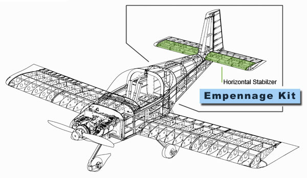
Basically, the empennage kit includes everything aft of the canopy and is about half of the total fuselage.

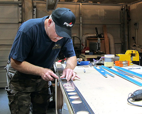
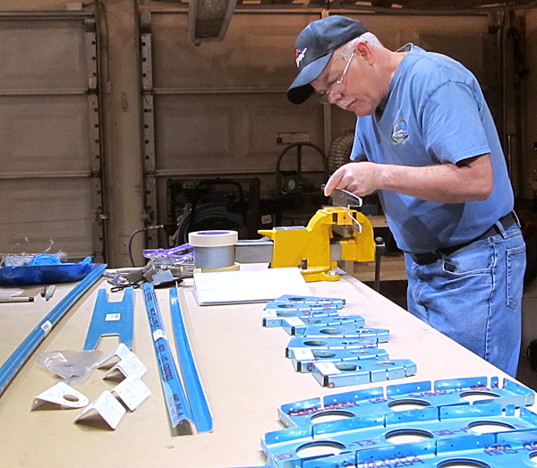
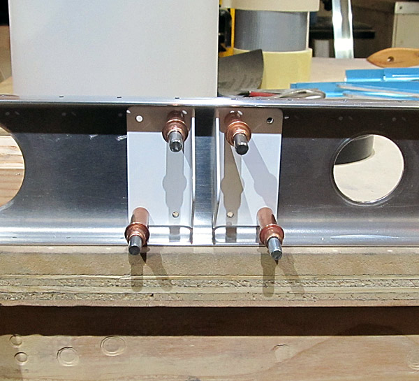
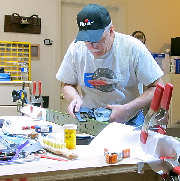
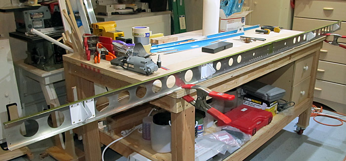
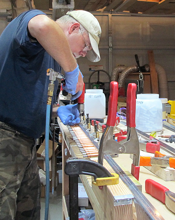
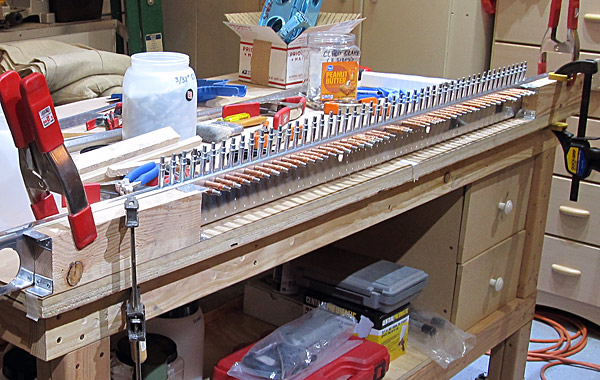
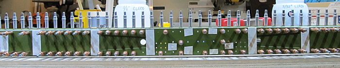
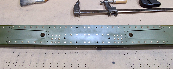
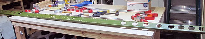
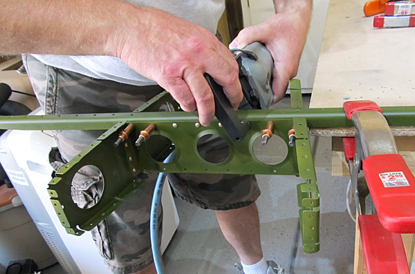
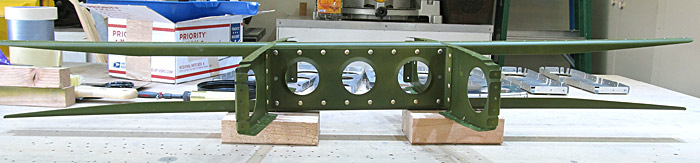
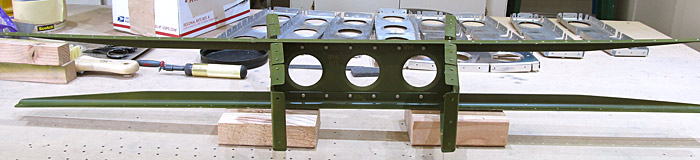
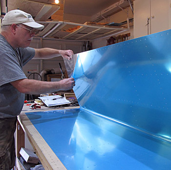
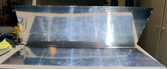
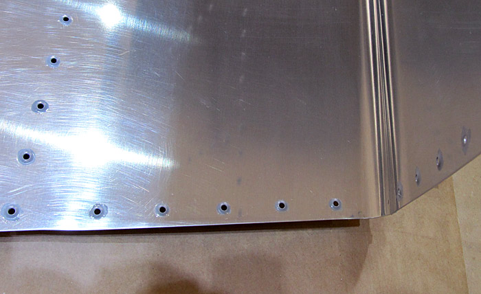
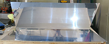
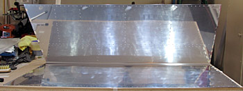
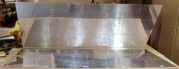
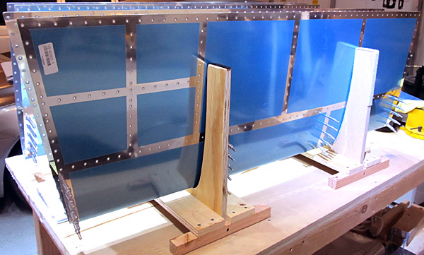
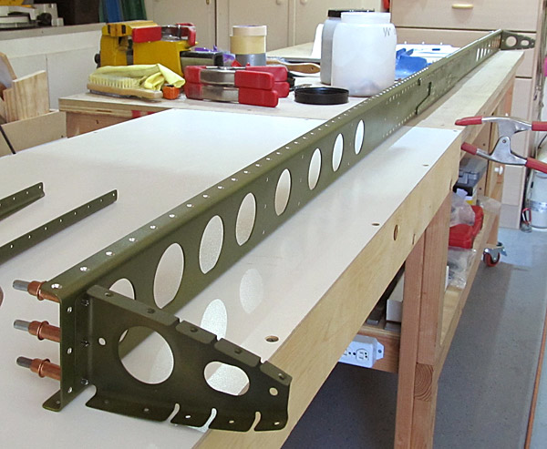
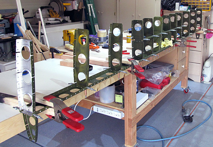
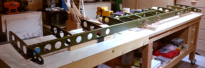
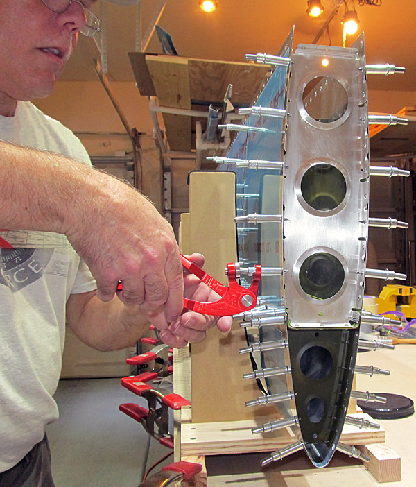
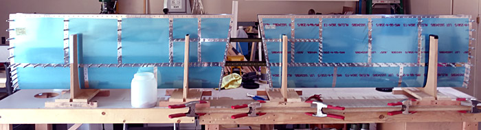
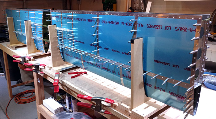
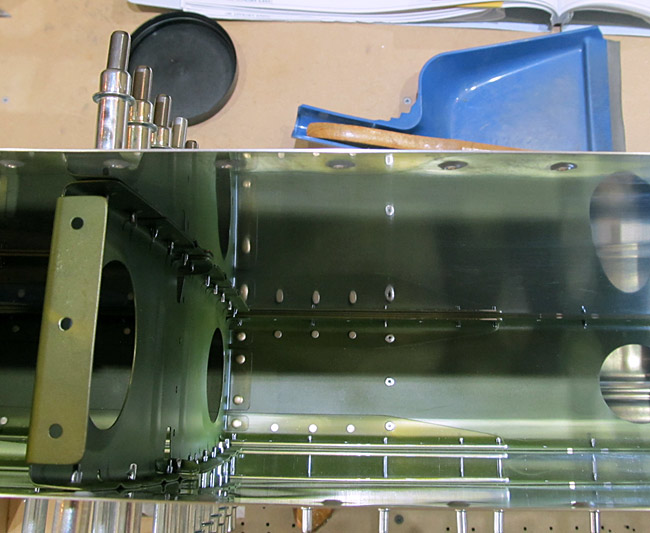
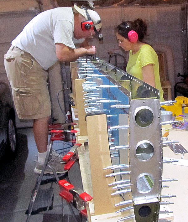
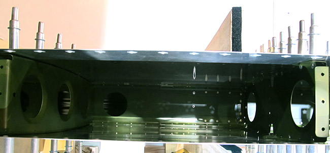
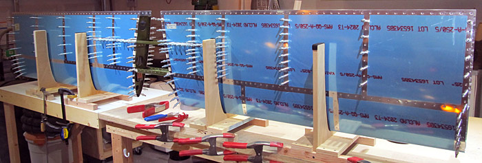
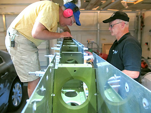
The third item to work on according to the builder's plans is the Horizontal Stabilizer.
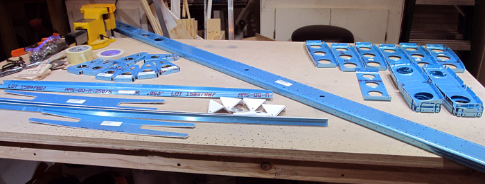
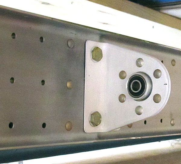
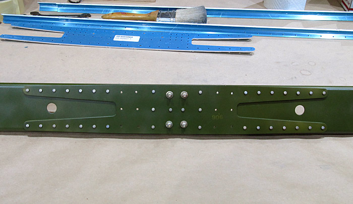
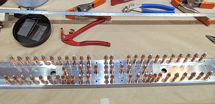
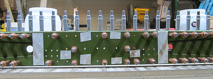
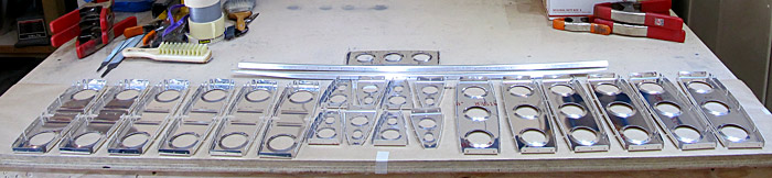
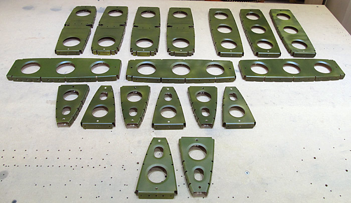
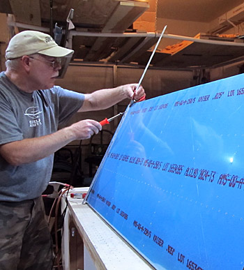
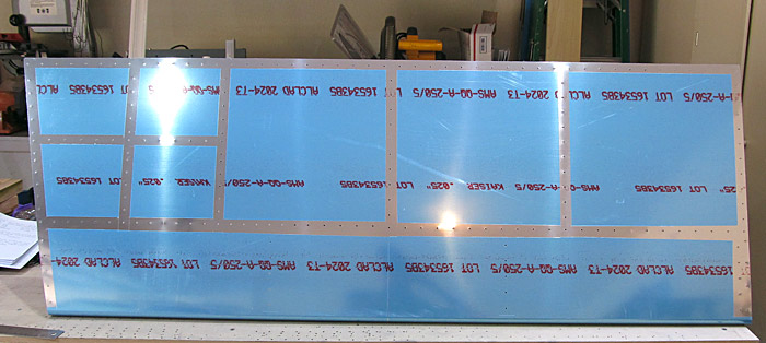
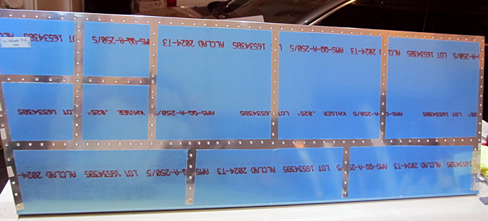
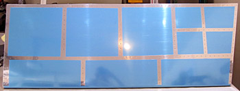
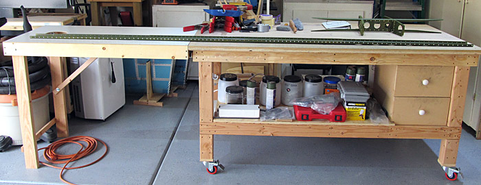
I pulled the individual parts from the inventory that are needed to assemble the horizontal stabilizer section.

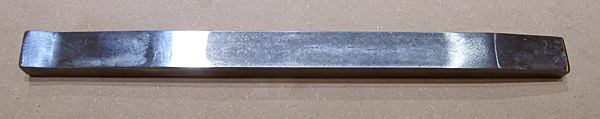
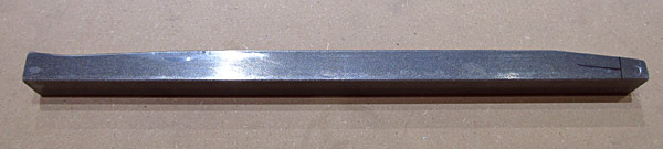
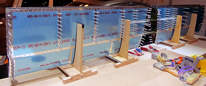
The parts included: HS-00903-1, HS-912, HS-906, VA-146, HS-911, HS-00913, HS-00914, HS-00902-1, HS-00907-1, HS-905, HS-1004, HS-904, HS-00901-1, and HS-00916.

Horizontal Stabilizer Parts

These are all of the parts except for the two skins that are needed.


Deburring Horizontal Stabilizer parts

As always, the process begins with the task to deburr any rough or machined edges before clecoing (using small clamps to temporarily hold pieces together) and match-drilling pre-punched holes for the final riveting process.

We are using a combination of flat and round files, scotch-brite (gray- "ultrafine" pads), and sandpaper to polish the edges and lightening holes before proceeding to the next step.

The plans start out with the construction of the rear horizontal stabilizer spar (HS-903-1) first.

I know, Van's airplane build, Piper hat, (we used to own a Piper Cherokee).....

Deburring HS Rear Doubler

The rear horizontal spar doubler (HS-906) is next.

Raw HS Rear Doubler

As you can see the machined edges of the parts can be fairly rough.

Deburred HS Rear Doubler

Here is the same part completely deburred around the edges.


Final Drilling Rear Spar Doubler Holes

The rear spar doubler (HS-906) is then clecoed in place onto the rear spar (HS-00903-1) and all holes common to both the doubler and rear spar are final drilled/reamed to size #30 (1/8") using the pneumatic drill.

*Van's does such a great job of pre-punching the holes that usually a #30 reamer works just fine.

Four Holes For Center Hinge

There are four holes in the center of the rear horizontal stabilizer spar (HS-00903-1) and doubler (HS-00906) that aren't pre-punched so they needed to be match drilled to #30 (1/8") size. (They are covered with the two inner pieces of tape and will eventually have a rib attached.)

The two center holes are machine countersunk to receive AN426AD4-6 rivets and, in addition, the top two and bottom two holes were final drilled to #12 (3/16") to receive AN3-5A bolts and hardware to attach the center hinge bracket assembly.

Rear Spar Hinges

There are eight hinge brackets (HS-912) that were clecoed and final drilled/reamed to #30 (1/8") size and were numbered in sequence (1-8 left to right) so that they could be placed in the same position during the riveting process.

Each bracket center hole (on the tab) was final drilled to #12 (3/16") size.

Everything was then diassembled and primed with Tempo A702 green zinc phosphate primer.


Riveting The Rear Spar

The horizontal stabilizer rear spar doubler (HS-00906) was attached to the rear horizontal stabilizer spar (HS-00903-1) and riveted together using AN470AD4-6 rivets and two center AN426AD4-6 rivets.

There are 12 holes that do not receive rivets at this time and they were taped over (see photo above) so that I didn't accidentally rivet them today.

I set all of these rivets with our pneumatic squeezer.

Riveted The Hinge Brackets To The Rear Spar

The eight rear horizontal stabilizer hinge brackets (HS-912) were riveted onto the rear horizontal stabilizer (HS-00903-1) with AN470AD4-5 rivets using the pneumatic squeezer.

* You might be wondering why one side of the spar is painted with primer and the other side isn't? That is because later when I paint the airplane (I'm planning on using Stewart Systems Waterborne Paint) I won't have to sand the existing primer in order to re-paint with their primer.


Riveted The Inboard Hinge Assembly

The flange bearing (VA-146) was riveted between the two inboard hinge brackets (HS-911) using AN470AD4-6 rivets being careful to keep everything square to each other by clamping the entire assembly to the flat benchtop. I used our pneumatic squeezer to set the rivets.

Bolted The Inboard Hinge Bracket To The Rear Spar

The inboard hinge assembly was bolted to the rear horizontal stabilizer spar (HS-00903-1) using the called out hardware (AN3-5A, NAS 1149F0363P, and MS21042-3).

Final Torque value was 42 inch/pounds.


Trim The Front Horizontal Spar Cap

Van's instructs you to draw layout lines to trim the front horizontal stabilizer spar caps (HS-00913) so that they fit inside of the front spar (HS-00902-1). There are two of them and I cut them out using our bandsaw.

Just like everything else, all of the edges have to be filed and deburred.

Trim The Front Horizontal Spar Stringer

Since I had the bandsaw out, I drew the layout lines for the front horizontal stabilizer spar stringers (HS-00914) and trimmed the excess material from them as well.

Debur The Front Horizontal Spar

Déjà vu!

Deburring the front horizontal stabilizer spar (HS-00902-1).

Debur The Front Horizontal Spar Doubler

Deburring and filing the front horizontal stabilizer spar doubler (HS-00907-1).


Match Drilling Front Horizontal Spar Caps

After all of the front horizontal stabilizer spar components had their edges deburred it was time to start working on the spar caps (HS-00913).

The plans instruct you to draw a mark onto the spar cap (HS-00913) a distance of 3/16" from the end and then center that mark over the 28th hole of the front horizontal stabilizer spar (HS-00902-1) flange. Then from the other end of the spar you are supposed to check to make sure that the spar cap covers the 28th hole of the front spar......so far so good

Match Drilling Front Horizontal Spar Caps

None of the holes are pre-punched so everything has to be match drilled using the existing holes in the front horizontal stabilizer spar (HS-00902-1) as guides.

The top spar cap was clamped into place and all of the #30 (1/8") holes from the front spar were match drilled into the spar cap.


Match Drilling Front Horizontal Spar Caps

Let the match drilling begin!

Match Drilling Front Horizontal Spar Caps

After the #30 holes were match drilled, everything was disassembled, deburred and clecoed and clamped together to match drill the flange #40 (3/32") holes into the spar cap.

Match Drilling Front Horizontal Spar Caps

Here is what it looks like after all of the holes have been match drilled and clecoed.

Of course all of this has to be done twice because there are two front horizontal stabilizer spar caps (HS-00913)!

Final Drilling Front Horizontal Spar Doubler

The front horizontal stabilizer spar doubler (HS-00907-1) was clecoed to the front horizontal stabilizer spar (HS-00902-1) and all #30 (1/8") holes common to both were final drilled.

*There are six holes that are not to be drilled at this time so make sure that they are covered with tape.

Final Drilling Front Horizontal Spar Doubler

The upper and lower front horizontal stabilizer spar caps (HS-00913) were then clecoed onto the assembly and four holes common to the caps, doubler, and spar were final drilled to #12 (3/16") size.

*These will receive AN3-6A bolts later in the build.

There are two holes near the center of the front horizontal stabilizer doubler (HS-00907-1) that were final drilled on the drill press to 1/4" that will later receive AN4-7A bolts in the build.

There are several other holes in the doubler and spar that need to be machine countersunk for AN426AD4 and AN426AD3 type rivets which are to be done at this time also.


Riveting Front Horizontal Spar Together

After all of the parts for the horizontal stabilizer front spar were scuffed, cleaned, and primed with Tempo A702 green zinc phosphate primer they were clecoed together for final riveting.

There are several holes that do not receive rivets at this time so they were covered with masking tape to avoid any accidental riveting.

Riveting Front Horizontal Spar Together

The taped over holes will receive ribs later on in the construction of the horizontal stabilizer.

Riveting Front Horizontal Spar Together

We used our pneumatic squeezer to set all of the rivets here. There are several different sizes needed so you have to be careful and follow the plans.

AN426AD4-6, AN426AD4-7,AN470AD4-5, AN470AD4-6, and AN470AD4-7 rivets were used along the face (or web) of the spar assembly and AN426AD3-4.5 rivets were used along the nine top and nine bottom holes located on the center flanges of the horizontal stabilizer spar and spar caps.

Riveting Front Horizontal Spar Together

Peeling Vinyl From Horizontal Stabilizer Ribs

Now that the front and rear horizontal stabilizer spars have been assembled it is time to move on to the ribs.

There are 20 individual ribs and one stringer web that need to be unwrapped from the blue protective vinyl that Van's uses to wrap them in.

I usually use a sharpie pen to label the parts numbers to keep everything organized as well.

There are six inner ribs HS-1004, they have two lightening holes on them and six additional inner ribs HS-904, which have three lightening holes. There are eight nose ribs HS-905 and one stringer web HS-00916, and two stringers HS-00914 that all need to be deburred.

Horizontal Stabilizer Ribs
Deburring Horizontal Stabilizer Ribs

Here we go again!

I find that the flat and round files work the best for me in the deburring process.

I usually follow up with very light sanding with 600 grit sandpaper and gray- "ultrafine" scotch-brite pads to prepare them for zinc phosphate priming.


Horizontal Stabilizer Nose Rib Modification

As per the plans, two nose ribs (HS-905) of the horizontal stabilizer need to be modified by opening the rib flanges from 90° an additional 10°.
*I used seaming pliers to make the addtional bend.

The ribs also need to be fluted so that the rivet holes are aligned.

Horizontal Stabilizer Inspar Rib Modification

Next, two inboard inspar ribs (HS-1004) need to be modified.

The foward flange needs to have an additional 12.5° bend inward and the rib web needs to be bent upwards an additional 2.5° (starting between the first notch of the rib flange).

Horizontal Stabilizer Inspar Rib Modification

The aft end of the inboard inspar rib (HS-1004) flange needs to be modified by opening it up an additional 10°.

These pairs of modified ribs need additional #30 holes match drilled into the flanges where they attach to the horizontal stabilizer front spar.

The two modified nose ribs (HS-905) were clecoed in place to the front spar and two additional holes were match drilled into the aft flange.

The two modified inboard inspar ribs were clecoed into place and an additional #30 hole was match drilled to the center of the forward flange.


Horizontal Stabilizer Cradles

Four cradles were made for the next stages of the build.


Horizontal Stabilizer Web Assembly

The deburring process takes some time because of all of the small tabs and gaps in the ribs.

I wanted to focus on the parts that make up the web/stringer assembly first so that they could get assembled and painted as I worked on the tedious deburring process.

I marked the top holes in the modifed inspar ribs and nose ribs that don't get dimpled, and then dimpled the remaining #40 holes using a 3/32" sub-structure dimple die set in a hand held squeezer.

*The undimpled holes are where a fairing will be attached later in construction. (The ribs were fluted as well.)

I clecoed the stringer web (HS-00916), to the modified inspar ribs (HS-1004), and then clecoed the stringers (HS-00914) to the stringer web (HS-00916).

Horizontal Stabilizer Web Assembly

Everything was labled so they could be reassembled in the same order and then disassembled.

I machine countersunk all of the #40 holes in the stringers (HS-00914) to receive .025 inch skin dimples.

The parts were all washed with acetone and primed with Tempo A702 green zinc phosphate primer.


Horizontal Stabilizer Web Assembly

After the primer had dried for a couple of days, yeah, meanwhile I was deburring ribs..... I clecoed the web stringer (HS-00916), to the modified inboard inspar ribs (HS-1004), and riveted them together using AN470AD4-4 rivets and the pneumatic squeezer.

The stringers (HS-00914), were next, and I was able to get all of the AN470AD4-4 rivets set with the pneumatic squeezer except the four corner rivets had to be set using our 3X rivet gun with a eight inch, 1/8" domed extension set installed and a bucking bar because of the tight spaces.

Horizontal Stabilizer Web Assembly

Horizontal Stabilizer Ribs Primed

All of the rest of the ribs have had the flange angles checked, been fluted, and dimpled to receive AN426AD3 type skin dimples, and primed with Tempo A702 green zinc phosphate primer.

*Make sure that all of the small tabs in the inboard inspar ribs don't get dimpled!


Horizontal Stabilizer Front Spar Countersinking Horizontal Stabilizer Front Spar Countersinking

The Horizontal Stabilizer front spar assembly (HS-00902-1) was clamped to the bench and all of the #40 holes in the top and bottom flanges were reamed and machine countersunk to receive .025" skin dimples.


Horizontal Stabilizer Rear Spar Countersinking Horizontal Stabilizer Rear Spar Countersinking

The Horizontal Stabilizer rear spar assembly (HS-00903-1) was clamped to the bench and all of the #40 holes in the top and bottom flanges were reamed and machine countersunk to receive .025" skin dimples.


Horizontal Stabilizer Skin Devinyl Horizontal Stabilizer Skin Devinyl
Horizontal Stabilizer Skin Devinyl

Next, the Horizontal Stabilizer Skins (HS-00901-1) need to have the blue protective vinyl stripped so that the work can proceed so I pulled all of the inner vinyl off and used a soldering iron to remove just enough vinyl to work around the rivet holes and also to protect the outer skin as much as possible.

The edges of the skins and the #40 holes were final reamed and deburred.

When I got to the second skin I noticed that somehow a scratch about 1/4" long and shaped like a "p" was on the inside of the skin. I "dressed out" the scratch with 600 and finished with 1000 grit sandpaper and then measured the depth with our micrometer and found that it was .0015" deep after sanding. It was 11/16" below the center of the fourth #40 rivet hole out from the root. These rivets correspond to where the stringer (HS-00914) will be attached.

I think that technically this might be okay, but for safety sake, I ordered a new skin HS-00901-1.

Horizontal Stabilizer Skin Flaw

At this point the horizontal stabilizer skins (HS-00901-1) are exactly alike but now they need to be marked so that there is a left skin and a right skin.

I put pieces of tape at the outer tip of the skin and tape at the inner angled root side of the skin. This will now be the left horizontal stabilizer skin. (There are eight holes at the tip and five holes at the root.) When I receive the new skin from Van's I will have to mark it opposite to this one so that it will become the right horizontal stabilizer skin.

It is important that these holes do not get dimpled because there will be a fairing attached at these points later on in the build.

Horizontal Stabilizer Left Skin

Horizontal Stabilizer Left Skin Dimpling

It's time to start dimpling!

I dimpled the left horizontal stabilizer skin (HS-00901-L) using the DRDT-2 dimpling machine being careful not to dimple the eight holes on the outboard tip and the five holes on the inboard root where they were marked with tape.


It is really tight in the middle of the skin where the nose ribs (HS-905) attach and I couldn't reach the very first hole behind the leading edge with the dimple machine so I had to use the Avery Pop Rivet 3/32" Dimple Tool to dimple that hole of the skin.

Avery Pop Rivet Dimple Kit

It is simple to use, all you have to do is place a nail provided through the male dimple die on the outside of the skin and then place the female dimple die on the inside of the skin and then use a pop rivet gun to gently squeeze the dimple into shape.

Avery Pop Rivet Dimple Use

It turned out pretty nice!

Horizontal Stabilizer Left Skin Dimpling

Horizontal Stabilizer Left Skin Dimpling

The left horizontal stabilizer skin (HS-00901-L) is now dimpled!


For something different, I decided to prime the individual dimpled holes with PTI Self Etching Gray Zinc Phosphate Primer. Hopefully this might cut down a little weight by just painting small spots. I am only doing this on the inside of the skins over the dimples.

Horizontal Stabilizer Left Skin Primed

Horizontal Stabilizer Right Skin Horizontal Stabilizer Right Skin

The right horizontal stabilizer skin (HS-00901-R) is the mirror of the left skin but care needs to be taken that the angled (or root) side of the skin should be on the left side and the squared tip should be on the right. (As viewed from the aft looking forward towards the leading edge.)


Horizontal Stabilizer Noseribs Clecoed To Skin

There are four nose ribs (HS-905) that need to be clecoed into place on the inside of the left and right horizontal stabilizer skins (HS-00901-L and R) in preparation for riveting.

We placed them into the pre-made cradles to support them while we worked on them.

The plans called for (AN426AD3-3.5) rivets here.

Horizontal Stabilizer Noseribs Riveted To Skin

The space is very limited in this area so it really helped to have two of us when setting the rivets.

My wife used our 3x rivet gun with a swiveling mushroom set on the outside and I used two different bucking bars to reach the rivets on the inside.

I used a 1" x 1" x 2 ¼" tungsten bucking bar for most of the rivets but had to use the specialty RV14 empennage bucking bar that Cleaveland Aircraft tool sells (item: BBRV10) to set the hard to reach two rivets at the nose of the rib.

Cleaveland RV14 Empennage Bucking Bar

This is the RV14 empennage bucking bar tool that Cleaveland Aircraft tool sells (item: BBRV10).

It is 14" x 1" x ¾" long and weighs 2.8 pounds.

Cleaveland RV14 Empennage Bucking Bar

It really helped extend my reach and get into the really tight space plus the plans call for a tool like this later on in construction.

*See figure 4: Special Bucking Bar, page 09-17.

Horizontal Stabilizer Noseribs Riveted To Skin

This is what the ribs look like on the inside of the skin after the rivets have been set.

Horizontal Stabilizer Noseribs Clecoed To Skin

This is what the ribs look like on the outside of the skin after the rivets have been set.


Workbench Table Extension

The Horizontal Stabilizer is about 10 feet long so I needed to build an extension for my 6 foot workbench. I had a 4 foot by 2 foot cornhole/bean bag toss platform that I built some time ago so.....voilà now I have a 4 foot extension on my work table. It is removable and will fold up in case I need to use it again sometime!


Horizontal Stabilizer Noseribs Clecoed To Spar

Two nose ribs (HS-905) were clecoed onto the ends of the horizontal stabilizer front spar assembly (HS-00902-1) and riveted with AN470AD4-4 rivets. I set them with our pneumatic squeezer.

*Be careful here and make sure that you use the inner set of holes on the spar and not the outer set!

Horizontal Stabilizer Noseribs Riveted To Spar

Squeezing the rivets with the pneumatic squeezer.


Horizontal Stabilizer Orientation Reference

*From this point on it is important to make sure that all of the pieces of the horizontal stabilizer assembly are oriented properly.

The plans mention the two groups of nine holes three separate times to aid in the orientation process. (They indicate the bottom of the spar/horizontal stabilizer.)

One extra check is to verify that the non-dimpled holes, located at the top of the skins, are located opposite the two group of nine holes. These will be used later to attach the root fairing.

Horizontal Stabilizer Inspar Ribs To Spar

Keeping orientation in mind, the inspar ribs (HS-904) and (HS-1004) were clecoed onto the horizontal stabilizer front spar assembly.

Horizontal Stabilizer Inspar Ribs Riveting to Front Spar

I found that in order to use our pneumatic squeezer to set the three AN470AD4-4 rivets on each of the six (HS-904) inspar ribs, and four (two-AN470AD4-4 located in the center, two- AN470AD4-5 located at the outer tabs) rivets on each of the six (HS-1004) inspar ribs, it would be best to clamp the front spar assembly face down to supports extenting from the workbench.

I placed the manufactured heads on the inside of the spar and the tails are on the face side of the spar. This really worked well and the weight of the pneumatic squeezer helped keep the flanges of the inspar ribs flush against the spar while riveting.

*The center two inspar ribs (HS-1004) were not riveted at this time because they will be sharing rivets with two special (modified) nose ribs (HS-905) later in construction.

Horizontal Stabilizer Inspar Ribs Riveted To Front Spar

Horizontal Stabilizer Skins Clecoed To Spar

I set up the four pre-made cradles onto the workbench to support the horizontal stabilizer skins (HS-00901-L and R) making sure to keep the orientation of the skins correct (angled, non dimpled sides in the center opposite the two groups of nine holes as per plans).

The horizontal stabilizer front spar/inspar assembly was then inserted into position between the skins and then clecoed together.

The two special modified nose ribs (HS-905) were clecoed into place in the center section at this time as well.

Horizontal Stabilizer Skins In Cradles
Horizontal Stabilizer Noseribs Riveted To Spar Assembly

The next step called for in the plans is to rivet the entire spar assembly to the four nose ribs (HS-905) previously installed to the skins with LP4-3 rivets. (There are three per rib.)

As you can see in the photograph, the space is tight here and I found that if I used my "PowerFast" Professional Swivel Head Rivet Tool, which has handles that point in a vertical (more or less) direction, the task was fairly easy.

Horizontal Stabilizer Noseribs Riveted To Spar Assembly

*I bought this tool years ago when I built my first airplane and I don't think they are available anymore but the point is to find a hand rivet tool that has grips that are vertically aligned, or nearly so, with the head and it will make the job go much easier.


Horizontal Stabilizer skins Riveted To Front Spar Assembly

Now it's time to start riveting the horizontal stabilizer skins (HS-00901- Left and Right) to the flanges of the front spar assembly.

My wife used our 3x rivet gun with a flat swivel mushroom set on the outside of the skin while I used a 1" x 1" x 2 ¼" tungsten bucking bar to reach the inside tails of the rivets. (Tight spaces here!)

There are several different rivet sizes called out by the plans on page (8-13) so you have to pay attention as to what rivet to use. (For today's session basically there were three rivet sizes used: AN426AD3-4, AN426AD3-4.5, and AN426AD4-5.)

We started in the middle of each skin section and worked outwards towards the tip and center and set all of the rivets along the center spar on both the top and bottom sides of the stabilizer.

Horizontal Stabilizer skins Riveted To Front Spar Assembly

Inside look at one of the bays.

Horizontal Stabilizer skins Riveted To Front Spar Assembly

Horizontal Stabilizer Ribs Riveted To Skin

A good friend and fellow RV builder volunteered to help me rivet some ribs of the horizontal stabilizer to the skin.

He used the 3x rivet gun with a flat swivel mushroom set on the outside of the skin while I used a 1" x 1" x 2 ¼" tungsten bucking bar to reach the inside tails of the rivets.

Van's suggests that you start at the midway point of one section of the horizontal stabilizer and rivet vertically up each rib to the stringer line using AN426AD3-3.5 rivets and then go horizontally across the stringer with AN426AD3-4 rivets and then finish the remainder of the ribs vertically with AN426AD3-3.5 rivets.

Time was limited but we did manage to get up to the stringer line on both sides of the right half of the horizontal stabilizer....cool!


Horizontal Stabilizer Ribs Riveted To Skin

My wife and I riveted the rest of the (HS-00901-1) horizontal stabilizer skins to the flanges of all of the (HS-904) and (HS-1004) inspar ribs as well as to the (HS-00914) stringers according to the directions called for in the builder's manual.

We used the same tools and assembly methods as before and set the AN426AD3-3.5 and AN426AD3-4 rivets up to where the (HS-00903-1) rear horizontal stabilizer spar assembly will be placed.

Horizontal Stabilizer Rear Spar Assembly In Place

Next, the (HS-00903-1) rear horizontal stabilizer spar assembly was clecoed in place.

Horizontal Stabilizer Rear Spar Notch

*It is important to keep orientation in mind at this point and Van's makes a special note in the plans to tell you to keep the rear horizontal spar assembly "spar notch" in line with the groups of nine rivets (on the front spar) oriented towards the bottom of the horizontal stabilizer.

This is what the spar notch on the rear spar looks like.

Horizontal Stabilizer Rear Spar Attach To Ribs

The (HS-00903-1) rear horizontal stabilizer spar assembly gets attached to the (HS-904) and (HS-1004) inspar ribs with LP4-3 blind rivets.

We set those using our CherryMax G-27 hand rivet gun.
(There are three per rib.)


Horizontal Stabilizer Rear Spar Attach To Skin

We attached the horizontal stabilizer skins (HS-00901-1) to the rear horizontal stabilizer spar (HS-00903-1) with AN426AD3-4 rivets set with our pneumatic squeezer.

We started at the center and worked our way towards the tips alternating from the top side to the back side of the stabilizer.

The light is a new gizmo...really lights things up huh?

Horizontal Stabilizer Rear Spar Attach To Ribs

At this point, after setting all of the AN426AD3-4 rivets, we wanted to take the horizontal stabilizer out of the cradles and lay it on it's side so that we could use our 3x rivet gun to set the remaining rivets which are AN470AD4 type rivets and we didn't want to put any stress on the leading edge of the stabilizer while setting them.

The end inspar ribs (HS-904) were attached to the rear horizontal stabilizer spar assembly (HS-00903-1) with AN470AD4-4 rivets set with our 3x rivet gun and a 1" x 1" x 2 ¼" tungsten bucking bar.

The center horizontal stabilizer inspar ribs (HS-1004) were attached to the rear horizontal stabilizer spar assembly (HS-00903-1) with AN470AD4-6.5 rivets.


Horizontal Stabilizer Rear Spar Attach To Ribs

The next step of attaching the two modified horizontal stabilizer nose ribs (HS-905) and the two modified horizontal stabilizer inspar ribs (HS-1004) to the front horizontal stabilizer spar assembly (HS-00902-1) was the most challenging of the build process so far.

The angles and tight spaces makes it an extremely difficult place to work in.

After a few failed rivet sets and subsequent drill outs I wondered if there was a better way to do this??

After consulting Van's about the situation, the engineers said that CherryMax structural rivets could be substituted for the AN470AD4-7 and AN470AD4-8 rivets called for in the builder's plans.

You have to buy a CherryMax grip gauge (GS-269C3,) figure out what size CherryMax rivet to use, and order the special rivets.

*Go to the CherryMax website and they tell you how to do everything including how to figure out what size rivet to use.

Horizontal Stabilizer Rear Spar Attach To Ribs

This is the CherryMax grip gauge (GS-269C3).

Horizontal Stabilizer Rear Spar Attach To Ribs

These are the CherryMax rivets that were set on the right horizontal stabilizer modified nose rib (HS-905) to right horizontal modified inspar rib (HS-1004) to front horizontal spar assembly (HS-00902-1).

Yes, I was able to set one AN470AD4-7 rivet!

Horizontal Stabilizer Rear Spar Attach To Ribs

The center section is done!

Horizontal Stabilizer Rear Spar Attach To Ribs

The horizontal stabilizer is done!


So on to the elevators.......▶
◀.......Click here to go back to the rudder

Amazon Affiliates Disclosure

Aerotoons®, is a participant in the Amazon Affiliates Program. For more information please visit our terms of use and policies page.